newsdeskdan said:
Motocar said:
Motocar said:
Next cutaway drawing BV P.210

Ready speculative cutaway drawing Blohm & Voss P-210, link

http://www.secretprojects.co.uk/forum/index.php/topic,23005.msg310600.html#msg310600

Saludos newsdeskdan...!

Certainly the work of Peter Allen differs, only accompanies the speculative cutaway, is very vague information of that project although some models have flown testing the validity of the design. Just a small and modest contribution to the thousands of projects that were left in the inkwells ...! Motocar
Lovely, but this is the only known contemporary drawing of the Blohm & Voss P 210, from German Aircraft: New and Projected Types. Flitzer's art... differs from it somewhat.
 
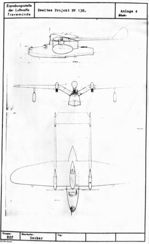
Second project BV 138 with little engine nacelle turret.
Hi Dan, do you have the source from this very early Ha 138 Drawing? This report was entitled "Chronik des See-Fern Aufklärers von 1933 bis zum heutigen Tage" (Chronicle of the long range maritime reconnaissance seaplane types from 1933). I am really interested in this chronicle report, which could have been published by the Travemünde test center.
Kind regards,
starmountain
 

Attachments

  • Zweites Projekt BV 138.jpg
    Zweites Projekt BV 138.jpg
    397.7 KB · Views: 697
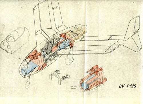
Do we know if the BV P.215 ever achieved wind tunnel testing and/or a mockup being built?
 
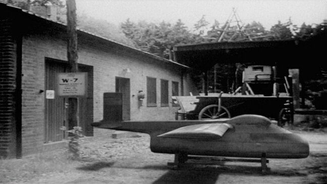
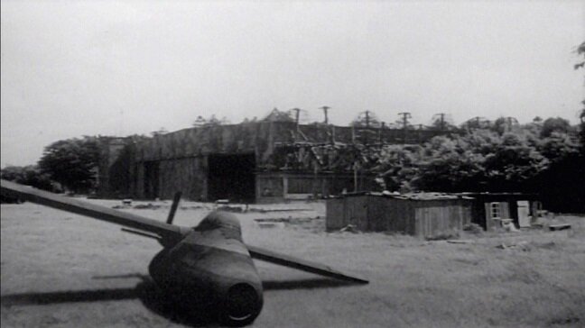
The 2nd one shows a very obvious seam between the shadow and wingtip.

Besides that its a very large model. Were they even running the big tunnels at the end of the war? The power usage of such tunnels is immense and its hard to see them using the bigger tunnels unless they could avoid it.
 
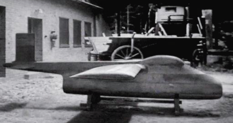
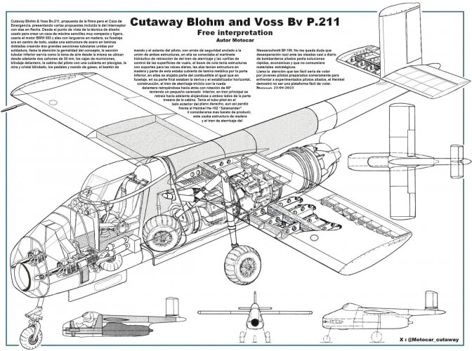
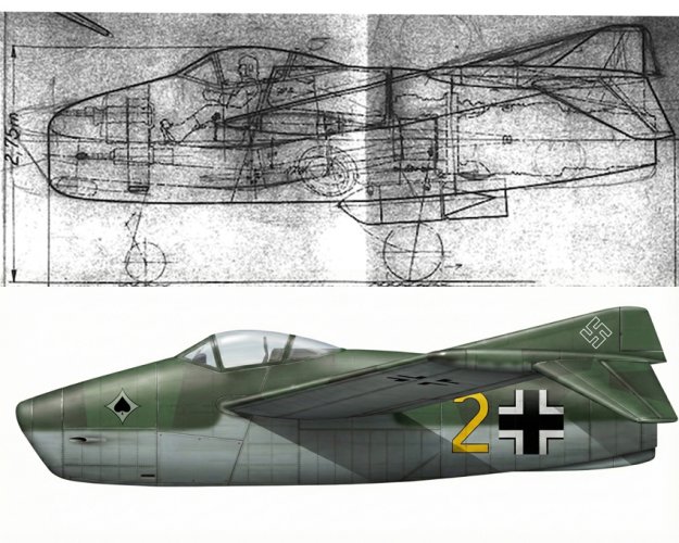
Very interesting and never seen photo: Blohm & Voss P 211 wind tunnel model from FliegerRevue X 90

As the text tells us,it was not fake;

Bottom left: The wind tunnel model
of the hunter Blohm &
Voss P 211, a competing project
to He 162, is behind
End of the war unnoticed
the company's premises.
 
The 2nd one shows a very obvious seam between the shadow and wingtip.

Besides that its a very large model. Were they even running the big tunnels at the end of the war? The power usage of such tunnels is immense and its hard to see them using the bigger tunnels unless they could avoid it.

As the text tells us,it was not fake;

Bottom left: The wind tunnel model
of the hunter Blohm &
Voss P 211, a competing project
to He 162, is behind
End of the war unnoticed
the company's premises.

It seems unlikely to be genuine. On October 12, 1944, Richard Vogt wrote a brief history of his involvement in the Volksjaeger project. He was feeling embittered because his design lost and he wanted to make sure posterity knew - when the He 162 failed - that he had been right all along.
He recounts the various twists and turns - his original design, drafted between September 10, 1944, and September 14, 1944, was the swept-wing P 211.01-01. Having seen Heinkel's simpler and less risky P 1073 at the comparison meeting on Semptember 14, his engineers revised the P 211 to create the straight-wing P 211.01-02 (the design apparently shown in the FliegerRevue X 90 photos). This was described in a new report dated September 29, 1944.
So the new design was created - on paper - in two weeks.
But Hitler had already been persuaded to approve the P 1073 on September 23, 1944. And Knemeyer formally announced this decision on September 29 - the same day that the P 211.01-02 design was published.
Vogt was annoyed because he felt that the P 211.01-02 was now superior to the P 1073 (he was probably right) but his design had been rejected primarily on the basis of concerns about the length of the intake duct. So first, on October 2, 1944, Vogt appealed the decision and his appeal was rejected.
Then he invited the very well respected Dietrich Kuechemann from the AVA to Hamburg to assess his design, particularly with regard to the intake duct - and Kuechemann reported the following day (October 5) that the P 211.01-02 was superior to the P 1073 in most respects. The B&V duct was relatively short and unlikely to result in reduced airflow to the engine, he wrote, and with the P 1073 there were unresolved concerns about the effect of the boundary layer on the intake positioned above the fuselage.
And here's the interesting bit:
Kuechemann arranged for 'rough' wind tunnel tests to assess the effect of air flow on ducts of different lengths and from different angles and whether vibrations occurred under different conditions. The tests found that airflow was unaffected up to angles of 60-degrees.
The models used in these tests appear to have been different lengths of cylindrical piping with either a 'sharp' or 'rounded' edge. Kuechemann's text (undated, but definitely received by Vogt on or before October 12 - see below) says: "Die Abrundung des Rohreinlaufes bringt, gegenueber dem scharfkantigen Rohr, nur ein frueheres Einsetzen der Schwingung bei etwas kleineren Schraeganblasungswinkeln."

I wrote in Secret Projects of the Luftwaffe: Heinkel He 162 and also in Secret Projects of the Luftwaffe: Jet Fighters 1939-1945 that the AVA had conducted wind tunnel tests which proved that Vogt's intake duct was fine. And they did. But they didn't go to the time, trouble and expense of constructing a full scale P 211.01-02 model! They just used bits of pipe.
However, if all you knew was the that the AVA carried out wind tunnel tests to prove that the P 211.01-02's duct was fine, you might think that such a model had been built for that purpose. But it wasn't. Vogt sent the results of the AVA tests to the Chef-TLR on October 14 but clearly by this point the He 162 was unstoppable.
The bill for B&V's involvement in Volksjaeger appears to have been RM 1100 and the invoice for this sum seems to bounce around between various different institutions well into January 1945 and it's not clear if B&V ever got paid for it.
The P 211.01-02 only really existed for a couple of weeks before it was well and truly rejected. Building a large wind tunnel model of it would have been utterly pointless.

 
Last edited:
Very interesting and never seen photo: Blohm & Voss P 211 wind tunnel model from FliegerRevue X 90

As the text tells us,it was not fake;

Bottom left: The wind tunnel model
of the hunter Blohm &
Voss P 211, a competing project
to He 162, is behind
End of the war unnoticed
the company's premises.
Just for comparison ...
 

Attachments

  • 3301.jpg
    3301.jpg
    90.7 KB · Views: 425
  • 3303.jpg
    3303.jpg
    85.9 KB · Views: 485
That natter looks fake too. Again the shadows look off and the wing break is really odd.
 
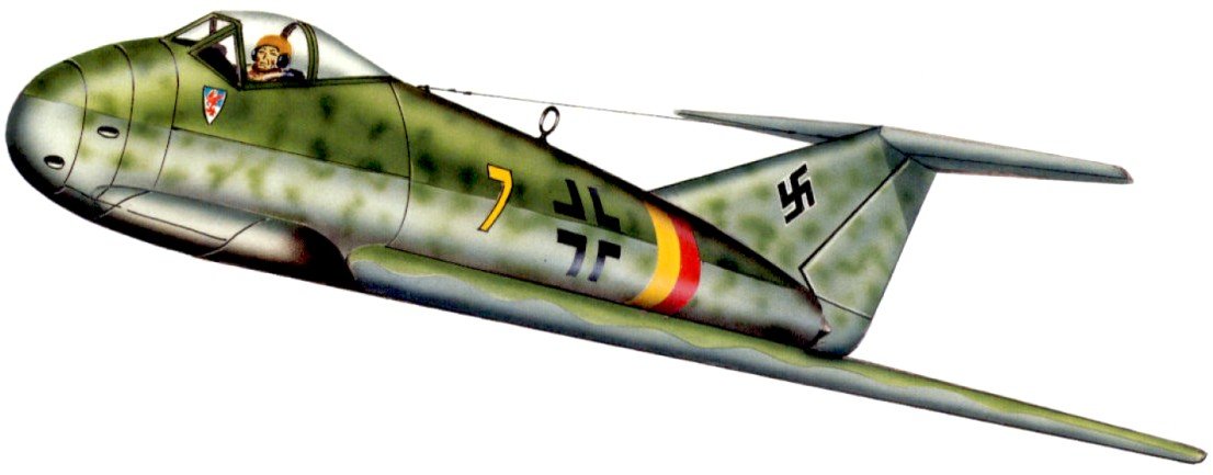
The newest November issue of the German magazine "Flugzeug Classic 11/21" features an article about the proposed Blohm & Voss BV P 211.02 "Volksjäger" as part of the Emergency Fighter Program design competition. Again, the graphics for this article is contributed by the aviation artist Anastasios Polychronis.
Technik - Typengeschichte
Blohm & Voss BV P 211.02: Der wirkliche „Volksjäger“?
Der noch bei Kriegsende hergestellte „Volksjäger“ Heinkel He 162 ist bis heute bekannt. Es gab aber auch weniger berühmte Alternativen wie die P 211.02. Wäre sie die bessere Option gewesen?
 
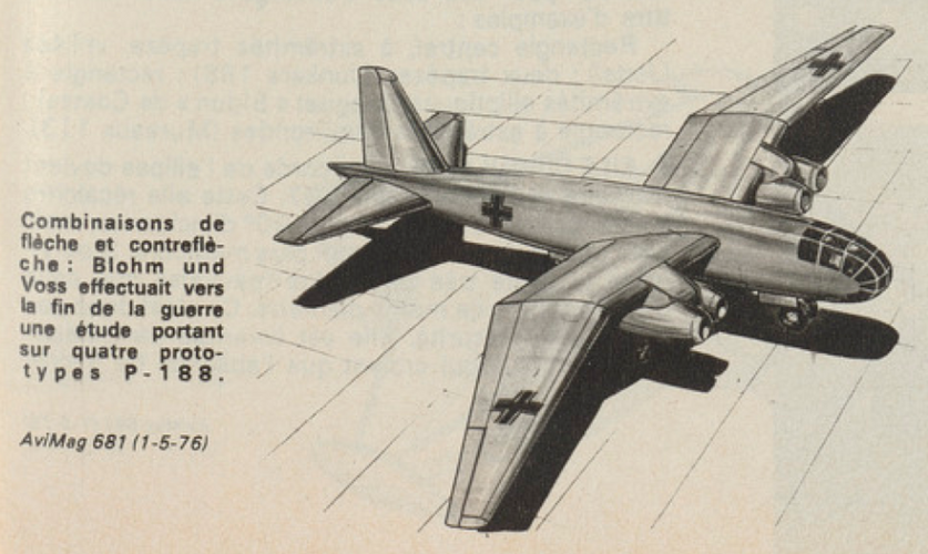
The variable incidence wing was originally conceived by him for his flying boats so that the fuselage would have the correct position to the water surface during landing independent of the angle of approach of the wing. This is critical because the touch down of the tail in the water could generate a momentum to cause the aircraft nose to dive into the water during landing. The implementation of the variable incidence wing was facilitated by the typical wing construction method of Vogt - using one strong hollow steel spar for the wing which was at the same time the axle of rotation for the wing.
Another field of application for the variable incidence wing is when tandem (bicycle) landing gear has been used.
There are many advantages of bicycle gear for bombers - like bigger and cleaner bomb bay and less pressure on tires. So, many early jet bombers had it. But there is one big difficulty, too. When using tandem gear, both gears (front/rear) are getting off the ground and landing at the same time ( to see when a B-52 takes off) . So there is no nose rotation - so how to produce lift, how to take off? An elegant solution is the use of variable incidence wings. The case for variable incidence wing has been really good explained in a book: Luftwaffe - Secret Bombers of the Third Reich by Dan Sharp (chapter on P.188)

There are less elegant solutions, too - B-47 had longer nose wheel, so while on ground, a nose is pointing up; B-52 has a permanent positive incidence of wings so it flies horizontally with a nose pointing down, some Soviet jets had two stage nose wheel, and so on..
 
Last edited:
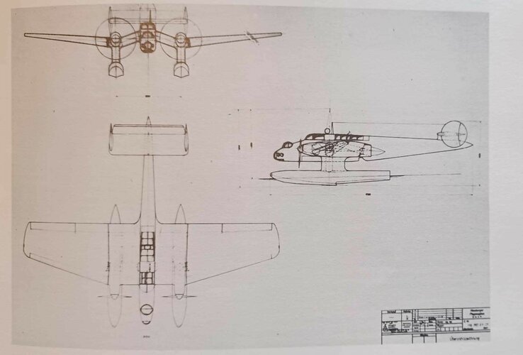
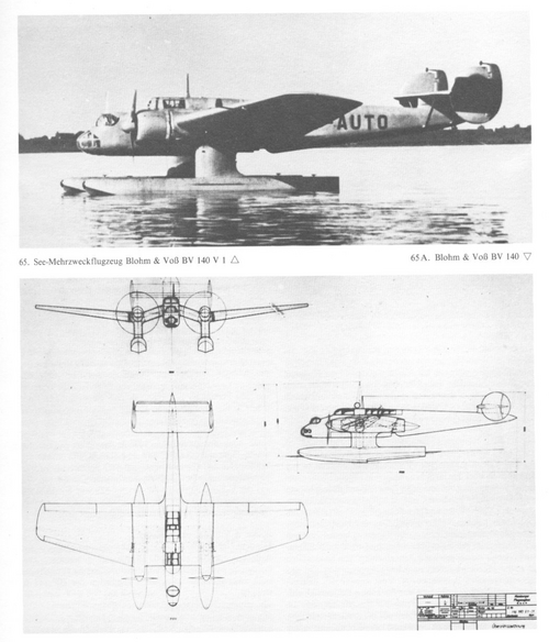
Here a drawing of Blohm And Voss Ha 140 from Nowarra's last edition book. The drawing is labelled as Ha 140 V1-01.
4 things are different for me:
  1. Engine cowl looks like V-12 (instead BMW Radial 132)
  2. The fuselage is longer (exceed rudder)
  3. Rudder shape is different (round)
  4. Wing shape in W
The BV P.19 is listed with 2x Jumo 210, it can be an early drawing of Ha 140 indeed. Quite interesting.

Nowarra's specification:
Spann 21m (21.8m on the drawing for me)
Length 17.6m
Height 5.5m

V1 to V3 specification
Spann 22m
Length 16.75m
Height 5.9m
 

Attachments

  • 364546911_316793290762153_5057595883722412532_n.jpg
    364546911_316793290762153_5057595883722412532_n.jpg
    251.8 KB · Views: 378
Last edited:
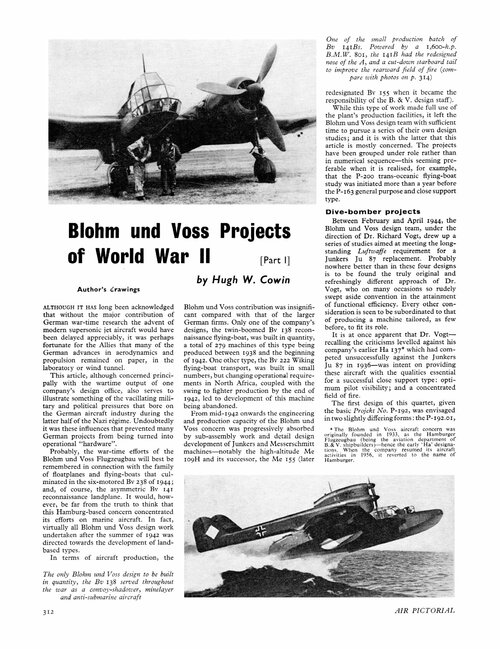
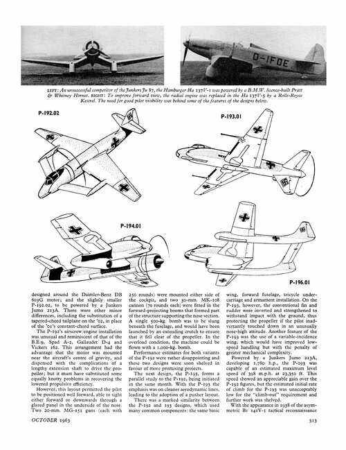
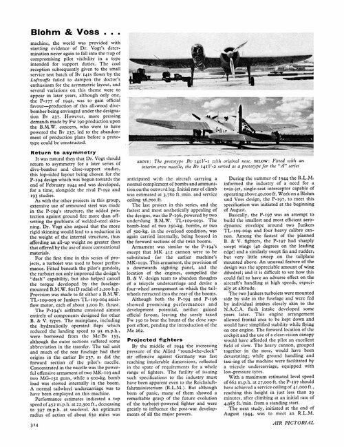
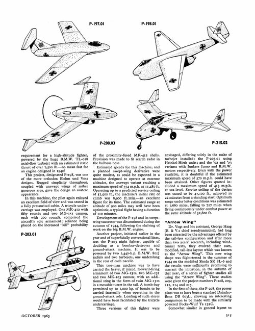
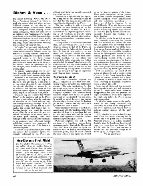
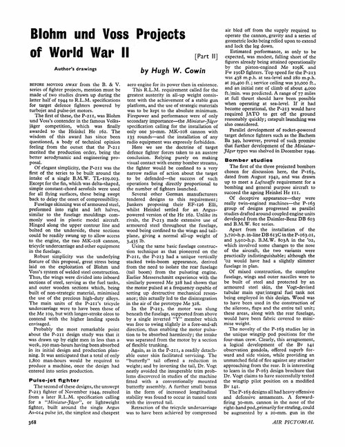
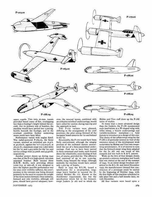
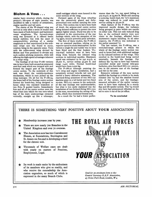
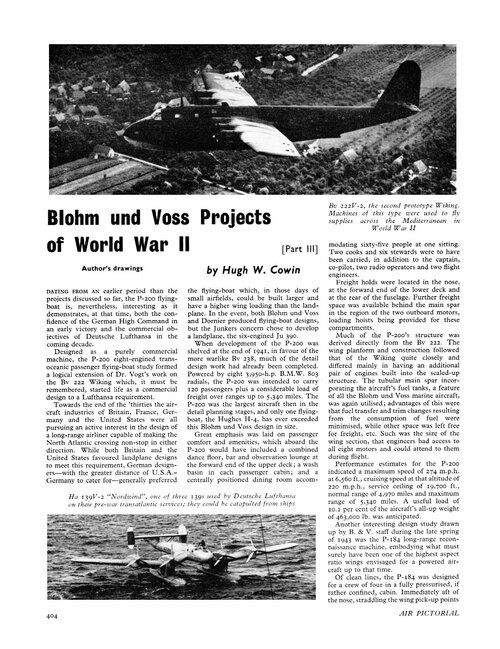
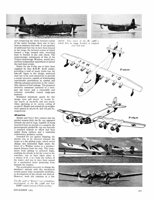
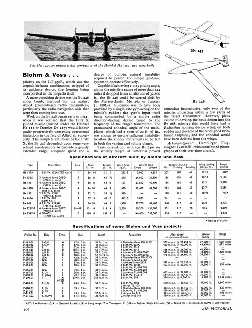
From Air Pictorial 1963.
 

Attachments

  • 1.jpg
    1.jpg
    805.1 KB · Views: 279
  • 2.jpg
    2.jpg
    688.6 KB · Views: 261
  • 3.jpg
    3.jpg
    946.1 KB · Views: 257
  • 4.jpg
    4.jpg
    709.2 KB · Views: 252
  • 5.jpg
    5.jpg
    944.5 KB · Views: 235
  • 6.jpg
    6.jpg
    987.5 KB · Views: 251
  • 7.jpg
    7.jpg
    668.2 KB · Views: 251
  • 8.jpg
    8.jpg
    764.8 KB · Views: 248
  • 9.jpg
    9.jpg
    884.7 KB · Views: 238
  • 10.jpg
    10.jpg
    699.2 KB · Views: 251
  • 11.jpg
    11.jpg
    693.8 KB · Views: 270
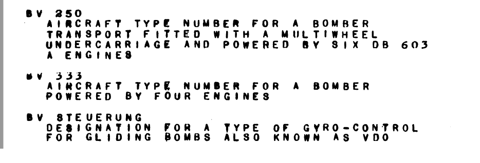
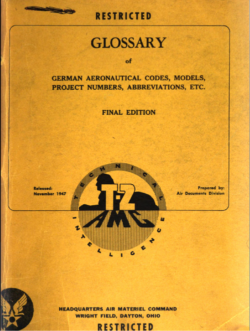
From this report,

a very strange projects (the lower two designs) ?,BV.333 Bomber ?.
 

Attachments

  • 1.png
    1.png
    35.6 KB · Views: 196
  • 0.png
    0.png
    1.8 MB · Views: 254
At least the lower one (BV Steuerung) is described as a gyro controlled flight control system, not an aircraft project.
 
Re the P.188.02

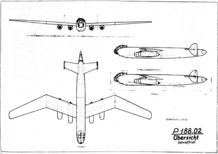
Are there any decent drawings of the main gears? I've got the Unicraft resin approximation (I cannot use the work "kit") and that indicates single wheel on a single leg in two separate positions either side of the fuselage. Even for Blohm und Voss, that's just plain stupid. The drawings I've seen are just not clear enough.
 
Hi,


from the book; Blohm & Voss Bv.138,by Heinz J. Nowarra,here is the Bv P.110,
and also the P.111 with a more info about P series,which was connected with
Bv.138.
Makes you wonder how BuV would have made those asymmetric planning surfaces work on a water landing. You have the long boat hull of the fuselage and a single outrigger. Hydraulic drag on those two surfaces would have been very different and asymmetric. On a normal flying boat, the hull and outriggers (where used) are symmetrical, so you don't have this issue. Here, you have the outrigger float on one side and it likely is going to cause the plane to pull towards it rather than go in a straight line. Probably not a good thing...
 
As long as the power is also asymmetrical, it's manageable. Just pay careful attention during splashdown. It could even be automated with a sensor in the pylon triggering more throttle or pitch on that engine.

Weird as it does look, it is less asymmetrical than the BV-141...
 
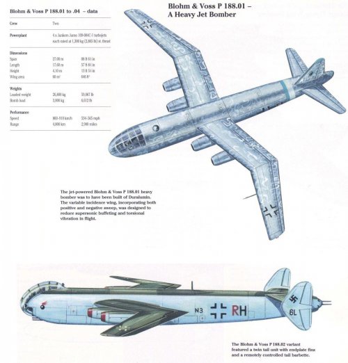
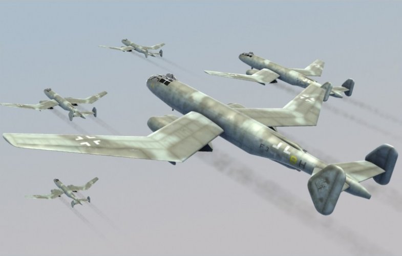
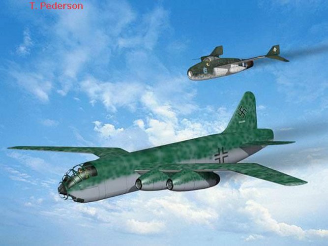
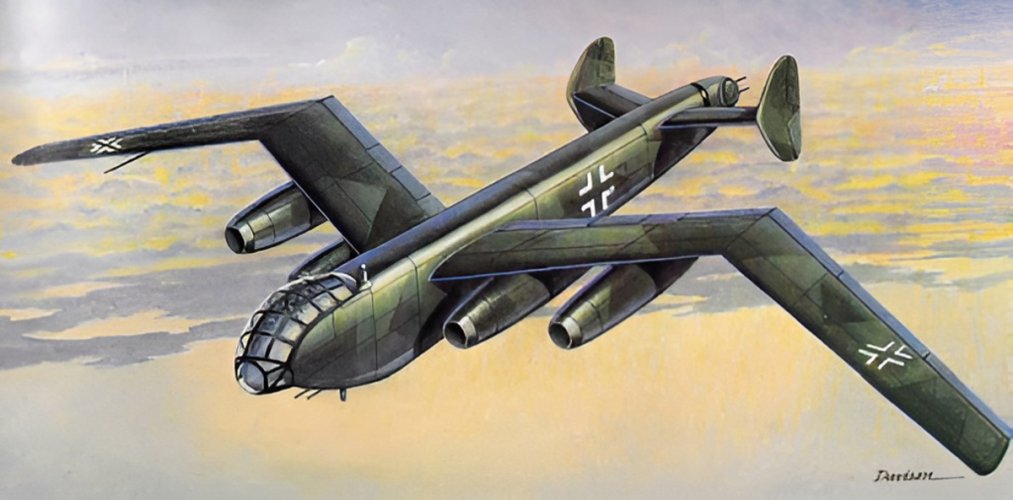
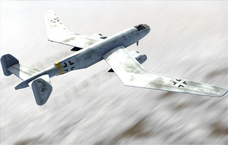
The Blohm & Voss Bv P 188 was a long-range, heavy jet bomber design project by the Blohm & Voss aircraft manufacturing division during the last years of the Third Reich. It featured a novel W-wing planform with variable incidence.
The project was rejected in favour of the Junkers Ju 287 and no aircraft was ever built.

P 188 Variants
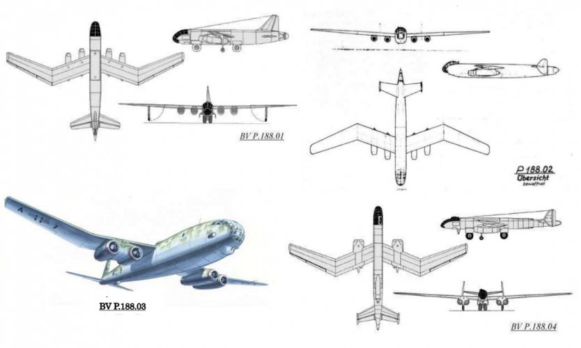
Four different variants of the P 188 were offered. The best arrangement for the four engines was unknown, so two different arrangements were offered. It was also believed that the high speed of the aeroplane would provide sufficient protection, so some variants were not fitted with defensive armament. The provision of guns and cannon on the other two variants affected the layout of the cabin and tail, and these variants would have had a lower top speed.
P 188.01
Four turbojets placed in separate nacelles under the wings. The tail section was of a conventional type and the projected speed was such that no defensive armament was carried.
P 188.02
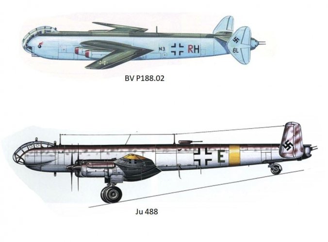
With a similar engine arrangement to the BV P.188 01, the 02 had twin tail fins to make room for a tail installation containing two MG-131 machine guns. The cockpit was also raised to accommodate two 20 mm MG-151 cannon in a nose turret. Two further MG-151s were installed under the rear fuselage.
P 188.03
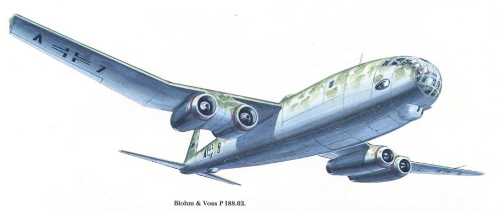
In the third variant, the outer engines were moved inboard next to the inner ones, creating a single paired installation on each side. This reduced drag and therefore increased speed. It also improved asymmetric handling in the engine-out situation. In other respects, the '03 was similar to the unarmed '01.
P 188.04
A long-range variant with a redesigned nose section to allow a slimmer fuselage, the '04 had additional steel fuel tankage in the fuselage and wings. These changes meant that the bomb load had to be carried externally, beneath the fuselage. Defensive armament comprised dorsal and ventral twin-machine-gun barbettes as well as nose and tail mounted twin 20 mm cannon installations. The twin tail was given added dihedral to angle it above the jet exhaust.
(Wikipedia)
http://www.flying-things.ch/blohmvoss.htmhttps://www.facebook.com/photo/?fbid=10157869466512260&set=pcb.1450588555297464
 

Attachments

  • P 188.jpg
    P 188.jpg
    199.2 KB · Views: 73
  • BV P.188-01 and -02.jpg
    BV P.188-01 and -02.jpg
    152.5 KB · Views: 68
  • BV P188-02.jpg
    BV P188-02.jpg
    51.3 KB · Views: 69
  • 481450579_10160537611062260_3302444398721169294_n.jpg
    481450579_10160537611062260_3302444398721169294_n.jpg
    46.4 KB · Views: 63
  • bvp188-03.jpg
    bvp188-03.jpg
    192.1 KB · Views: 61
  • p 188-04.jpg
    p 188-04.jpg
    39.1 KB · Views: 69
Last edited:
Hi!
 

Attachments

  • p 188-01.jpg
    p 188-01.jpg
    324 KB · Views: 63
  • p 188-02 (2).jpg
    p 188-02 (2).jpg
    543.3 KB · Views: 63
  • p 188-02.jpg
    p 188-02.jpg
    146.3 KB · Views: 64
  • p 188-04.jpg
    p 188-04.jpg
    343.4 KB · Views: 80
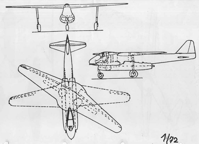
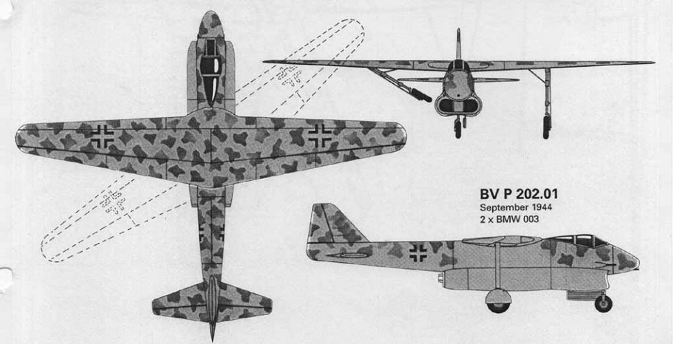
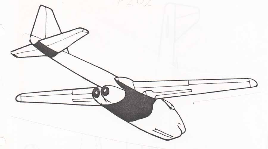
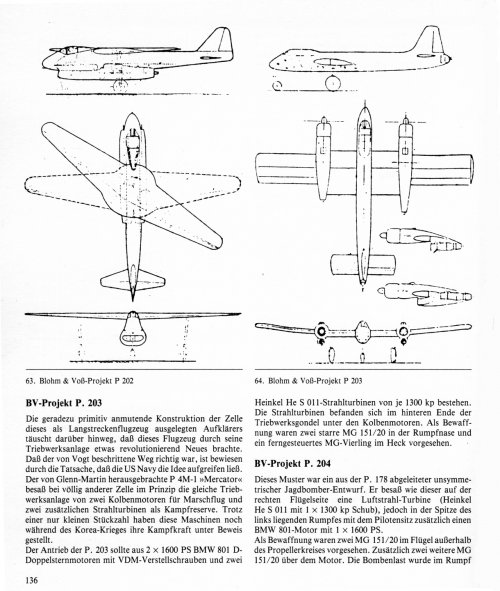
Hi! P 202.
https://www.modellboard.net/index.php?topic=69839.0
The Blohm & Voss P.202 was an unusual design study for a variable-geometry jet fighter during World War II. It was the first design to incorporate a slewed wing (also known as an oblique or scissor wing) in which one side swept forward and the other back. The P.202 was never built or flown.

Design​

The high speeds attainable by jet aeroplanes led German workers to develop the swept wing, in order to minimise the problems met as the speed of sound was approached. But sweeping the wings causes problems of its own, especially at the low speeds used for takeoff and landing. A variable-sweep mechanism was one possible solution but it would be complex, heavy and expensive. It also has problems with movement of the centre of lift. Both backwards and forwards sweep were investigated and they proved to have opposite disadvantages. Sweeping one wing forwards and the other back would balance out the aerodynamic problems and a one-piece slewed wing approach would not need such a complex sweep mechanism.

The P.202 jet fighter project emerged as Blohm & Voss designer Richard Vogt's ingenious solution.[2] Conventional in other respects, the high-mounted wing could be slewed by up to 35° for high-speed flight. The wing span was 12.0 metres (39.4 ft) when unswept and 10.0 metres (32.8 ft) when fully swept.

The long main undercarriage retracted into the wing, while a nose wheel completed the tricycle undercarriage.
The P.202 was powered by a pair of BMW 003 turbojets, slung underneath the fuselage centre section and exhausting behind the wing.
Provision for three forward-firing cannon was made in the nose.(Wikipedia)
 

Attachments

  • P202-01.jpg
    P202-01.jpg
    75.3 KB · Views: 61
  • P202-01 (2).jpg
    P202-01 (2).jpg
    67.5 KB · Views: 57
  • P202.jpg
    P202.jpg
    40.4 KB · Views: 54
  • 641.jpg
    641.jpg
    790 KB · Views: 73
Last edited:
Thanks! Additional fuel tank?
Anyway beautiful artwork‼️
 
Hi! My understanding was as follows.
But perhaps there were no room for fuel tank.
 

Attachments

  • BV 208.01.JPG
    BV 208.01.JPG
    162.2 KB · Views: 59
Last edited:
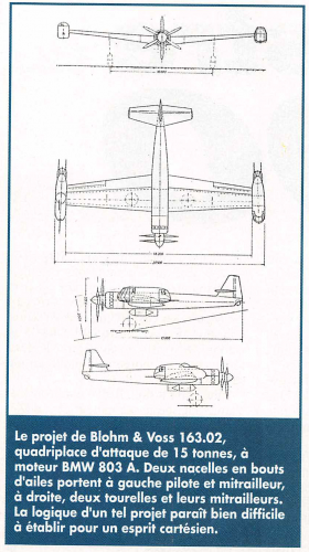
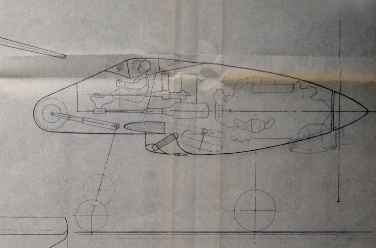
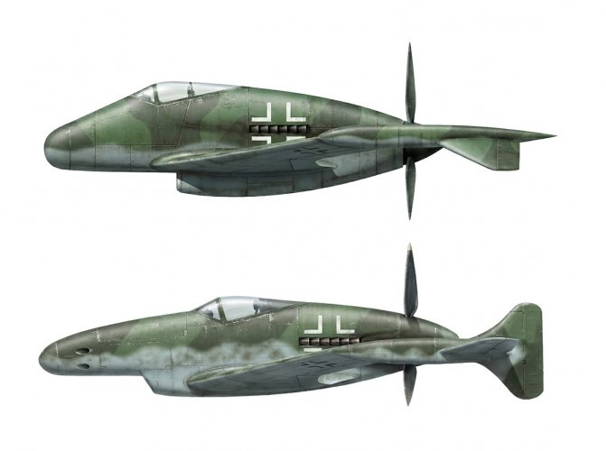
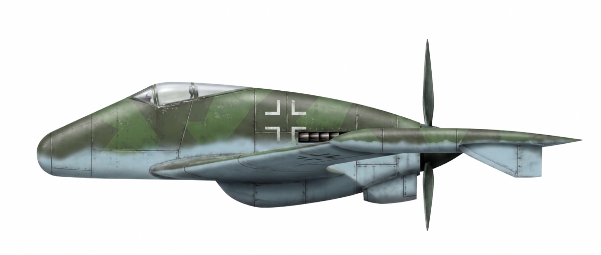
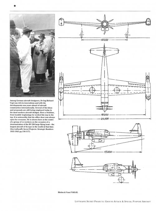
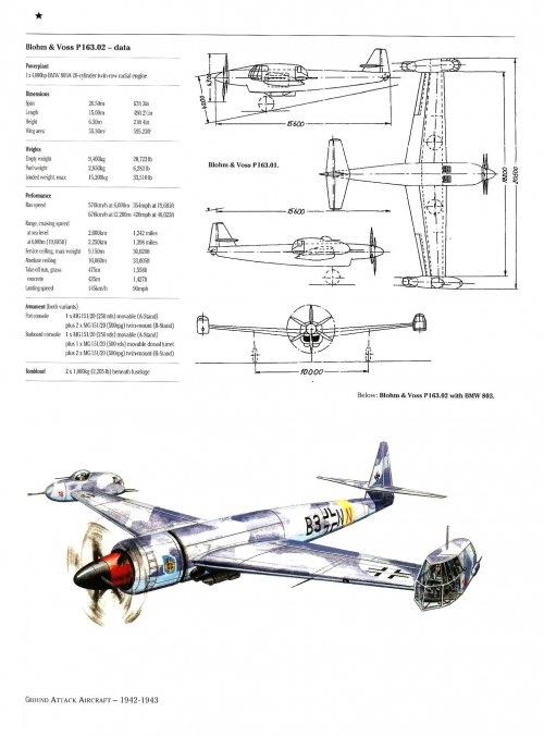
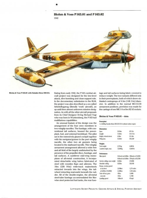
Hi! P.163-01 DB 613 and P.163-02 BMW 803.
Source ; Facebook.
 

Attachments

  • BV P163-02.jpg
    BV P163-02.jpg
    216.5 KB · Views: 42
  • BV P163-02 BMW 803.jpg
    BV P163-02 BMW 803.jpg
    239.3 KB · Views: 45
  • BV P163-01 DB613.jpg
    BV P163-01 DB613.jpg
    278.2 KB · Views: 57
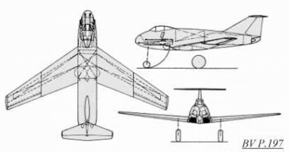
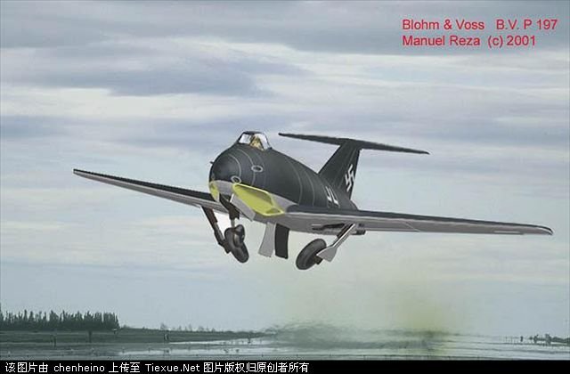
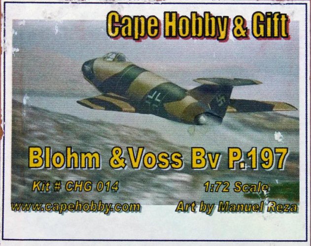
Hi! P.197.
https://war-book.ru/blohm-und-voss-p-197-istrebitel/

"The only very clean aerodynamic design for a fighter with two jet engines, similar to those that powered the Me 262​

The only truly aerodynamically clean fighter design with two jet engines, similar to those powering the Me 262. Hamburg's representatives demonstrated, at least in their calculations, that the Me 262's performance, especially its speed, could be significantly improved by using modern aerodynamics. It was unclear, given the somewhat challenging air intake situation, how the designers intended to improve the lift of the swept wing at low speeds, as the surviving original drawings show no auxiliary devices such as flaps or flaps. The aircraft's layout clearly resembles that of many successful post-war aircraft.

Powerplant: 2 x Jumo 109-004 with static thrust of 890 kg each or 2 x BMW 109-003 with static thrust of 800 kg
each Wingspan: 11,100 mm,
sweep: 35 degrees along the 1/4 chord line
Wing area: 20.5 sq.m,
Aspect ratio: 6.0 m
Overall length: 9,000 mm
Maximum height: 3,640 mm
Takeoff weight: 7,100 kg (with Jumo 004)
Max. Specific wing loading: 346 kg/m2
Maximum speed: 1060 km/h at an altitude of 8 km
Rate of climb at ground level: 21 m/sec (an altitude of 10 km was reached in 10.1 min)
Service ceiling: 12,500 m
Armament: 2 x MK 103, 30 mm caliber, and 2 x MG 151/15, 15 mm caliber."

https://www.facebook.com/Bruyneel.Patrick/posts/le-blohm-voss-p-197-était-un-projet-de-chasseur-monoplace-biréacteur-en-réponse-/1038275664998044/
https://live.warthunder.com/post/126701/en/
 

Attachments

  • 487205414_1663878157837652_1931240462322684122_n.jpg
    487205414_1663878157837652_1931240462322684122_n.jpg
    61.8 KB · Views: 49
  • 11384687.jpg
    11384687.jpg
    33.7 KB · Views: 50
  • P.197-1.jpg
    P.197-1.jpg
    145.5 KB · Views: 45
  • 00066005.jpg
    00066005.jpg
    62.9 KB · Views: 47
Last edited:

Similar threads

Back
Top Bottom