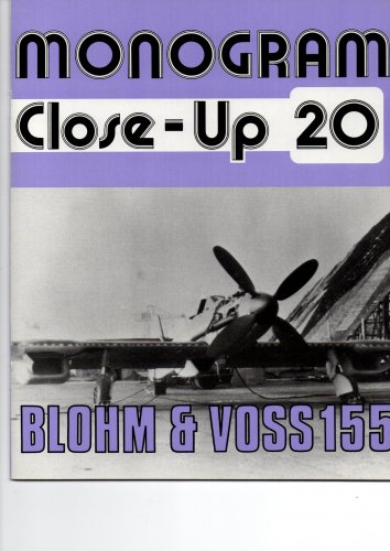
All the projects mentioned above are brainchilds of B & V's chief engineer Dr. Richard Vogt (also see wikipedia: Dr. Richard Vogt, aircraft designer), apart from the BV-155 which was originally a Messerschmitt design but was given to B & V because of work overload where it was revised by Vogt. Vogt was a real pioneer regarding new aerodynamic concepts and one can highly recommend to read his memoirs (Weltumspannende Memoiren eines Flugzeugkonstrukteurs [Global memoirs of an aircraft designer]) where he describes his ideas behind the concepts.

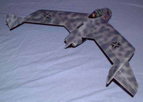
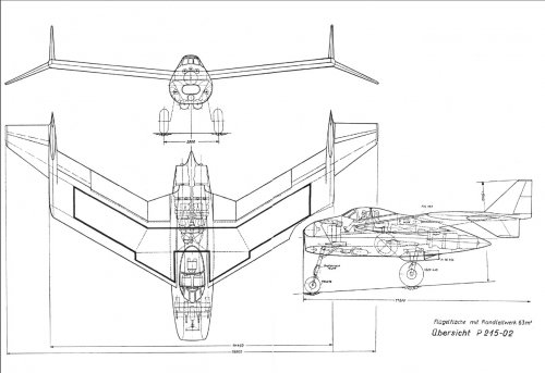
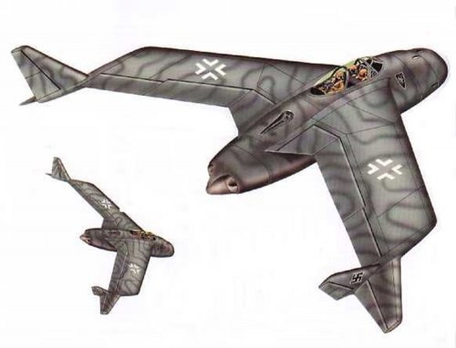
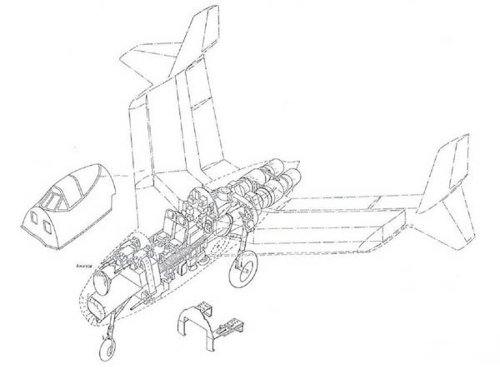
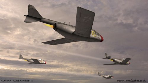
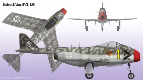
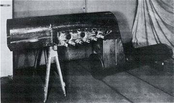
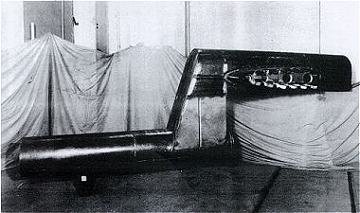
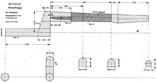
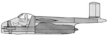
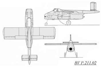
The variable incidence wing was originally conceived by him for his flying boats so that the fuselage would have the correct position to the water surface during landing independent of the angle of approach of the wing. This is critical because the touch down of the tail in the water could generate a momentum to cause the aircraft nose to dive into the water during landing. The implementation of the variable incidence wing was facilitated by the typical wing construction method of Vogt - using one strong hollow steel spar for the wing which was at the same time the axle of rotation for the wing. The usage of a strong backbone steel spar was also used by him for fuselage construction for all of his late-war fighter and ground attack projects. You can see this on the P 211 and P 213 where the rear part of fuselage simply consists of a tapered steel spar which also houses the fuel; this spar is extended to the aircraft nose in form of a gibbet which forms the air intake for the jet engine / pulse engine. Even the P 215 was constructed in that way although it is less obvious.

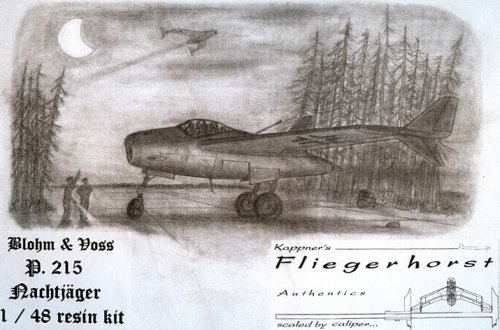
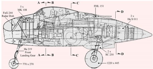
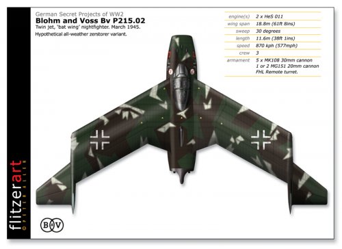
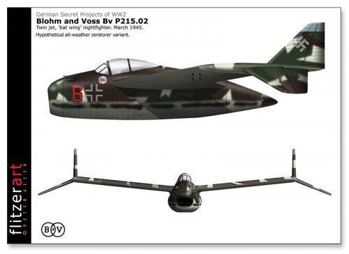
Jemiba, I also always wondered how the "Geradbahnschuss" was to be used on the P 215; I do not know of any other German project where it is mentioned. It was not intended to replace the "Schräge Musik" because this was installed additionally at the same time (I have a copy of the original P 215 presentation for the RLM). The P 215 was to use the latest electronic gear in radar search and aiming devices (it had a large search scanner above the intake and a smaller aiming scanner below and even the infrared FUG 280 scanner) and I am rather sure the angle for the weapons would have been changed automatically according to the distance and relative speed between the P 215 and the target.
 
Basil said:
one can highly recommend to read his memoirs (Weltumspannende Memoiren eines Flugzeugkonstrukteurs [Global memoirs of an aircraft designer]) where he describes his ideas behind the concepts.


Does anyone know if this has been translated into English?
 
Maybe an explanation for the "Geradbahnschuß" could be, that the P.215 would have been really fast
for its main prey, the British night bomber, so for a conventional attack with the forward firing weapons
time for aiming would have been quite short. The variable incidence wing could have slowed it down, but
the guns wouldn't have been aligned with the flight path, so a limited swivel range would have been useful.
 
GTX,
as far as I know Vogt has originally written his memoirs in English (he tells that in the intro of his book and he was living for more than 25 years in the USA then); I do not know if it was also ever published in English.

Jemiba,
the P 215 did not have a variable incidence wing. Another possibility for "Geradbahnschuß" could have been to extend the range of the very short barreled MK 108 with its low muzzle velocity by increasing the axis of the barrels in relation to the target. So the distance for opening the fire could have been extended considerably. Of course the elevation had to be calculated and adjusted automatically during the attack but this technology was ready in 1945.
 
Oops, sorry, got it mixed up. Probably because I was recently reading about the mostly futile attempts of the Luftwaffe at
the Eastern front and later USN/USMC to catch the Po-2 night intruders...
Were the principally similar (post war) experimental installations on the MiG 15 or Grumman Panther steplessly adjustable ?
 
Not sure about the MIG-15, but 99% sure concerning the Panther and the F-89 Scorpion.
 
Hi,


until I remember the source of some informations about projects from many companies,
at the end of the war,Blohm and Voss had a Project of all-weather night fighter,maybe
based on P.215 or developed from it ?.
 
hesham said:
until I remember the source of some informations about projects from many companies,
at the end of the war,Blohm and Voss had a Project of all-weather night fighter,maybe
based on P.215 or developed from it ?.


The Source;

"X-planes - German Luftwaffe Prototypes 1930-1945" by Manfred Griehl, Casemate 2012
 

Attachments

  • 0-1.png
    0-1.png
    76 KB · Views: 795
  • 1.png
    1.png
    28.7 KB · Views: 761
  • BV.png
    BV.png
    8.1 KB · Views: 779
A few BV profiles.
 

Attachments

  • 9BV208.jpg
    9BV208.jpg
    128.7 KB · Views: 722
  • BvP208.03:B.jpg
    BvP208.03:B.jpg
    102.5 KB · Views: 225
  • BvP208.03:C.jpg
    BvP208.03:C.jpg
    144.5 KB · Views: 192
  • BvP208.03:D.jpg
    BvP208.03:D.jpg
    113.9 KB · Views: 207
Neat! Thanks for sharing. One of my absolute favorite German projects.
 
Wouldn`t it be great if our top Blohm & Voss contributor, Kiradog, made an appearance? All input from you is most welcome, Gary!
 
Are there any good sources or books with more details on the swept wing variant of the p211?
 
A good 3-view drawing to BV P.163.02,
 

Attachments

  • 163.02.png
    163.02.png
    179.6 KB · Views: 257
Hi!
Source : internet as usual. ;D
 

Attachments

  • 210.jpg
    210.jpg
    10.5 KB · Views: 185
  • 20901.jpg
    20901.jpg
    6.7 KB · Views: 212
  • bv.jpg
    bv.jpg
    148.7 KB · Views: 224
Hi
side view.jpg (82.82 kb)
bv.jpg (148.74 kb)
210.jpg
21202.jpg
are Justo Miranda drawings ;)
sources Reichdreams Nº 15 and Monogram Close-up 20
 

Attachments

  • USN389.jpg
    USN389.jpg
    580.3 KB · Views: 134
  • USN388.jpg
    USN388.jpg
    744.8 KB · Views: 111
Thanks a lot Justo-san. Especially bv.jpg is Super!!! :D
P.215.02 all weather night fighter is a very large fighter.
She had radars, AAMs and protective armament. :eek:

https://www.youtube.com/watch?v=-9WdpX22Fjs
https://www.youtube.com/watch?v=3geYHIazLmo
Please enjoy RC model perfect flight. ;)
Landing strategy is excellent. ;D
 

Attachments

  • boxart.jpg
    boxart.jpg
    133.1 KB · Views: 134
  • bv215e.jpg
    bv215e.jpg
    43.9 KB · Views: 131
  • bv215d.jpg
    bv215d.jpg
    45.9 KB · Views: 157
  • 215 02.jpg
    215 02.jpg
    202.1 KB · Views: 168
  • unbenanntfidkznhub1.jpg
    unbenanntfidkznhub1.jpg
    254.1 KB · Views: 128
  • 215bp3.gif
    215bp3.gif
    27.2 KB · Views: 122
  • 215bp2.gif
    215bp2.gif
    23.3 KB · Views: 127
  • 215bp1.gif
    215bp1.gif
    27.6 KB · Views: 144
These aircraft realized small, material saving, good rear view, low drag and light weight fuselage keeping normal contrl characteristic by wing tip horizontal stabilizer and wing tip vertical stabilizer(P.212.03 and P.215.02).
Wing tip horizontal stabilizer and wing tip vertical stabilizer looks like winglet.
 
P.212.01 had little different wing shape.
P.212.03 shape is little strange for me.
It's possible to have normal tail horizontal and vertical stabilizer at the tail of the fuselage.
 

Attachments

  • 24-07-09_bvp2123.jpg
    24-07-09_bvp2123.jpg
    184.4 KB · Views: 161
  • 33-2.jpg
    33-2.jpg
    152.5 KB · Views: 147
  • Blohm-Voss_BV_P_212-03.jpg
    Blohm-Voss_BV_P_212-03.jpg
    159.3 KB · Views: 142
  • Blohm-Voss_BV_P_212-02.jpg
    Blohm-Voss_BV_P_212-02.jpg
    144.1 KB · Views: 137
  • 3bb21203.jpg
    3bb21203.jpg
    13.3 KB · Views: 131
  • 3bb21202.jpg
    3bb21202.jpg
    17.5 KB · Views: 142
  • 3bb21201.jpg
    3bb21201.jpg
    13.5 KB · Views: 145
These P.212.03 design had tail fin.
Source
http://www.luft46.com/bv/bvp212.html
 

Attachments

  • BV P212-03 armed with 22 R4M rockets and two MK 108 30mm cannon.jpg
    BV P212-03 armed with 22 R4M rockets and two MK 108 30mm cannon.jpg
    55.7 KB · Views: 139
  • BV P212-03 armed with SC 500 bomb and three MK 108 30mmm cannon.jpg
    BV P212-03 armed with SC 500 bomb and three MK 108 30mmm cannon.jpg
    60.7 KB · Views: 139
  • BV P212-03 armed with seven MK 108 30mm cannon.jpg
    BV P212-03 armed with seven MK 108 30mm cannon.jpg
    62.8 KB · Views: 144
P.212.03 design with SEVEN MK108 ?!
Firing 30 mm caliber shell makes that Jet plane a serious enemy

Although i think to spot a design fault,
The underbelly MK 108 rounds Magazine is close to Jet engine, A danger overheating the magazine ?
 
Michel Van said:
P.212.03 design with SEVEN MK108 ?!
Firing 30 mm caliber shell makes that Jet plane a serious enemy

Although i think to spot a design fault,
The underbelly MK 108 rounds Magazine is close to Jet engine, A danger overheating the magazine ?
Oh! :eek:
You mean this design?
 

Attachments

  • BV P212-03 armed with seven MK 108 30mm cannon.jpg
    BV P212-03 armed with seven MK 108 30mm cannon.jpg
    62.8 KB · Views: 162
JeffB said:
Terrific pictures, thanks for sharing Blackkite.
Thanks. I'm very happy to know that you enjoy my post. ;)
 
Hi!
Top P.215.02 picture which you post shows two guns in shoulder turret, but I think only one gun in shoulder turret based on detail line drawing.
Bottom picture of your post must be P.212.03 attacking U.S.Army vehicle.
 
blackkite said:
P.212.01 had little different wing shape.
P.212.03 shape is little strange for me.
It's possible to have normal tail horizontal and vertical stabilizer at the tail of the fuselage.

Hi, blackkite. Thanks for this post. Have You that 3-vews in better quality (hi-rez and bigger)?
 
Unfortunately I don't have that 3-viws in better quality (hi-rez and bigger).
I'm trying to get such a 3-views. BTW very hard. ;)
 
blackkite said:
Michel Van said:
P.212.03 design with SEVEN MK108 ?!
Firing 30 mm caliber shell makes that Jet plane a serious enemy

Although i think to spot a design fault,
The underbelly MK 108 rounds Magazine is close to Jet engine, A danger overheating the magazine ?
Oh! :eek:
You mean this design?

Yes that one
 
Hi! More 215 pictures. You can see a single cannon behind the cockpit.
 

Attachments

  • 215 pic3.jpg
    215 pic3.jpg
    106.6 KB · Views: 661
  • 215 pic1.jpg
    215 pic1.jpg
    89.8 KB · Views: 648
  • 215 pi2.jpg
    215 pi2.jpg
    69.9 KB · Views: 619
Hi conventional shape P.211/01. BTW fuselage tail strength is the problem.
The tortional strength of the fuselage is proportional to 4th power of a diameter. When a diameter will be 1/2, the strength falls to 1/16.
Of course you can use thick plate to recover strength, then weight increase. ;D
 

Attachments

  • ml211-8.jpg
    ml211-8.jpg
    53 KB · Views: 603
  • ml211-1.jpg
    ml211-1.jpg
    58.1 KB · Views: 616
I thought that the 211 used the same double steel tube construction of other designs, where the front tube is the intake and the rear is the tail which doubles as a fuel tank.

I've seen a drawing that shows the internals, but can't place where it is now. It could be an entirely fictional/speculative drawing.
 
Like this?

http://www.luft46.com/bv/bvp211ii.html

"This is the steel air-intake/fuselage load-bearing structure for the BV P.211.02, which as you can see was actually built!
Left: The air intake is on the left, the engine would attach at the right end of the bottom, round pipe.
Right: On the left is the fuselage structure, with the wing attachment point clearly visible. The cockpit would be located above the rounded air intake to the right. "

Steel structure, not alminum structure.!! Alminum saving? Heavy....
 

Attachments

  • bv211-1.gif
    bv211-1.gif
    28.5 KB · Views: 175
  • bvp212-6.jpg
    bvp212-6.jpg
    16 KB · Views: 149
  • bvp212-5.jpg
    bvp212-5.jpg
    17.8 KB · Views: 162
  • bv211-3.jpg
    bv211-3.jpg
    24.2 KB · Views: 167
  • bv211-4.jpg
    bv211-4.jpg
    6.4 KB · Views: 170
  • 3bb211ii.jpg
    3bb211ii.jpg
    5.9 KB · Views: 165
More 215 video.
https://www.youtube.com/watch?v=0dzIRBYHB0U
 
blackkite said:
Like this?

http://www.luft46.com/bv/bvp211ii.html

"This is the steel air-intake/fuselage load-bearing structure for the BV P.211.02, which as you can see was actually built!
Left: The air intake is on the left, the engine would attach at the right end of the bottom, round pipe.
Right: On the left is the fuselage structure, with the wing attachment point clearly visible. The cockpit would be located above the rounded air intake to the right. "

Steel structure, not alminum structure.!! Alminum saving? Heavy....

Yes, exactly like that.

This same idea was also employed on other b&h designs before the 211.

Structurally its very simple and not only saves on aluminum but also man hours. It may also not be all that bad in terms of weight as its taking all the loads of the fuselage.
 
Steel is stronger than alminum alloy.
So such a structure could be possible.
Thanks for lecture me. ;)
 
More P.212 versions:

Source: Kiradog
 

Attachments

  • P212-02-xx.jpg
    P212-02-xx.jpg
    81.9 KB · Views: 171
  • P212-01-01.jpg
    P212-01-01.jpg
    74 KB · Views: 178
Some profiles of some of the aircraft discussed plus a few more.
 

Attachments

  • BvP198Sw:A.jpg
    BvP198Sw:A.jpg
    138.8 KB · Views: 170
  • BvP198Sw:B.jpg
    BvP198Sw:B.jpg
    105.3 KB · Views: 165
  • BvP202:C.jpg
    BvP202:C.jpg
    123.6 KB · Views: 170
  • BvP202:D.jpg
    BvP202:D.jpg
    105.8 KB · Views: 141
  • BvP192.02:B.jpg
    BvP192.02:B.jpg
    116.5 KB · Views: 163
  • BvP192.02:A.jpg
    BvP192.02:A.jpg
    162.3 KB · Views: 566
  • BvP179:F.jpg
    BvP179:F.jpg
    159.2 KB · Views: 576
  • BvP179:E.jpg
    BvP179:E.jpg
    183.4 KB · Views: 601
  • BvP178:B.jpg
    BvP178:B.jpg
    167.5 KB · Views: 608
  • BvP178:A.jpg
    BvP178:A.jpg
    206.5 KB · Views: 623
And a few more
 

Attachments

  • BvP215.02:G.jpg
    BvP215.02:G.jpg
    196 KB · Views: 143
  • BvP210:D.jpg
    BvP210:D.jpg
    153.6 KB · Views: 135
  • BvP210:C.jpg
    BvP210:C.jpg
    183.9 KB · Views: 133
  • BvP209.02:D.jpg
    BvP209.02:D.jpg
    114.9 KB · Views: 139
  • BvP209.02:C.jpg
    BvP209.02:C.jpg
    141.4 KB · Views: 150
  • BvP215.02:H.jpg
    BvP215.02:H.jpg
    161.3 KB · Views: 150

Similar threads

Back
Top Bottom