
You are using an out of date browser. It may not display this or other websites correctly.
You should upgrade or use an alternative browser.
You should upgrade or use an alternative browser.
Me 262 - Projects, Pre-Projects And Variants


- Joined
- 26 May 2006
- Messages
- 38,285
- Reaction score
- 20,422
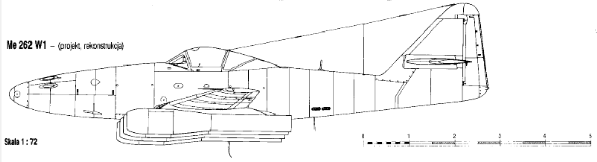
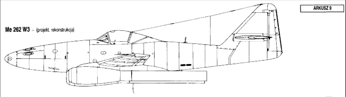
Any information on the Me 262 W1 and W3 variants? I could only find a few photos and models. Where these designs real or just fan art?
Of course they are a real designs,
https://en.wikipedia.org/wiki/Messerschmitt_Me_262
Attachments

Adler
Die Wunderwaffe
- Joined
- 27 February 2025
- Messages
- 223
- Reaction score
- 452
Any more information on these specific designs? What where the specifications, development and history if you know?
- Joined
- 26 May 2006
- Messages
- 38,285
- Reaction score
- 20,422
Any more information on these specific designs? What where the specifications, development and history if you know?
There is nothing more about them unfortunately.
- Joined
- 26 May 2006
- Messages
- 38,285
- Reaction score
- 20,422
Any more information on these specific designs? What where the specifications, development and history if you know?
http://users.telenet.be/denzjos/pulsejets/pulsejets.html
The Messerschmitt Me 262, also called 'Schwalbe', was the first operational fighter aircraft powered by jet engines. The aircraft was used to a limited extent by the Luftwaffe during the Second World War. The development of the Me 262 began before the war and the first plans were already on the table in April 1939. The test flights began in April 1941. After several adjustments, the Me 262 was ready for production in the course of 1942. Production did not start until 1944 when the engines delivered better performance. The Me 262 heralded the end of the era of propeller-driven fighters. The jet fighter could reach a top speed of 870 km/h, more than 150 km/h faster than other aircraft of the time and its four 30 mm cannons provided sufficient destructive power for attacks on bombers. The design was aerodynamically advanced, much more modern than its British counterpart the Gloster Meteor. The aircraft was 10.58 m long, had a wingspan of 12.5 m, was 3.83 m high and weighed 4,413 kg. Curiously enough, a variant of the Me 262 W was designed with the Argus pulse jet engine as power. Four pulse jets were fitted under each wing. This variant was not built
Attachments

Last edited:
- Joined
- 26 May 2006
- Messages
- 38,285
- Reaction score
- 20,422


Dagger
ACCESS: Secret
- Joined
- 24 December 2019
- Messages
- 412
- Reaction score
- 839
Some V555 stuff that was inserted in a second hand Me 262 book I once bought.
First is from unknown source. Rest is from 'Jet & Prop'.
First is from unknown source. Rest is from 'Jet & Prop'.
Attachments


Dagger
ACCESS: Secret
- Joined
- 24 December 2019
- Messages
- 412
- Reaction score
- 839
Another V555 photo from 'Jet & Prop'

The 110555 (V555) was the second Blitzbomber with a glazed nose.
The first one was the 110484 of which not many photos seem to exist. This is a partial one from 'Klassiker der Luftfahrt'


The 110555 (V555) was the second Blitzbomber with a glazed nose.
The first one was the 110484 of which not many photos seem to exist. This is a partial one from 'Klassiker der Luftfahrt'

Michael Förster
ACCESS: Restricted
- Joined
- 6 July 2025
- Messages
- 1
- Reaction score
- 4
Hallo.Ich bin neu.Triebwerke der Me 262 wurden bei mir in Zittau gebaut.Der RA 55 in der Uverlageung Seracit in Zgorzelec.
Dankeschön.
(Hello, I am new here. The engines of the Me 262 were built in Zittau, the RA 55 in the Uverlage Seracit in Zgorzelec.
Thank you very much.)
Dankeschön.
(Hello, I am new here. The engines of the Me 262 were built in Zittau, the RA 55 in the Uverlage Seracit in Zgorzelec.
Thank you very much.)

Grey Havoc
ACCESS: USAP
- Joined
- 9 October 2009
- Messages
- 24,500
- Reaction score
- 18,175
Hello. I'm new. The Me 262 engines were built here in Zittau. The RA 55 was built at the Seracit plant in Zgorzelec.
martinbayer
ACCESS: Above Top Secret
- Joined
- 6 January 2009
- Messages
- 5,081
- Reaction score
- 6,998
English, please. And I state that request as a German citizen.Hallo.Ich bin neu.Triebwerke der Me 262 wurden bei mir in Zittau gebaut.Der RA 55 in der Uverlageung Seracit in Zgorzelec.
Dankeschön.


- Joined
- 13 August 2007
- Messages
- 10,423
- Reaction score
- 18,114
one question
were to hell are Machine guns installed in those models ?

were to hell are Machine guns installed in those models ?


- Joined
- 11 June 2014
- Messages
- 1,641
- Reaction score
- 3,510
one question
were to hell are Machine guns installed in those models ?
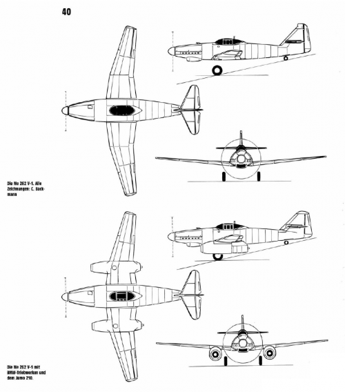
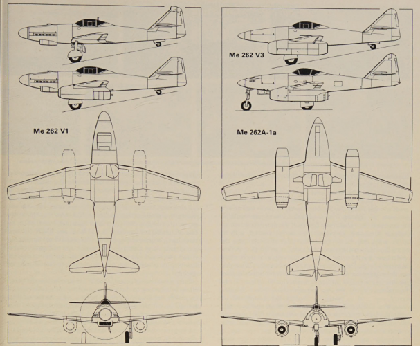
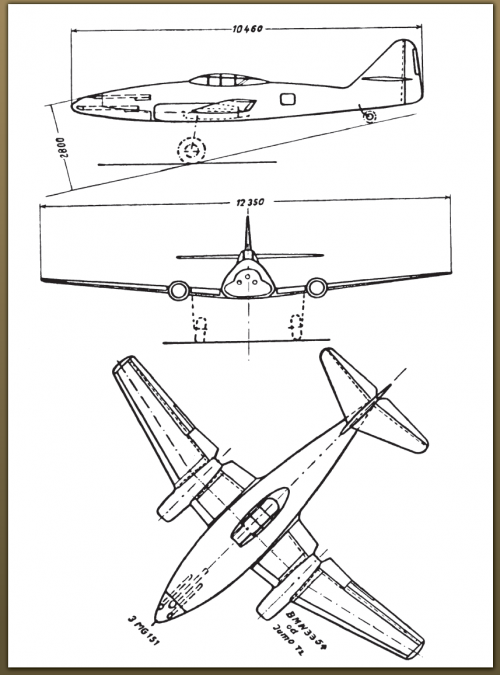
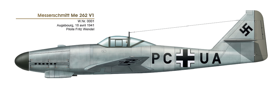
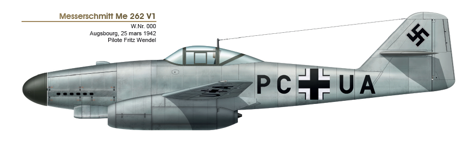
The image shows two versions of the same model - the experimental Me 262 V1. As Hood says, no weaponry was fitted because it was just a test airframe. The Me 262 V1 was initally flown without jet engines, using a Jumo 210 G in the nose, because the jets weren't available - but the aerodynamics of the airframe could still be tested.
When BMW jet engines were available, the Jumo 210 was left in the nose during the initial flight test - apparently as an insurance policy - although the flight test report doesn't mention it at all.
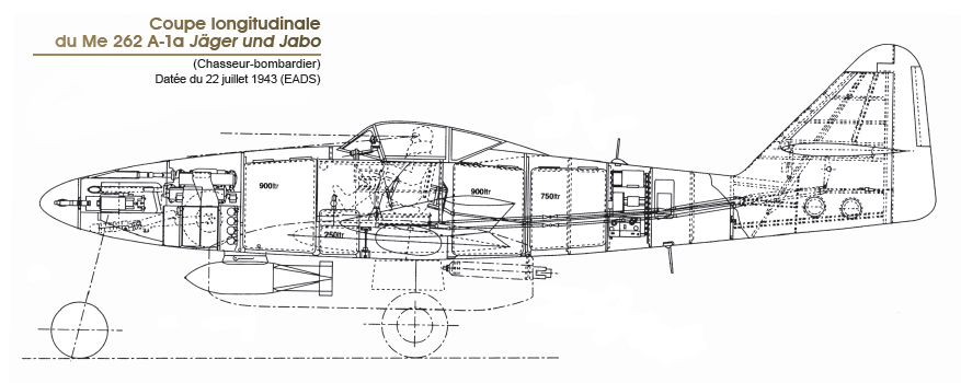
If, for the sake of argument, a piston engine had been part of the design and it was to have been a mixed propulsion fighter, they could've presumably stuck a DB 601 on there with an MG FF Motorkanone plus a couple of synchronised MG 17s in the engine cowling, firing through the prop arc.
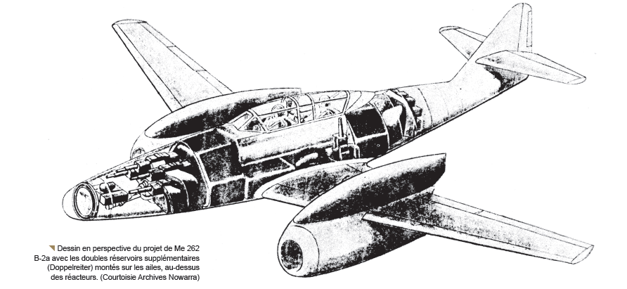
Later on, some work was done on the possibility of fitting armament into the space above the jet engine nacelles - which would've been outside the prop arc, had there been a prop - so that might also have been an option.
Source: Bundesarchiv
Signatur: RL 3/7914
Nov. 1944 - Me 262
ORIGINAL MESSERSCHMITT BROCHURE
https://invenio.bundesarchiv.de/invenio/direktlink/b48be25b-7977-4c09-9071-8904ec2aa042/[Click "DIGITALISAT ANZEIGEN " TO VIEW THE FILE]
ME 262
- A-1 U1 Jäger
- A-2 Blitzbomber
- A-3 Schnellstbomber
- A-4 Aufklärer
- B-1 Schulflugzeug
- C-1 Heimatschützer I*
- C-2 Heimatschützer II*
- Schleppbombe - Schleppbehälter
(*Note the "abwerfbare Zusatzräder 600×190" - jettisonable wheels)
Flugübungsgerät 8-262
(Me-262 Flight Simulator)
Die Vorarbeiten für das erste Gerät sind soweit fortgeschritten, daß die erste Plattform einschließlich Rumpf innerhalb der ersten Aprilwoche in Betrieb genommen werden kann.
(Preparatory work for the first device has progressed to the point that the first platform, including the fuselage, can be put into operation within the first week of April.)
Source:
WAR DIARY CHEF TLR
16.03.1945 - 04.04.1945
Signatur: RL 3/7914
Nov. 1944 - Me 262
ORIGINAL MESSERSCHMITT BROCHURE
https://invenio.bundesarchiv.de/invenio/direktlink/b48be25b-7977-4c09-9071-8904ec2aa042/[Click "DIGITALISAT ANZEIGEN " TO VIEW THE FILE]
ME 262
- A-1 U1 Jäger
- A-2 Blitzbomber
- A-3 Schnellstbomber
- A-4 Aufklärer
- B-1 Schulflugzeug
- C-1 Heimatschützer I*
- C-2 Heimatschützer II*
- Schleppbombe - Schleppbehälter
(*Note the "abwerfbare Zusatzräder 600×190" - jettisonable wheels)
Flugübungsgerät 8-262
(Me-262 Flight Simulator)
Die Vorarbeiten für das erste Gerät sind soweit fortgeschritten, daß die erste Plattform einschließlich Rumpf innerhalb der ersten Aprilwoche in Betrieb genommen werden kann.
(Preparatory work for the first device has progressed to the point that the first platform, including the fuselage, can be put into operation within the first week of April.)
Source:
WAR DIARY CHEF TLR
16.03.1945 - 04.04.1945
Last edited:
Me 262 with wingtip mounted FuG 248 "Eule"
[CLICK "DIGITALISAT ANZEIGEN" TO VIEW THE FILE]
Signatur: RL 3/6161
https://invenio.bundesarchiv.de/invenio/direktlink/e9b2d45e-de05-42af-b370-ce127e9b6612/März 1945 Einbauvorschlag für "Eule" in 8-262
[CLICK "DIGITALISAT ANZEIGEN" TO VIEW THE FILE]
Signatur: RL 3/6161
https://invenio.bundesarchiv.de/invenio/direktlink/e9b2d45e-de05-42af-b370-ce127e9b6612/März 1945 Einbauvorschlag für "Eule" in 8-262


Heavily armed Me 262 Part.1
March 12, 1945 [1]
"The Führer has again ordered that special emphasis be placed on the anti-aircraft ammunition and the heavy armament of the 8-262 (5cm - 6 x 10⁸, 2 or 4 x 3.7 cm 43)."
March 13, 1945 [2]
Development status
-Installation: MK 214 in 8-262
-Installation: 6 MK 108 in 8-262
-Installation: MK 112 in 8-262
March 15, 1945 [3]
Letter to Messerschmitt
Examination of the feasibility of installing the 3.7cm Flak 43 in the Me 262. Prototype installations for at least two 3.7cm Flak 43s have been commissioned. The weapon design documents can be obtained from Rheinmetall-Borsig AG, WKW Director Herlach, Unterlüss. Please submit the installation proposal and schedule for the design and prototype installations immediately to the Chef TLR.
March 22, 1945 [4]
Me 262 with 5cm, 2x 3.7cm and R4M
Source:
Bundesarchiv Files
[1] Signatur: RL 3/2567; Page: 269
[2] Signatur: RL 3/2583; Page: 36 - 40
[3] Signatur: RL 3/2583; Page: 10-12
[4] Signatur: R 3/1511; Page: 28
March 12, 1945 [1]
"The Führer has again ordered that special emphasis be placed on the anti-aircraft ammunition and the heavy armament of the 8-262 (5cm - 6 x 10⁸, 2 or 4 x 3.7 cm 43)."
March 13, 1945 [2]
Development status
-Installation: MK 214 in 8-262
-Installation: 6 MK 108 in 8-262
-Installation: MK 112 in 8-262
March 15, 1945 [3]
Letter to Messerschmitt
Examination of the feasibility of installing the 3.7cm Flak 43 in the Me 262. Prototype installations for at least two 3.7cm Flak 43s have been commissioned. The weapon design documents can be obtained from Rheinmetall-Borsig AG, WKW Director Herlach, Unterlüss. Please submit the installation proposal and schedule for the design and prototype installations immediately to the Chef TLR.
March 22, 1945 [4]
Me 262 with 5cm, 2x 3.7cm and R4M
Source:
Bundesarchiv Files
[1] Signatur: RL 3/2567; Page: 269
[2] Signatur: RL 3/2583; Page: 36 - 40
[3] Signatur: RL 3/2583; Page: 10-12
[4] Signatur: R 3/1511; Page: 28
Last edited:


Me 262 Variants - Original Drawings & Documents
Me 262 Leistungssteigerung - February 1945 - HG Variants
https://aerospace-jack.com/docs004.htm
Me 262 B-2 Nightfighters (Deutsche Lufthansa), Bomb loads, 1945 Painting Instruction, etc.
https://aerospace-jack.com/docs005.htm
Me 262 Lorin
https://aerospace-jack.com/docs007.htm
Source:
Jack's Aerospace History Files by Uwe W. Jack
https://aerospace-jack.com/index.htm
Me 262 Leistungssteigerung - February 1945 - HG Variants
https://aerospace-jack.com/docs004.htm
Me 262 B-2 Nightfighters (Deutsche Lufthansa), Bomb loads, 1945 Painting Instruction, etc.
https://aerospace-jack.com/docs005.htm
Me 262 Lorin
https://aerospace-jack.com/docs007.htm
Source:
Jack's Aerospace History Files by Uwe W. Jack
https://aerospace-jack.com/index.htm
Adler
Die Wunderwaffe
- Joined
- 27 February 2025
- Messages
- 223
- Reaction score
- 452

blackkite
Don't laugh, don't cry, don't even curse, but.....
- Joined
- 31 May 2007
- Messages
- 9,515
- Reaction score
- 9,661
https://alternathistory.ru/glavnyj-samolet-villi-messershmitta-ot-projeck-p65-do-me-262/
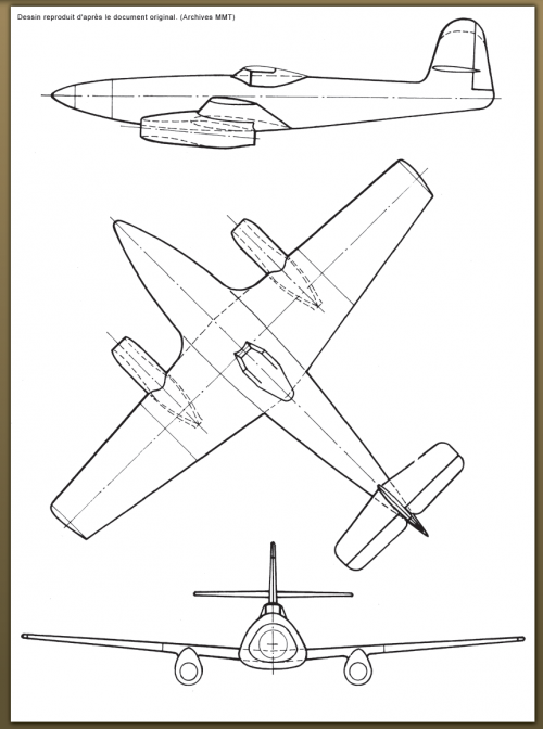
Meanwhile, in September 1939, the Messerschmitt design bureau, headed by Walter Rethel, began work on the P 1065 project and began preparations for the creation and submission of drawings for the production facilities. On November 9, 1939, Messerschmitt submitted an improved design proposal, No. 1 (Projektangebot I), to the RLM, and on December 19, 1939, the first official inspection of the mockup of the future aircraft took place, which passed without any significant criticism.
On March 1, 1940, Messerschmitt received an official order for three prototypes and one static test airframe. On the same day, the equipment specifications for the first prototype, the P 1065 V-1, were determined. The aircraft was to feature airbrakes, self-sealing fuel tanks, a drag parachute, a pressurized, non-pressurized cabin, and, most notably, a Heinkel ejection seat.
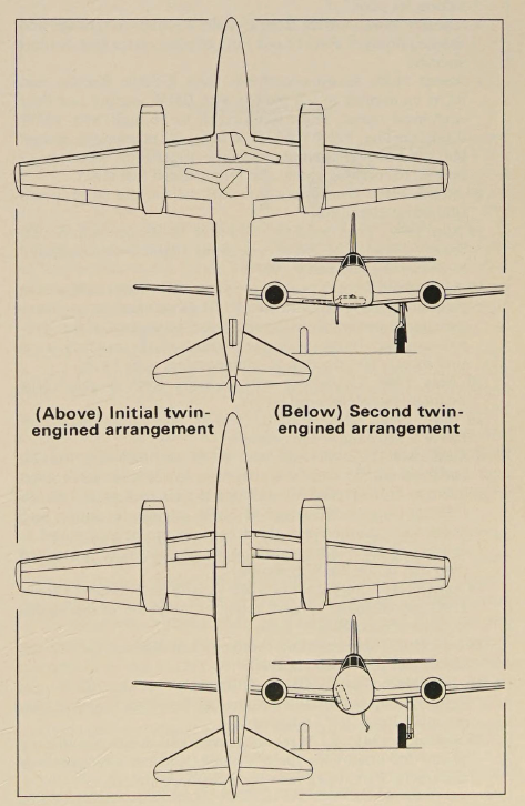
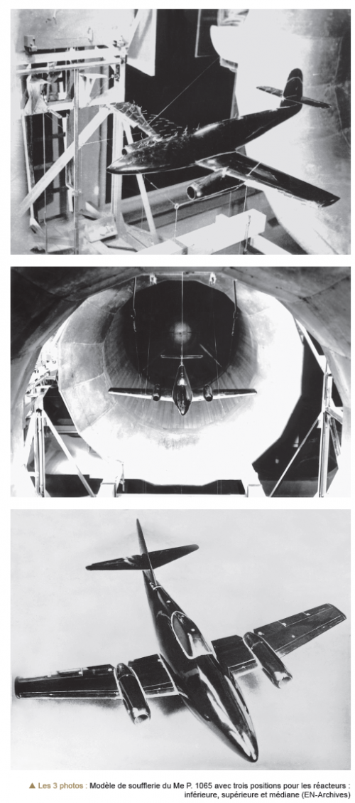
The second major change concerned the engine installation. For a long time, Messerschmitt design engineers favored placing the engines within the wing panels, a rather complex design. However, the aerodynamic advantages seemed to justify this additional effort, but as the weight and volume of BMW turbojet engines increased, the decision was made to abandon the internal mounting. All attention was focused on placing the engines in nacelles beneath or above the wing panels. Extensive wind tunnel research was conducted, and although the final configuration remained unclear for a long time, the design and production of tooling for the first two prototypes proceeded at the same pace. The final layout, with the engines placed in nacelles beneath the wing panels, ensured aerodynamic cleanliness on the upper wing surfaces and also ensured smooth airflow around the lower fuselage. The distance between the nacelles was large enough due to the fuselage being mounted above the wing centre section, thereby significantly reducing the harmful effects of interference.
From May 30, 1940 to April 4, 1941, the final transfer of the project (III) to the design bureau took place, and in February 1941, the P 1065 project received the official type designation 8-262 in the RLM.
Willy Messerschmitt reluctantly accepted the final version of the P 1065 design. He didn't immediately accept deviations from his optimal concept, particularly regarding the engine nacelle arrangement. Yet, Messerschmitt later called the Me 262 his most important aircraft, as no other of his designs would have led to so many important discoveries in the field of aviation technology!"
"High-speed wing aerofoil and deflecting leading edge
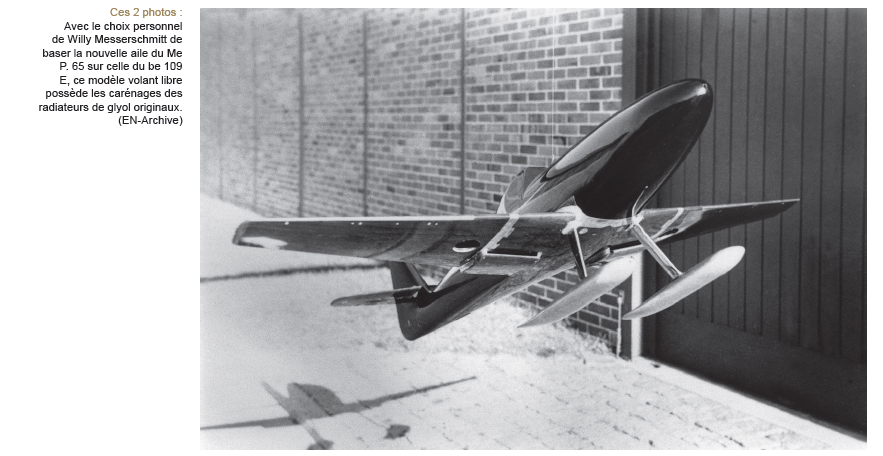
By placing the main landing gear wheels within a relatively wide, triangular fuselage, the wing panels could be relatively thin and light, thereby enabling high flight speeds. Between 1939 and 1941, a series of tests were conducted at the AVA to determine the optimal wing aerodynamic profile. During these studies, Ludwig Bölkow earned his first laurels. He calculated and developed what would later become a popular high-speed airfoil, designated the 009-E4. After the end of World War II, this airfoil was used in the wing of the North American F-86 Sabre fighter. Ludwig Bölkow proposed making the Me 262 fighter's wing as thin as possible: he chose a 9% relative airfoil thickness at the wing roots instead of the originally planned 12%. At the wingtips, the relative wing thickness decreased to 6%. However, Willy Messerschmitt had serious doubts about the feasibility of accommodating leading edge slats within such a thin wing. Such a thin wing lacked even the space for the main landing gear. Ludwig Bölkow soon developed a technical solution in the form of a deflecting leading edge flap (the so-called Kippnase), which he patented and steadily developed. Ultimately, however, Bölkow's ideas were not implemented in the Me 262 design. Too many innovations could have provoked objections from the responsible and technically very conservative RLM staff, and so the aircraft's wing had a relative thickness of 12% and conventional leading edge slats.Meanwhile, in September 1939, the Messerschmitt design bureau, headed by Walter Rethel, began work on the P 1065 project and began preparations for the creation and submission of drawings for the production facilities. On November 9, 1939, Messerschmitt submitted an improved design proposal, No. 1 (Projektangebot I), to the RLM, and on December 19, 1939, the first official inspection of the mockup of the future aircraft took place, which passed without any significant criticism.
On March 1, 1940, Messerschmitt received an official order for three prototypes and one static test airframe. On the same day, the equipment specifications for the first prototype, the P 1065 V-1, were determined. The aircraft was to feature airbrakes, self-sealing fuel tanks, a drag parachute, a pressurized, non-pressurized cabin, and, most notably, a Heinkel ejection seat.
Swept wing consoles
Meanwhile, two significant changes occurred during the development of the prototype's design. The BMW engines turned out to be larger and heavier than the engine engineers had anticipated, even with their less optimistic assumptions. This shouldn't be surprising, as turbojet engines were a new field of engineering and technology. However, these changes created serious problems for Messerschmitt, as they resulted in a shift in the P 1065's center of gravity. As development progressed, the wing sweep was increased as an emergency solution to the shift in the center of gravity. It's worth noting that at that point, no one in the Messerschmitt design bureau yet understood the advantages of swept wings for this speed range. Thus, a simple coincidence led to the Me 262 becoming the world's first jet fighter with swept wings! In May 1940, Messerschmitt submitted a modified design to the RLM as Improved Design Proposal No. 2 (Projektangebot II).The second major change concerned the engine installation. For a long time, Messerschmitt design engineers favored placing the engines within the wing panels, a rather complex design. However, the aerodynamic advantages seemed to justify this additional effort, but as the weight and volume of BMW turbojet engines increased, the decision was made to abandon the internal mounting. All attention was focused on placing the engines in nacelles beneath or above the wing panels. Extensive wind tunnel research was conducted, and although the final configuration remained unclear for a long time, the design and production of tooling for the first two prototypes proceeded at the same pace. The final layout, with the engines placed in nacelles beneath the wing panels, ensured aerodynamic cleanliness on the upper wing surfaces and also ensured smooth airflow around the lower fuselage. The distance between the nacelles was large enough due to the fuselage being mounted above the wing centre section, thereby significantly reducing the harmful effects of interference.
From May 30, 1940 to April 4, 1941, the final transfer of the project (III) to the design bureau took place, and in February 1941, the P 1065 project received the official type designation 8-262 in the RLM.
Willy Messerschmitt reluctantly accepted the final version of the P 1065 design. He didn't immediately accept deviations from his optimal concept, particularly regarding the engine nacelle arrangement. Yet, Messerschmitt later called the Me 262 his most important aircraft, as no other of his designs would have led to so many important discoveries in the field of aviation technology!"
Attachments
-
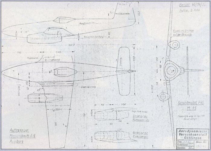 A drawing of the P 1065 wind tunnel test model, dated July 5, 1940. The trapezoidal straight w...jpg624.3 KB · Views: 79
 -
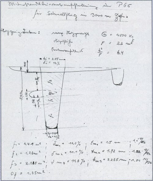 A sketch of the P 65 (P 1065) from the design team's first aerodynamic calculations. The sketc...jpg567.1 KB · Views: 71
 -
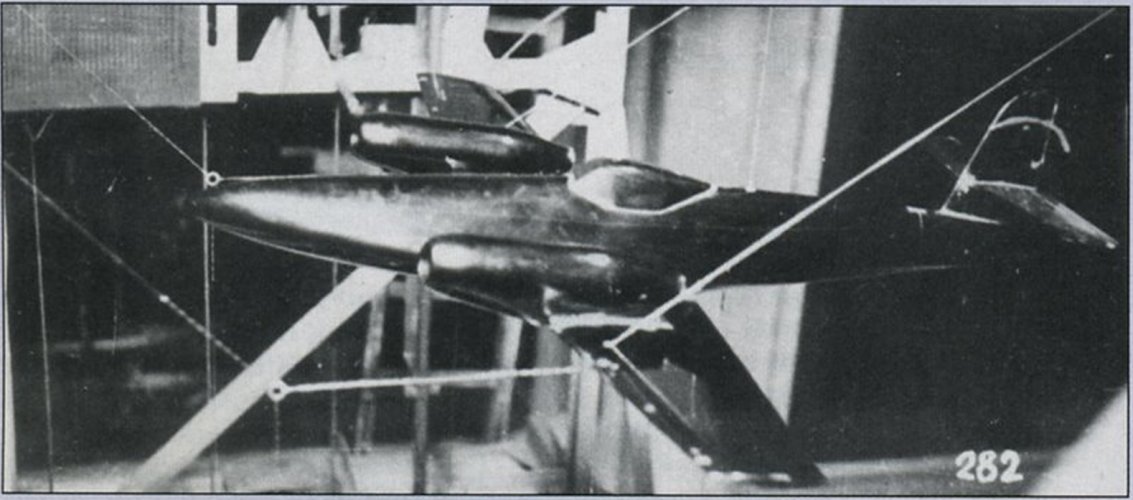 P 1065 wind tunnel test model with upper wing nacelles.jpg217.2 KB · Views: 61
 -
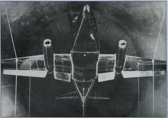 Vom-Projeck-P65-zur-Me-262-10.jpg306.3 KB · Views: 63
Last edited:
martinbayer
ACCESS: Above Top Secret
- Joined
- 6 January 2009
- Messages
- 5,081
- Reaction score
- 6,998
Anyone ever came across any documented verified sustained flight designs/schemes/delusions of any supersonic, let alone hypersonic (no Saenger glider need apply!) German pre 1945 delusions?
MarcusStarkiller
ACCESS: Restricted
- Joined
- 17 January 2025
- Messages
- 26
- Reaction score
- 32
They could have also places a cannon in the nose cone like some of the Bf-109 variants.The image shows two versions of the same model - the experimental Me 262 V1. As Hood says, no weaponry was fitted because it was just a test airframe. The Me 262 V1 was initally flown without jet engines, using a Jumo 210 G in the nose, because the jets weren't available - but the aerodynamics of the airframe could still be tested.
When BMW jet engines were available, the Jumo 210 was left in the nose during the initial flight test - apparently as an insurance policy - although the flight test report doesn't mention it at all.
If, for the sake of argument, a piston engine had been part of the design and it was to have been a mixed propulsion fighter, they could've presumably stuck a DB 601 on there with an MG FF Motorkanone plus a couple of synchronised MG 17s in the engine cowling, firing through the prop arc.
Later on, some work was done on the possibility of fitting armament into the space above the jet engine nacelles - which would've been outside the prop arc, had there been a prop - so that might also have been an option.
Heavily armed Me 262 - Part.2
February 9, 1945 [1]
Priority is given to the installation of the 5cm gun in 8-262. As a test installation, 6 MK 108 guns or 2 MK 108, 2 MK 103 and MG 151 are to be fitted into one gun bay.
March 11, 1945 [2]
Technical Reichsmarschall Order No. 4
Reference: Meeting on February 22, 1945
Professor Wanninger, together with the General der Jagdflieger, is reviewing the MK 108 vs. MK 103 issue. Problem: 3 MK 108s at a combat range of 1000m compared to 3 MK 103s. I reserve the right to make a decision after the presentation.
Following this, a review will be conducted to determine whether the installation of the following weapons is necessary:
2x MK 103
2x MK 108
2x MG 151
instead of
6x MK 108 - later MG 213
in the ME 262
and
3x MK 103 in the Ta 152
Source:
Bundesarchiv
[1] Signatur: RL 3/2567; Page: 189
[2] Signatur: RL 3/2568; Page: 65-66
[3] Signatur: RL 3/2691; Page: 52
Direct Links:
RL 3/2567:
https://invenio.bundesarchiv.de/invenio/direktlink/ff268edd-8129-450a-b0e4-6a35d48fc287/
RL 3/2568:
https://invenio.bundesarchiv.de/invenio/direktlink/be495862-8d3e-4a72-96cd-0a2da3371d06/
February 9, 1945 [1]
Priority is given to the installation of the 5cm gun in 8-262. As a test installation, 6 MK 108 guns or 2 MK 108, 2 MK 103 and MG 151 are to be fitted into one gun bay.
March 11, 1945 [2]
Technical Reichsmarschall Order No. 4
Reference: Meeting on February 22, 1945
Professor Wanninger, together with the General der Jagdflieger, is reviewing the MK 108 vs. MK 103 issue. Problem: 3 MK 108s at a combat range of 1000m compared to 3 MK 103s. I reserve the right to make a decision after the presentation.
Following this, a review will be conducted to determine whether the installation of the following weapons is necessary:
2x MK 103
2x MK 108
2x MG 151
instead of
6x MK 108 - later MG 213
in the ME 262
and
3x MK 103 in the Ta 152
Source:
Bundesarchiv
[1] Signatur: RL 3/2567; Page: 189
[2] Signatur: RL 3/2568; Page: 65-66
[3] Signatur: RL 3/2691; Page: 52
Direct Links:
RL 3/2567:
https://invenio.bundesarchiv.de/invenio/direktlink/ff268edd-8129-450a-b0e4-6a35d48fc287/
RL 3/2568:
https://invenio.bundesarchiv.de/invenio/direktlink/be495862-8d3e-4a72-96cd-0a2da3371d06/
Last edited:
- Joined
- 26 May 2006
- Messages
- 38,285
- Reaction score
- 20,422
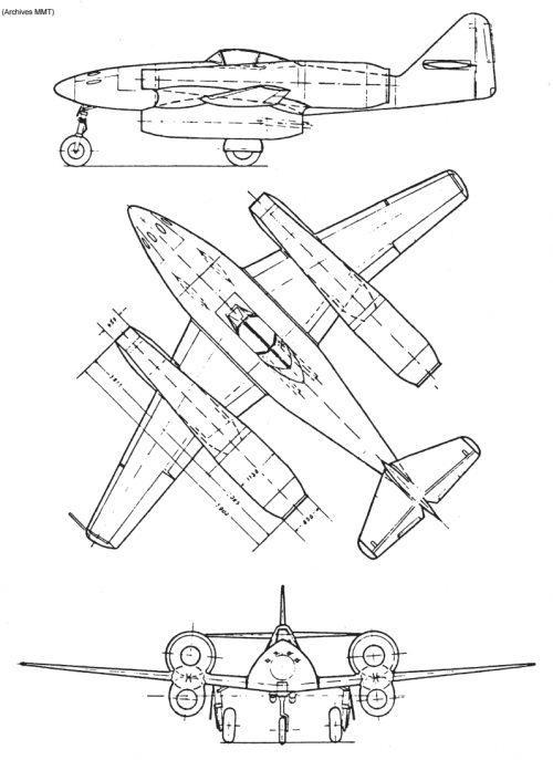
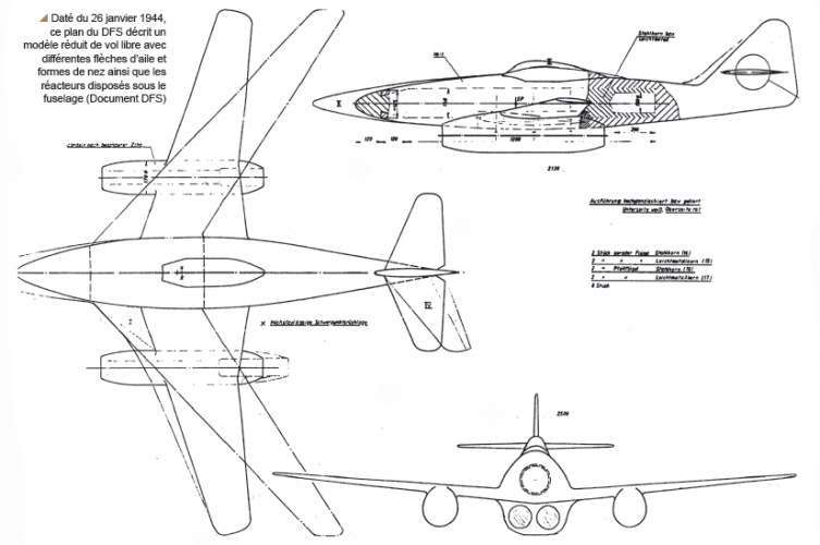
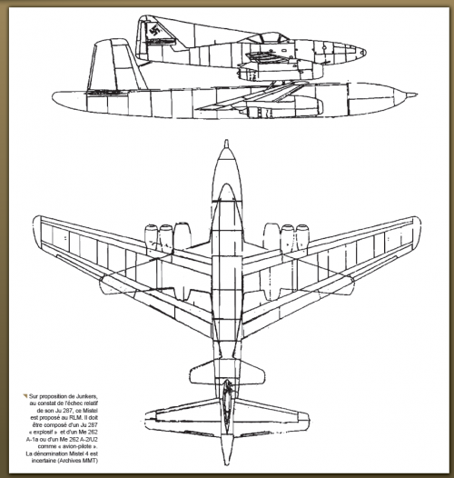
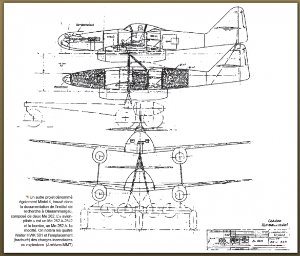
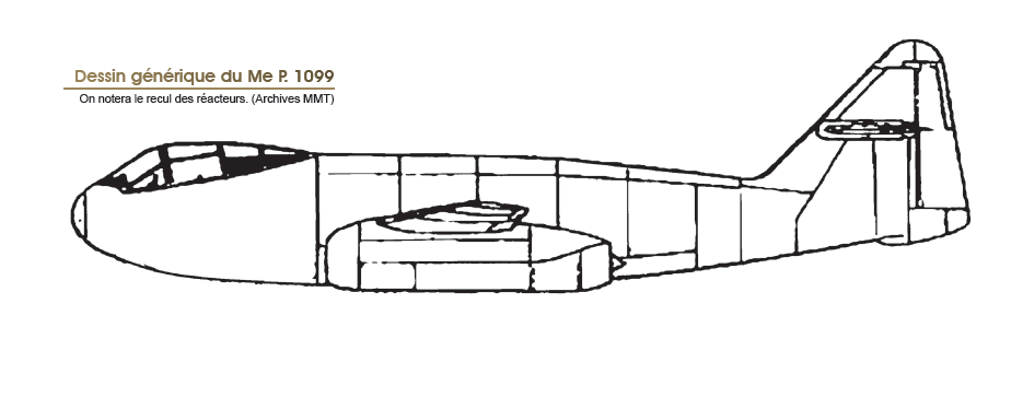
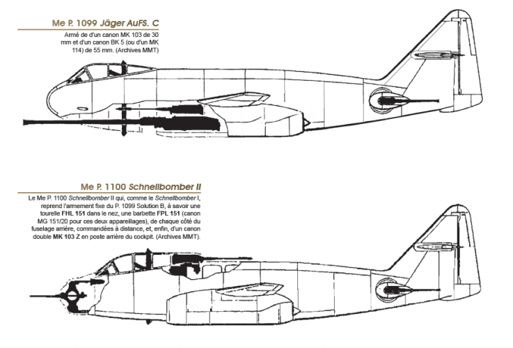
From this source.
Attachments
-
 1.png358.4 KB · Views: 36
 -
 2.png129.4 KB · Views: 35
 -
 3.png146.3 KB · Views: 37
 -
 4.png516.1 KB · Views: 42
 -
 5.png199.1 KB · Views: 43
 -
 6.png214.1 KB · Views: 43
 -
 7.png135.3 KB · Views: 42
 -
 8.png57.8 KB · Views: 42
 -
 9.png181.3 KB · Views: 37
 -
 10.png119.1 KB · Views: 38
 -
 11.png164.8 KB · Views: 41
 -
 12.png313.7 KB · Views: 44
 -
 13.png362.6 KB · Views: 46
 -
 14.png181.4 KB · Views: 44
 -
 15.png109.1 KB · Views: 43
 -
 16.png122.1 KB · Views: 44
 -
 17.png144.9 KB · Views: 46
 -
 18.png36.3 KB · Views: 47
 -
 19.png92 KB · Views: 50
 -
 20.png485.5 KB · Views: 70

- Joined
- 19 July 2016
- Messages
- 4,816
- Reaction score
- 4,276
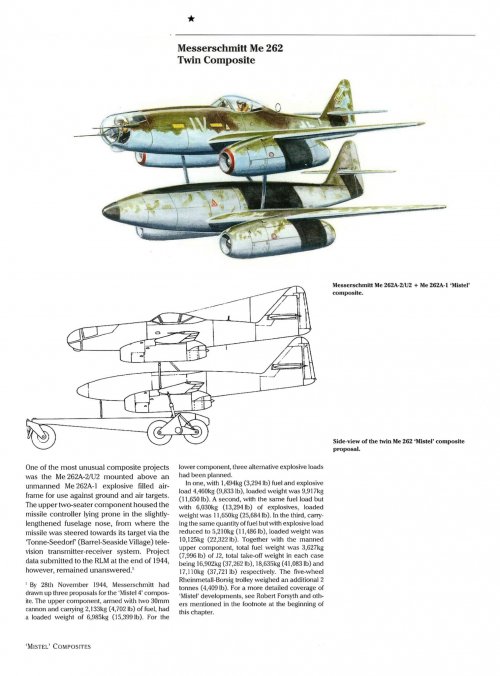
Another tangent, sorry folks. Minus the Jumo nacelles, what would the performance have been like with a properly sorted engine mounted in the nose? Talking about V1.

- Joined
- 19 July 2016
- Messages
- 4,816
- Reaction score
- 4,276
Pardon me, Looking for the best available rather than the engine used in testing and minus the nacelles.
Similar threads
-
 Messerschmitt Me 262 Development & Politics by Dan Sharp
- Started by Dan Sharp
- Replies: 153
-
-

-
German high-powered piston engined fighters
- Started by Wurger
- Replies: 23
-
Focke Wulf Fw 190 / Ta 152 Projects & Variants
- Started by Justo Miranda
- Replies: 552