Fair point.

It's still ugly to me. The original Pegasus lift is so much more elegant.
I agree, it's so simple compared with other approaches to the problem of direct lift. We found as a practical matter, though, that if you have everything in the airplane competing for space close to the c.g. (engine, wing, fuel) you end up with a fat midsection and impossible transonic drag rise characteristics. I think I mentioned somewhere that we arbitrarily froze the -408 Pegasus engine's size but doubled and tripled its thrust with nozzles aft, and couldn't get past Mach 1. To reach our Harrier 21's defined dash speed we had to decouple something from that midsection, and it turned out to be the Pegasus, its core at least, in its new wrapper. So in hover we still had the well-proven Pegasus direct lift concept, but in a 3-poster instead of a 4-poster.
Strange side story: I vividly remember that there was a large wood wind tunnel model left over when the program was shut down. I even remember whose desk it hung over for years. But it disappeared, and I was told that there never had been such a model. I'm also sure there was a wind tunnel model for MiniCAS, too, although I don't remember ever actually seeing that one; I know it existed because a program manager once told me it had cost $40,000. It's amazing how much stuff just disappears... :)
 
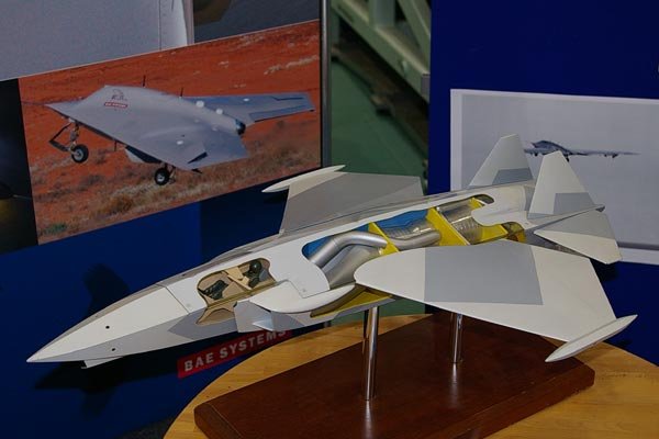
Is this a real McDonnell Dougals ASTOVL design ?,they said;


McDonnell Douglas - REN cactus project - lift plus lift/cruise (LLC)

http://www.airborn12.com/extras/fighters.html

Steve
I very briefly (just before leaving RR) worked on an engine dec for a pancake GCLF architecture, two fan stages driven by tip turbines (no connection shaft) at half the thrust of our main cylindrical offering. I assumed it was for packaging within strakes so was duplicated port and starboard. The small outer diameter worked a little better with matching the rotor dynamics. We rarely or never got to see the aircraft configuration. Not sure if this was in response to a MDC or BAe request/proposal. Do you remember any such scheme?
Does hesham’s post match your description?
 

Attachments

  • ASTOVL.jpg
    ASTOVL.jpg
    11.8 KB · Views: 610
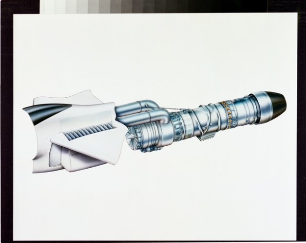
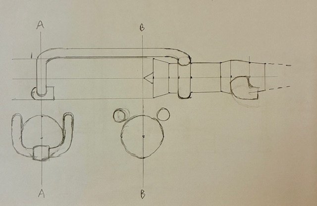
Had another go at the Harrier 21 engine layout. Please excuse the crude method used, I couldn’t find my crayons ;)

Basically the front nozzles on the Pegasus are replaced by two ducts feeding a single central nozzle with left and right flows kept separate by a centre divider.

The layout of the rear nozzles could possibly match the layouts of the McDD/NGC/BAe JAST and JSF proposals.

I assume the engine would be behind the undercarriage to allow drop out maintenance so the ducts could be mounted higher on the fan casing. Forgot what thread the nice engine image is from. Will edit later. https://www.secretprojects.co.uk/th...-mcdonnell-bae-astovl-entry.2219/#post-716905
 

Attachments

  • IMG_3872.jpeg
    IMG_3872.jpeg
    55.1 KB · Views: 401
  • IMG_3867.jpeg
    IMG_3867.jpeg
    172.2 KB · Views: 350
  • IMG_0335.jpeg
    IMG_0335.jpeg
    228 KB · Views: 342
Last edited:
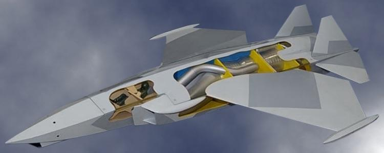
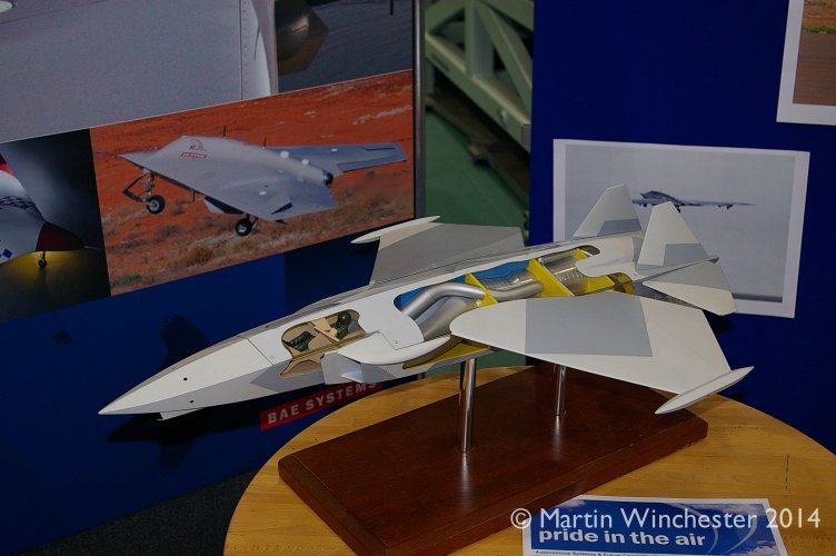
In another thread I mentioned that my group at McDonnell Douglas had come up with a supersonic STOVL fighter/attack airplane that we called Harrier 21. It was supposed to be one of a series of potential AV-8B follow-ons. There was Harrier III Low End, a modest modification of the basic AV-8B with limited gains in performance, and Harrier III Medium which was about as far as the basic airframe could be expanded. Both were subsonic because of the drastic transonic drag rise associated with the Harrier's fundamental layout. Harrier 21 was originally called Harrier III High End but since it was a completely new aircraft, that designation really didn't fit, hence Harrier 21, a new member of the Harrier family for the 21st Century.

I've written at length in other Harrier variant posts about the process of creating the configuration, so I won't repeat that here. But I didn't reveal any images other than one front view that had been posted by someone else in a batch of Harrier line drawings. I can't see any harm in posting this picture though, it doesn't reveal any technical details, just the general shape of the aircraft. I painted it at the time, 1991, and I'm not sure that it even represents the final configuration, but it's what was being looked at during my involvement. I'm no artist, and the painting is rather crude, I didn't even bother to prime the canvas board to get rid of the cloth texture and give a smooth surface. Still, I hope this will be of interest to anyone who's interested in "never-never" Harrier derivatives, or what might have been if only ASTOVL hadn't shut us down. :)

View attachment 774189
You certainly are an artist...nice work here
 
Had another go at the Harrier 21 engine layout. Please excuse the crude method used, I couldn’t find my crayons ;)

Basically the front nozzles on the Pegasus are replaced by two ducts feeding a single central nozzle with left and right flows kept separate by a centre divider.

The layout of the rear nozzles could possibly match the layouts of the McDD/NGC/BAe JAST and JSF proposals.

I assume the engine would be behind the undercarriage to allow drop out maintenance so the ducts could be mounted higher on the fan casing. Forgot what thread the nice engine image is from. Will edit later.
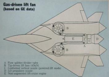
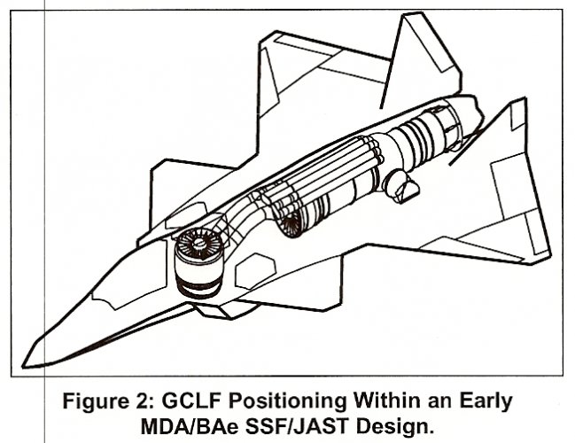
That GCLF drawing nearly gave me PTSD flashbacks. :) Our shops built an "iron bird" mockup of that thing, only partly skinned as I recall, and after the program went away it sat uncovered outside our building in the weather for years. It finally got sent to scrap. I worked in that building for a long time, and every time I'd walk by that derelict thing it would remind me of what a raw deal we'd gotten in the whole ASTOVL mess. Normally I'm a fanatic for preserving rare aviation artifacts but I wasn't sorry when this particular one disappeared.
 
What were the theoretical benefits the GCLF was supposed to have? I'm having difficulty seeing any. All of the risk of the SDLF but more weight, more volume, and concerns about battle damage noted in the past. Was it funded as a matter of "maybe SDLF won't work and this will"?
 
Steve
I very briefly (just before leaving RR) worked on an engine dec for a pancake GCLF architecture, two fan stages driven by tip turbines (no connection shaft) at half the thrust of our main cylindrical offering. I assumed it was for packaging within strakes so was duplicated port and starboard. The small outer diameter worked a little better with matching the rotor dynamics. We rarely or never got to see the aircraft configuration. Not sure if this was in response to a MDC or BAe request/proposal. Do you remember any such scheme?
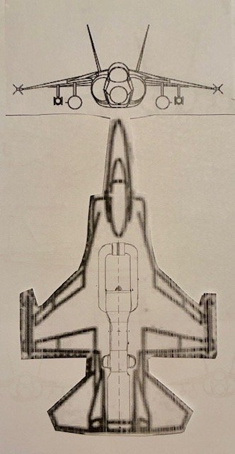
I don't remember the propulsion system details, I'm afraid. I thought I had a 3-view with inboard profile around here somewhere but I can't seem to find it. Maybe in storage, I'll try to remember to look for it the next time I'm down there. There may have been patents on the GCLF integration part of the design that could provide more insight.
 
What were the theoretical benefits the GCLF was supposed to have? I'm having difficulty seeing any. All of the risk of the SDLF but more weight, more volume, and concerns about battle damage noted in the past. Was it funded as a matter of "maybe SDLF won't work and this will"?
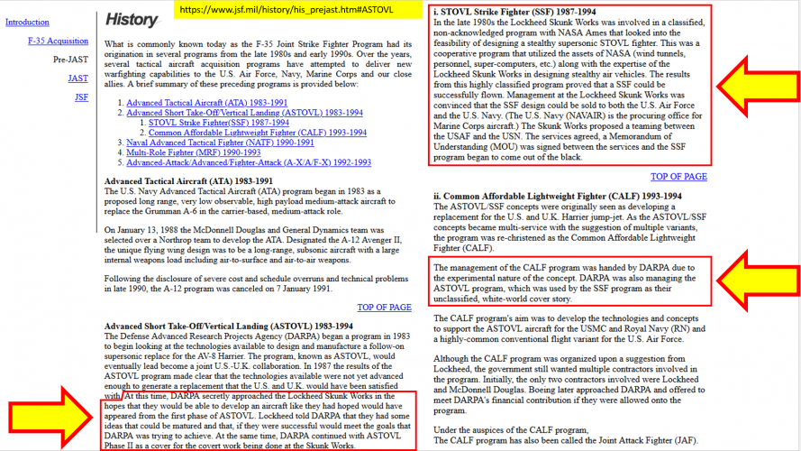
There weren't any benefits beyond a vague feeling that it was mechanically simpler, without gearboxes and a drive shaft. But the high-pressure air ducts were huge and they ate up interior volume where fuel tanks and electrical wiring and hydraulic lines should have gone, so we had to make the fuselage itself fatter to accommodate what we couldn't eliminate, making the airplane heavier and more expensive. All the benefits were on the SDLF side. DARPA knew it, we knew it, everybody knew it. They and others secretly funded Lockheed to develop what became the shaf-driven LiftFan and used programs like ours as a white-world cover for that work, rigging the JAST/JSF competition heavily in Lockheed's favor and, as it turned out, ultimately contributing to the failure of MDA and the McDonnell Douglas corporate merger with Boeing.

For many years JSF carried the full backstory on the program's "jsf.mil" website. Wayback Machine still has those pages but I can't find my link right now, so here are copies of the pages that I took and annotated directly from that original Government source.

1765921562266.png
 
Last edited:
Do any photos for it exist?
They would have existed at the time, in the Company photo archive, but I don't know whether they've survived. I'll get in touch with the local Historian's office and see what they have, but even if they exist, Boeing doesn't do "personal license" so a full-blown commercial release-style license would have to be purchased before they'd let go of the images. They have a few XP-67 photos that I didn't already have, but they wouldn't let me have copies without paying for a license that had unusually intrusive and restrictive terms, so I passed on them. But I'll check and see.
 
Do any photos for it exist?
It took awhile to get a reply from the Boeing Historian due to the holidays, but the answer was no, they don't have any photos of the GCLF version ASTOVL mockup. I feel like there were probably photos in some of the aviation magazines of the day but those are either gone or hidden behind paywalls. Even NASA has gutted their online historical image presence.
 
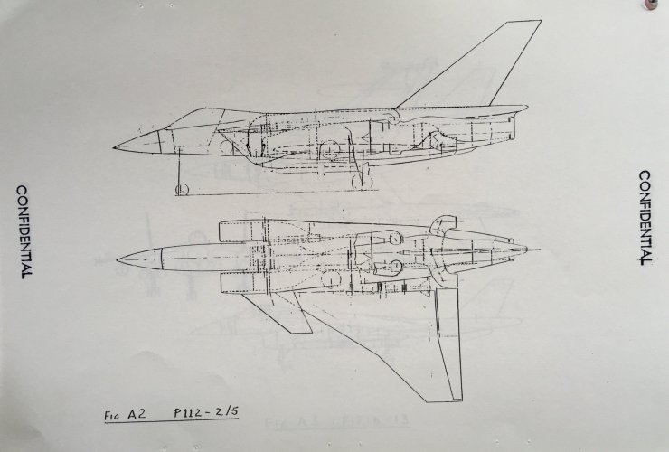
Nice picture of the BAe P112 ASTOVL project showing the engine installation which I think will be similar to the Harrier 21 when finally revealed.

Comparing it to the partial side view stever_sl shared, I think you can just make out the bottom of the fan casing at the top of the door behind the main undercarriage.
 

Attachments

  • IMG_0349.jpeg
    IMG_0349.jpeg
    257.5 KB · Views: 361
  • 1755010574645.png
    1755010574645.png
    351.8 KB · Views: 307
I refined my ideas of how the lift system on the Harrier 21 might look based on the P112 layout. If I remember correctly the P112 had burning in the front nozzle called RALS - Remote Augmented Lift System. The stealthy P125 had a non burning system called RULS - Remote Unaugmented Lift System. My take on RULS ends with a single Harrier style rotating nozzle fed from ducting on both sides. A splitter plate keeps the flows separate. The engine will obviously have valves/clang boxes to divert the flows to the lift nozzles as required.
The intake and ductwork are straight lines for ease of illustration.
 

Attachments

  • IMG_0015.jpeg
    IMG_0015.jpeg
    40.8 KB · Views: 318
  • IMG_3961.jpeg
    IMG_3961.jpeg
    78.7 KB · Views: 303
  • IMG_3960.jpeg
    IMG_3960.jpeg
    89.7 KB · Views: 320
Last edited:
If you mean during the first-round JAST downselect, when MDA was teamed with BAe and Northrop, there was good reason to fear what St Louis could do, technically. But that team never found its footing. Work split between the companies was a big problem. For reasons I will never understand, selecting the STOVL variant's vertical lift propulsion method was allocated to Northrop, who had never done a production VTOL anything, rather than either of the 2 other team companies which between them had 100% of the actual US/UK VTOL production experience. That doomed our JAST proposal. The configuration itself was a lovely thing (in my eyes) but its lift engine made it impossible for the Marines to accept it, no matter how much more efficient Northrop insisted it was than other solutions. Boeing's dark-horse win in that competition came out of nowhere and their design was, to put it bluntly, silly.

If you mean the final JSF downselect, St Louis wasn't in the driver's seat at all, Puget Sound was. We (St Louis) wasted months trying to get them to understand that their tailless thing might be OK for the land-based variant and maybe even for the STOVL variant but not for the naval variant. Without going over that ground again, I'll just say that there are significant issues with having all of your pitch and roll and high-lift controls concentrated on one trailing edge, when it comes to landing aboard a ship at night in rough weather. St Louis had decades of experience with shipboard fighter/attack, Seattle had none, but what we kept being told was "if you're so smart, why did you lose JAST? Why did we get to buy you instead of the other way around?" It didn't help that the tailless configuration was patented by PS people, including one who would in later years go on to become Boeing's CEO, putting much pressure on keeping the X-32 design within the patent's protective parameters. St Louis's experience with shipboard operations, STOVL technologies, and in fact tactical jet fighter/attack knowledge (and how to deal with a Government customer rather than commercial ones) were all just held in low regard by PS management, at least that's how it seemed to us. Remember that the last Boeing fighter that made it into production was the P-26 of 1932, while we had multiple production lines running for all 3 US Services and many foreign customers as well. It was frustrating, and in the end fatal to our ability to develop a winnable design.
Having worked on other programs at Northrop during that period (B-2A, TSSAM), I can't say I'm totally surprised. Upper management at that time was somewhat suspect to the "worker bees". IMHO, T. V. Jones stayed too long and Kent Kresa wasn't an ideal replacement.
 
I refined my ideas of how the lift system on the Harrier 21 might look based on the P112 layout. If I remember correctly the P112 had burning in the front nozzle called RALS - Remote Augmented Lift System. The stealthy P125 had a non burning system called RULS - Remote Unaugmented Lift System. My take on RULS ends with a single Harrier style rotating nozzle fed from ducting on both sides. A splitter plate keeps the flows separate. The engine will obviously have valves/clang boxes to divert the flows to the lift nozzles as required.
The intake and ductwork are straight lines for ease of illustration.
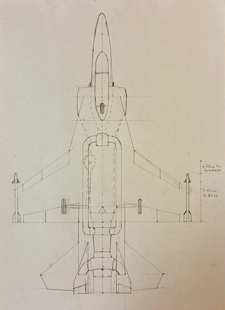
I'd give the top view airframe outline 9 out of 10, in fact I was startled when I saw it until I remembered that I'd posted my rough painting of the airplane awhile back. And the propulsion layout is correct in general concept, but the overall integration of the CTOL and VTOL specific equipment is different enough to be a problem. Think about what mechanism there would have to be in order to switch back and forth between those thrust modes, and where it would have to be located, and what that would do to the engine's location in the airframe. :)
 
Thanks for the feedback stever_sl :)

The top view actually came from matching up your Harrier evolution chart and partial side and top views. I wouldn’t call your painting “rough” either!

The engine came from the P112 picture and I used the AMRAAM and Sidewinder lengths to roughly scale it to the Harrier 21 fuselage. Putting the engine behind the main undercarriage allows for drop out maintenance but gave it a shorter conventional cruise flight nozzle than I hoped for.

I’ve got some ideas about the transition mechanisms required but it really does make you appreciate the genius of the simpler Pegasus four poster solution!
 
More info on the Harrier 21 engines -
Oh, but you were so close last August!

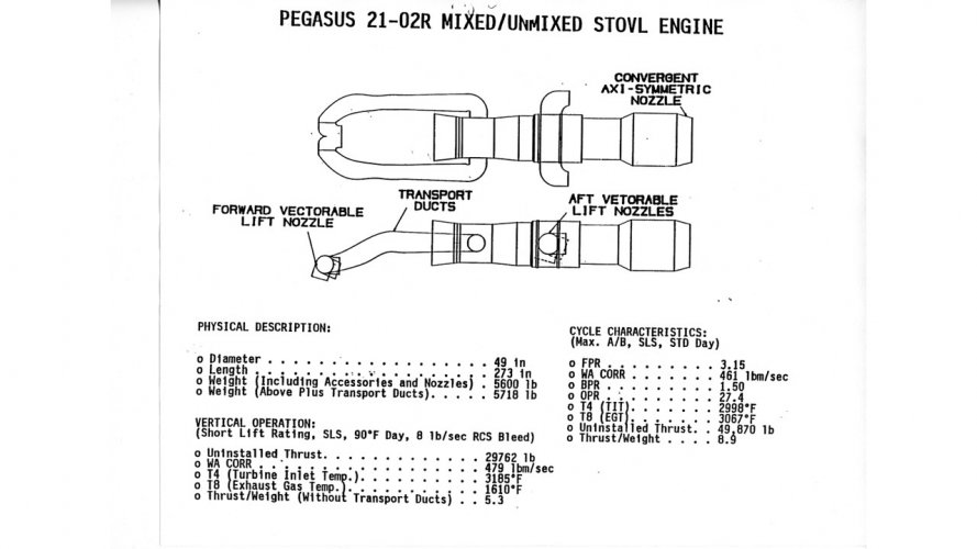
I was really surprised to learn that the Rolls Royce Heritage Trust had no details on the RB.578 (Pegasus core) or RB.571 (EJ200 core.) So this morning I dug out the MCAIR H21 data package and had a closer look, and the engine page for the Pegasus version calls it "Pegasus 21-02R Mixed/Unmixed STOVL Engine." where "R" means "reheat" as usual. I'm going to see if the RR Heritage Trust has anything under that designation. It also calls the other one "RB-571-13" so I'll check that as well. And I've often wondered why the prototype demonstrator's Pegasus-based engine would have a later number (578) than the production version would have had (571) and today it occurred to me that RR might well have been working on the 571 for some other project before joining us on H21. In that case they would have been adapting that concept backward to the Pegasus core, which would explain the numbering oddity.

View attachment 813776

Got a source - For RB571 anyway, and RB578 was the same functionally but with the Pegasus core. This is for a different BAe study aircraft but it should be everything you need to understand the same engine in H21. It's not obvious at first glance what's going on inside the engine "assembly" (core plus case plus flow control valve) so I added some red boxes to highlight the differences between the Lift and Flight mode configurations. Honestly it's still not the best illustration but it's all I could find. Just know that there was a block-and-turn valve mechanism that let part of the "cold" (pre-combustion) flow go forward and "hot" exhaust go to Harrier-style swiveling nozzles for Lift mode, and closed those paths off (and retracted the nozzles) for Flight mode. I distinctly recall the chief RR guy visiting with a model of that mechanism, and being amazed at how simple it was, mechanically.
Link to entire paper: https://apps.dtic.mil/sti/tr/pdf/ADP011121.pdf

View attachment 813786
 
In the early 1990s McDonnell Douglas's Advanced AV-8 and V/STOL group was working with British Aerospace and Rolls Royce on potential growth variants of AV-8B with an eye to future production when that aircraft's contracts were all completed. I was in a small Operations Analysis team within that group and I lobbied for a supersonic clean-sheet design because the prime customer for any future STOVL machine, the USMC, was committed to a program of reducing the number of different types of aircraft it operated in order to streamline maintenance and spares stocking, and had said many times that they would love to have what they called a "Hovering Hornet" to replace both their F/A-18s and AV-8Bs. Although there was a very strong bias within our group to just grow the Harrier itself, that would mean settling for a subsonic aircraft, which seemed to me to be a nonstarter. (ASTOVL had the alternative supersonic future in hand, but we had seen many such high-profile programs disappear or get consolidated with other programs in the past, so in a sense a supersonic Harrier replacement study might be a good backup to have in hand.) Most of our group members seemed happy to stay subsonic within our "Harrier III" charter, and I think I caused a lot of irritation by continually bringing up the supersonic question. Finally the head of our Aero group did some analyses to show me that the basic supercritical wing couldn't be made to get through the transonic drag rise even if you arbitrarily doubled or tripled the amount of thrust available to push it. So a new wing would be needed, and somehow that seemed to make a psychological difference to key people and a study was launched to see what might be accomplished along those lines.

The main thing we needed was a way to incorporate afterburning in the engine. Plenum chamber burning seemed like a dead end. Rolls Royce, however, came up with a radical new repackaging of the Pegasus engine core that put the hot exhaust in the tail where it belonged, and a conventional afterburner was suddenly possible. With that, we actually had a viable airplane. It got the designation "Harrier III High End" since it was the highest-performance variant in the Harrier III lineup, which also featured (naturally) a Low End minimal change lowest-cost variant and a Medium that took the basic Harrier about as far as it could go. I think those have been documented elsewhere.

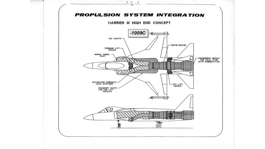
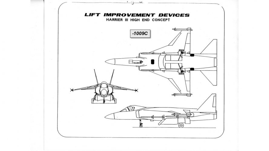
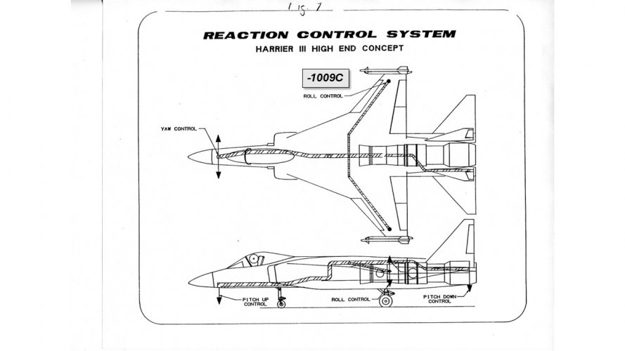
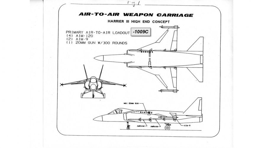
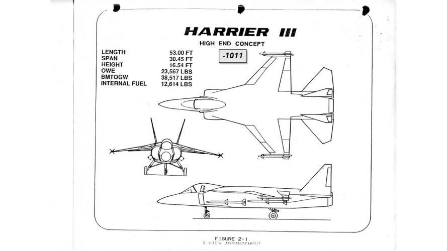
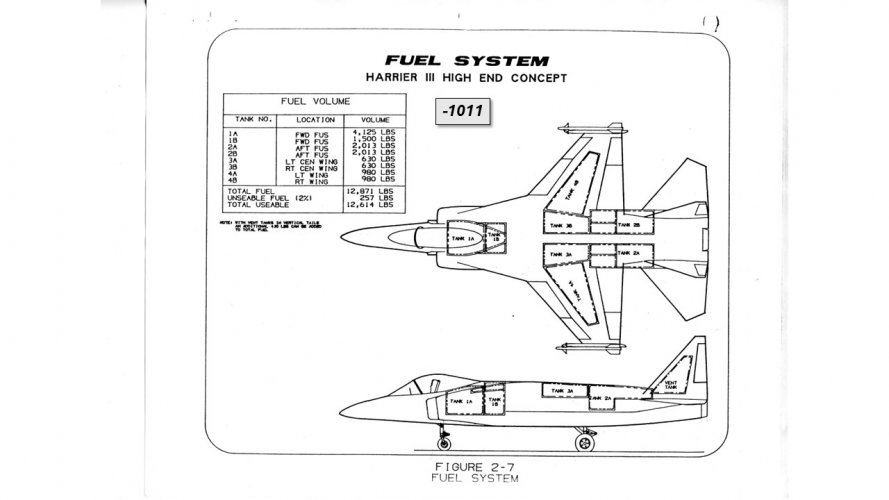
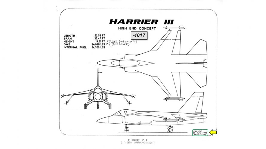
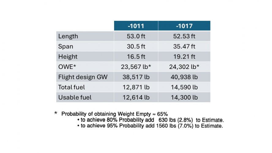
We took an unusual approach to generating a configuration for H21 by defining a set of performance requirements and having the St Louis and UK teams each design something to meet those requirements using the same RR engine. The idea was that we'd see what good ideas could be extracted from each configuration and combined into a joint product. Strange, but it actually worked well. The only information that remains about the MCAIR configuration involves 3 iterations called H3H-1009C and its next refinement, H3H-1011, and a final one called H3H-1017. The BAe specific configurations haven't been found, but the -1017 is said in its Configuration Description document to have adopted a number of its features: “The H3H-1017 is derived from the H3H-1011 in order to move closer to a merged high end concept for Harrier III between British Aerospace and McAir. The major differences between the -1011 and -1017 are bigger wing with fold, single larger vertical tail with fold, different inlet shape, different RCS [reaction control system, for vertical flight] and slightly shorter fuselage.”

Four sketches of -1009C features still exist, two of -1011 features, one of the -1017, and one of the repackaged Pegasus engine that would power any H21 prototype. These are attached along with a table of the basic characteristics of the aircraft. It's a little difficult to confirm the "slightly shorter fuselage" comment in particular via these sketches; it looks to be quite a bit shorter, much more so than the data table would indicate. But after all this is a collection of fragmentary surviving documents from more than 30 years ago, so we should be happy just to have them at all.

A technical note: The only potentially revolutionary technology in the whole airplane was the engine and STOVL control integration. Since it has already been published as a part of the ASTOVL aircraft documentation, there should be no residual sensitivity now, especially since it proved to be a dead end due to skulduggery behind the entire ASTOVL/JAST/JSF program involving covert funding to develop LiftFan technologies instead. That subject has been covered elsewhere too. Our team awoke strong interest from the Royal Navy, who offered (according to RR) 2 billion pounds to support our effort if we included certain performance points in our requirements, which we were obviously happy to do. And the one and only briefing we ever gave to some Marine pilots produced overwhelming enthusiasm as well. But as I've recounted elsewhere, our effort was shut down when the MCAIR ASTOVL group heard what we were doing, so I believe that the -1017 configuration might have been the last iteration of H21. I can't be sure, because our chief designer has moved on and I haven't been able to reach him. If anyone has contacts at BAe or RR who might be able to shed more light on this, I'd love to hear about it.
 

Attachments

  • Slide1.JPG
    Slide1.JPG
    107.2 KB · Views: 273
  • Slide2.JPG
    Slide2.JPG
    121.6 KB · Views: 267
  • Slide4.JPG
    Slide4.JPG
    87.7 KB · Views: 257
  • Slide3.JPG
    Slide3.JPG
    100.3 KB · Views: 260
  • Slide5.JPG
    Slide5.JPG
    99.4 KB · Views: 264
  • Slide6.JPG
    Slide6.JPG
    94.7 KB · Views: 270
  • Slide7.JPG
    Slide7.JPG
    104.8 KB · Views: 261
  • Slide8.JPG
    Slide8.JPG
    89.9 KB · Views: 261
  • Slide9.JPG
    Slide9.JPG
    96.9 KB · Views: 254
Last edited:
Did the name 'Rob Rowe' appear ??

Happens I met him 'later', as his wife bred & judged super-sassy Siamese cats.
Bound by enduring NDA, he would only say that PCB was a dead end, but they'd figured a better way. Then politics killed the project...
 
The propulsion system is essentially that of the BAe P125 - 'RULS - Remote Unaugmented Lift System' from 1988.

The 1990 International Powered Lift Conference Proceedings has an article by Sandy Mitchell that described the engine, and there is an article in a copy of Flight International from 1989 (sorry, lost ref when their online archive went).

Judging by the turbine temp the engine of this Harrier III (the UK had their own aircraft designs called that) is the version with the F119 core.

I'm not surprised the RN were interested. They were trying to get BAe to push their own clean sheet design for shipboard use, the P.145, in the early 90s.

1785958620274.png '
 
Last edited:
The propulsion system is essentially that of the BAe P125 - 'RULS - Remote Unaugmented Lift System' from 1988.

The 1990 International Powered Lift Conference Proceedings has an article by Sandy Mitchell that described the engine, and there is an article in a copy of Flight International from 1989 (sorry, lost ref when their online archive went).

Judging by the turbine temp the engine of this Harrier III (the UK had their own aircraft designs called that) is the version with the F119 core.

I'm not surprised the RN were interested. They were trying to get BAe to push their own clean sheet design for shipboard use, the P.145, in the early 90s.

View attachment 820101'
The core was actually - well, let me start over. There were 2 versions of the engine. The first used the Pegasus core, which my memory tells me was for the prototypes only, and then if the project was successful, the production aircraft would replace that core with the one from Eurofighter, which I think at the time was RB199. Thinking about it today, though, it seems odd that the mission performance would have been done in such detail on just the Pegasus-core basis, and yet that's all that appears in the requirements tables and performance calculations for the -1011 and -1017 configurations. I can't remember seeing any other engines in any performance calculations, but then again it was a long time ago and I haven't been able to find anyone else who saved any of the data, for cross-checking, so I could be wrong.
 
Did the name 'Rob Rowe' appear ??

Happens I met him 'later', as his wife bred & judged super-sassy Siamese cats.
Bound by enduring NDA, he would only say that PCB was a dead end, but they'd figured a better way. Then politics killed the project...
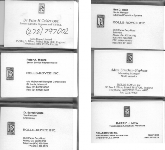
The name rings a vague bell but it's always possible that I'm confusing it with the actor Rob Lowe or something. I never met with any of the BAe folks as far as I can recall. I only met RR people because they came to St Louis occasionally to coordinate with our technical guys. I was very disappointed when the head of the Rolls Royce Heritage Trust said that he was unable to find anything about this effort in their extensive archives, apart from the fact that the designations "RB.578" (initial prototypes) and "RB.571" (production aircraft) are in their list of engines, with nothing more than the most basic notes. I'll attach the RR folks' business cards, maybe someone will be able to chip in with more information.
1785963098920.png
 
The core was actually - well, let me start over. There were 2 versions of the engine. The first used the Pegasus core, which my memory tells me was for the prototypes only, and then if the project was successful, the production aircraft would replace that core with the one from Eurofighter, which I think at the time was RB199. Thinking about it today, though, it seems odd that the mission performance would have been done in such detail on just the Pegasus-core basis, and yet that's all that appears in the requirements tables and performance calculations for the -1011 and -1017 configurations. I can't remember seeing any other engines in any performance calculations, but then again it was a long time ago and I haven't been able to find anyone else who saved any of the data, for cross-checking, so I could be wrong.
I just went back and looked again at the entire data package, and for both -1011 and -1017 the specified engine is the RB 571-13. So that does make sense after all. We must have planned to generate a production-relevant configuration, then back out a simplified proof-of-concept demonstrator, and only those initial demonstrators would have had the RB 578.
 
A few top-level details:

Design Mach # was 1.8.

Max Mach # in afterburner was from 0.91-1.5 depending on altitude and stores load-out. Some of those performance points seem odd, like using full afterburner for the air-to-ground loading cases, but that's what was in the data package and I'm sure there were reasons for it at the time.

Missions for which performance goals were defined were Combat Air Patrol, Deck Launched Intercept, Fighter Escort, Close Air Support, Interdiction, and Antiship. You can probably see the big difference between this list and what USMC Harriers were mainly doing; that's the strong influence of the Royal Navy with its promised funding support.
 
Great topic everyone. On the engines, from the forum
RB.578 - (Project) Pegasus 11-61 devel., 25,300 lbf dry
- RB.578: Stowable lift nozzles and rear afterburner
- RB.578: Related to RB.571 but retaining Pegasus core
-- 27,000 lbf in lift mode, 41,300 lbf in reheat
-- https://www.secretprojects.co.uk/threads/advanced-harrier-projects.184/page-6#post-700829

RB.571 - (Project) Hybrid turbofan for US/UK ASTOVL use
- RB.571: Lift nozzle + vectored thrust + conv. afterburner
- RB.571: Related to RB.578 but using Eurojet EJ200 core
-- Intended for naval variant of Eurofighter EFA/EF 2000
-- https://www.flightglobal.com/FlightPDFArchive/1989/1989 - 2869.PDF
-- https://www.secretprojects.co.uk/threads/advanced-harrier-projects.184/page-6#post-70082
https://www.secretprojects.co.uk/threads/rolls-royce-rb-designations.27741/
 

Attachments

  • IMG_4240.jpeg
    IMG_4240.jpeg
    26.8 KB · Views: 98
  • IMG_4241.jpeg
    IMG_4241.jpeg
    26.2 KB · Views: 138
Thanks so much for sharing the Harrier 21 story stever_sl

I nearly guessed it right in the previous threads! Now I have to work out how the engine blockers work :)

https://www.secretprojects.co.uk/threads/mcdonnell-douglas-harrier-iii-high-end-harrier-21.46703/

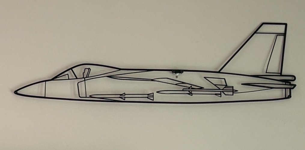
https://www.secretprojects.co.uk/threads/harrier-21-and-minicas-hanging-on-my-wall-now.51750/
I'm afraid I have no idea exactly how that was mechanized. Dr Calder brought a model to one meeting and twisted it somehow to illustrate how it would work, and I think he called it a "block and turn valve." In the drawings I provided earlier, that would be the big cylindrical section between the aft vectorable nozzles and the main centerline axisymmetric conventional flight nozzle. Maybe the ASTOVL information would have more info, particularly that AIAA (or was it NASA?) report on testing of the RB571-10 propulsion system. My only link to it was for DTIC, and they seem to be perpetually "down for maintenance" these days. ( https://apps.dtic.mil/sti/tr/pdf/ADP011121.pdf ) Here's all that I have from it:
 

Attachments

  • 1785983890954.png
    1785983890954.png
    724.6 KB · Views: 186
Last edited by a moderator:
In the early 1990s McDonnell Douglas's Advanced AV-8 and V/STOL group was working with British Aerospace and Rolls Royce on potential growth variants of AV-8B with an eye to future production when that aircraft's contracts were all completed.
Have there been research into how much loss the transport ducts would have added to the system in vertical mode? Vertical mode thrust already looks relatively tight compared to OEW, and if a further few hundred or even thousand pounds were to get shaved off due to losses the capabilities in vtol mode would seem to be... suboptimal, for lack of a better word.
 
Last edited by a moderator:
I'm afraid I have no idea exactly how that was mechanized. Dr Calder brought a model to one meeting and twisted it somehow to illustrate how it would work, and I think he called it a "block and turn valve." In the drawings I provided earlier, that would be the big cylindrical section between the aft vectorable nozzles and the main centerline axisymmetric conventional flight nozzle. Maybe the ASTOVL information would have more info, particularly that AIAA (or was it NASA?) report on testing of the RB571-10 propulsion system. My only link to it was for DTIC, and they seem to be perpetually "down for maintenance" these days. ( https://apps.dtic.mil/sti/tr/pdf/ADP011121.pdf ) Here's all that I have from it:
Tada
http://web.archive.org/web/20250202082505/https://apps.dtic.mil/sti/tr/pdf/ADP011121.pdf
 
Last edited:
I'm afraid I have no idea exactly how that was mechanized. Dr Calder brought a model to one meeting and twisted it somehow to illustrate how it would work, and I think he called it a "block and turn valve." In the drawings I provided earlier, that would be the big cylindrical section between the aft vectorable nozzles and the main centerline axisymmetric conventional flight nozzle. Maybe the ASTOVL information would have more info, particularly that AIAA (or was it NASA?) report on testing of the RB571-10 propulsion system. My only link to it was for DTIC, and they seem to be perpetually "down for maintenance" these days. ( https://apps.dtic.mil/sti/tr/pdf/ADP011121.pdf ) Here's all that I have from it:
Yes, a ”block and turn valve” or maybe a “turn to block valve” sounds like what I have been thinking of.

I think a variable stator ring where each blade can twist enough to fully block the flow with its neighbouring blades might work.

Another idea is to a split the stators into two rings. The front ring has the leading edge and the back ring has the trailing edge of the stator. When one or both rings rotate the stator splits in the middle to block the flow.

Probably easier to do for front nozzles than the back!

Maybe the side openings for the lift nozzles could be incorporated into this “turn to block” mechanism as a louvre vent like valve?
 
Have there been research into how much loss the transport ducts would have added to the system in vertical mode? Vertical mode thrust already looks relatively tight compared to OEW, and if a further few hundred or even thousand pounds were to get shaved off due to losses the capabilities in vtol mode would seem to be... suboptimal, for lack of a better word.
Oh yes, that was a big concern at the time and a lot of effort was spent on getting that part right. RR took the lead on that, and given the caliber of people they put onto this project, I have every confidence that their numbers were conservative, if anything.
 
Yes, a ”block and turn valve” or maybe a “turn to block valve” sounds like what I have been thinking of.

I think a variable stator ring where each blade can twist enough to fully block the flow with its neighbouring blades might work.

Another idea is to a split the stators into two rings. The front ring has the leading edge and the back ring has the trailing edge of the stator. When one or both rings rotate the stator splits in the middle to block the flow.

Probably easier to do for front nozzles than the back!

Maybe the side openings for the lift nozzles could be incorporated into this “turn to block” mechanism as a louvre vent like valve?
If you look closely at the modes drawing I posted, I added some red highlights to show what was going on to "things" inside the shell. Switch modes appears to have been a matter of sliding rings of some sort backward and forward. Exactly what they looked like, or what they were blocking off and opening up, I don't know. But those are the only things that appear to change in the mode illustrations.

Surely somebody, somewhere, has more on this!
 
Fantastic view ! Thank you !

Did you ever speak about the Harrier III Medium on another thread ?
It's cropped up in other people's posts, like this: https://www.secretprojects.co.uk/threads/advanced-harrier-projects.184/

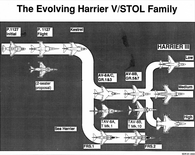
And I posted this somewhere, showing how it and the H21 fit into the overall Harrier family tree. It looks crude because it was made in the days when "cut and paste" meant literally that, cutting out tiny little paper bits and gluing them onto a background piece of paper. And the shading was done using a long-vanished (I expect) product that had itty bitty dots printed on adhesive-backed mylar, that you cut to shape and stuck down onto that background paper before sticking the airplane bits to it. And at the end of the day we climbed onto the backs of our dinosaurs and lumbered back home to our caves... :) Looking at this illustration now, the Harrier III High End seems to be the -1011. It has the twin vertical tails of the -1009 but the clipped horizontal tails that would carry through into the next iteration, -1017 which would have picked up the single vertical tail from the BAe-developed configuration.
1786023199504.png
 
Oh yes, that was a big concern at the time and a lot of effort was spent on getting that part right. RR took the lead on that, and given the caliber of people they put onto this project, I have every confidence that their numbers were conservative, if anything.
thanks for the reply! I was originally thinking along the lines of XFV-12 with its pretty disastrous thrust losses, but on second thought RR’s ducting is much larger diameter and with much less sharp curves so it makes sense to be less lossy.
 

Similar threads

Back
Top Bottom