stever_sl

ACCESS: Secret
Joined
31 August 2010
Messages
221
Reaction score
1,451
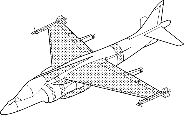
In another thread I mentioned that my group at McDonnell Douglas had come up with a supersonic STOVL fighter/attack airplane that we called Harrier 21. It was supposed to be one of a series of potential AV-8B follow-ons. There was Harrier III Low End, a modest modification of the basic AV-8B with limited gains in performance, and Harrier III Medium which was about as far as the basic airframe could be expanded. Both were subsonic because of the drastic transonic drag rise associated with the Harrier's fundamental layout. Harrier 21 was originally called Harrier III High End but since it was a completely new aircraft, that designation really didn't fit, hence Harrier 21, a new member of the Harrier family for the 21st Century.

I've written at length in other Harrier variant posts about the process of creating the configuration, so I won't repeat that here. But I didn't reveal any images other than one front view that had been posted by someone else in a batch of Harrier line drawings. I can't see any harm in posting this picture though, it doesn't reveal any technical details, just the general shape of the aircraft. I painted it at the time, 1991, and I'm not sure that it even represents the final configuration, but it's what was being looked at during my involvement. I'm no artist, and the painting is rather crude, I didn't even bother to prime the canvas board to get rid of the cloth texture and give a smooth surface. Still, I hope this will be of interest to anyone who's interested in "never-never" Harrier derivatives, or what might have been if only ASTOVL hadn't shut us down. :)
 

Attachments

  • 1749930038989.png
    1749930038989.png
    2.3 MB · Views: 3,056
Last edited by a moderator:
Fantastic view ! Thank you !

Did you ever speak about the Harrier III Medium on another thread ?
Just briefly, what I could remember from 30-something years ago. It had a stretched fuselage to reduce distortions of incoming air at the engine fan face as well as to make room for more internal fuel, and the so-called "big wing" for more area and weapon pylons, but its main distinguishing feature was a dorsal spine, also for more fuel or avionics or something. Very much a subsonic machine. Also a change in gun pods but the weapons we were going to use never actually got developed. There was another thread with this info but I can't find it now. Somebody who's better at searching than I am could probably locate it. :) This was the pic that was in the post though, I had enough sense to save it, at any rate.
 

Attachments

  • 1750001481142.png
    1750001481142.png
    64.3 KB · Views: 2,364
Last edited by a moderator:
Was the Harrier 21 a three poster?
I'm very mindful of State Department ITAR issues, after spending 42 years in the defense support environment, so I'm hesitant to say anything about the technical details this even though Harrier 21's propulsion system was 100% a Rolls Royce design/development. The RB.578 (Pegasus -408 core for H21 prototype) and RB.571 (EFA core for H21 production aircraft) should be documented somewhere in Rolls Royce's archives but I haven't been able to find anything. I got in touch with Pete Pavey, head of the Rolls Royce Heritage Trust, last year about this and he wasn't aware of any surviving material either. But maybe the RR and BAe people who we worked with on H21 were interested enough to hang onto some of the documents. There was a data package with 3-views of the aircraft and each of its major subsystems separately, along with a set of tables containing the requirements and performance numbers. There was also a lovely blueprint of the aircraft, at least in its MDC-generated form, although I'm not sure that it represented the final merged configuration between what MDC had done and BAe's somewhat different layout. I can't be the only one who saved these things, surely somebody in the UK did. Anyone have any contacts they could check with?
 
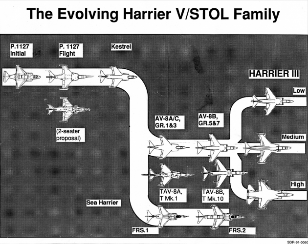
Found this today, something I created in 1991 to show how our "Harrier III" variants fit into the overall Harrier evolution line. As you can see, the H21 (Harrier III High End) didn't really fit at all, it was a whole new thing, which is why ASTOVL took such umbrage to it. It's not the best reproduction, but the original was made in the days when "cut and paste" was literally what we had to do, before things like PowerPoint. Each of those little silhouettes was painstakingly cut out from a photocopy and stuck onto the base paper with glue. The shaded areas were done with a peel-and-stick product that you used to be able to buy at stationery stores, back when they were a thing.
 

Attachments

  • 1750347851574.png
    1750347851574.png
    3.8 MB · Views: 2,359
Last edited by a moderator:
How did I miss this thread for a month!

I’ve been obsessed with what a Harrier 21 looks like since stever_sl mentioned it in the Advanced Harrier Projects thread.

I even posted a new doodle of what I thought it looked like a couple of days ago but that seems to have been removed.

Great to see the real thing. Thanks so much for sharing your knowledge stever_sl
 
Found this today, something I created in 1991 to show how our "Harrier III" variants fit into the overall Harrier evolution line. As you can see, the H21 (Harrier III High End) didn't really fit at all, it was a whole new thing, which is why ASTOVL took such umbrage to it. It's not the best reproduction, but the original was made in the days when "cut and paste" was literally what we had to do, before things like PowerPoint. Each of those little silhouettes was painstakingly cut out from a photocopy and stuck onto the base paper with glue. The shaded areas were done with a peel-and-stick product that you used to be able to buy at stationery stores, back when they were a thing.

View attachment 775123
Is that "twin-tailed F-16" shape somewhat representative of the Harrier 21 design?
 
Is that "twin-tailed F-16" shape somewhat representative of the Harrier 21 design?
The painting a few posts up actually IS the Harrier 21, as it existed at one point in time. It may have morphed somewhat when the MDC and BAe designs were combined. As someone pointed out, it's not a million miles apart from a single-seat T-7 in overall configuration.
 
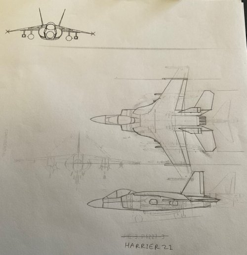
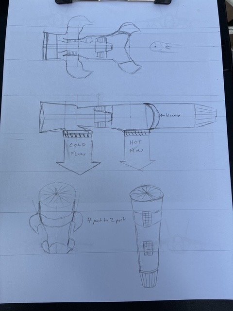
I came up with this on Sunday, before I realized there was a Harrier 21 thread. I posted it in the Advanced Harrier Projects thread but it seems to have disappeared.

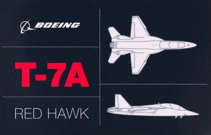
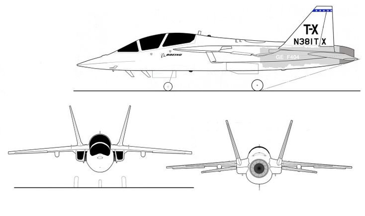
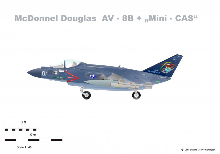
I drew over the plan of the P1227-3 from that thread and gave it T-7A Red Hawk style aft fuselage and cropped the wings to match the front view. Also extended the intakes and guessed what the LERX looked like. Came out looking similar to the mini-CAS Harrier from the side!

No idea where the undercarriage goes and left it as a four poster. I expect something similar was looked at on the road to the actual Harrier 21 configuration?

(Edit - resized images)
 

Attachments

  • IMG_0243.jpeg
    IMG_0243.jpeg
    52.7 KB · Views: 655
  • IMG_0242.jpeg
    IMG_0242.jpeg
    51.9 KB · Views: 626
  • IMG_4242.jpeg
    IMG_4242.jpeg
    400.9 KB · Views: 109
  • IMG_0230.jpeg
    IMG_0230.jpeg
    832.8 KB · Views: 101
Last edited:
Found this today, something I created in 1991 to show how our "Harrier III" variants fit into the overall Harrier evolution line. As you can see, the H21 (Harrier III High End) didn't really fit at all, it was a whole new thing, which is why ASTOVL took such umbrage to it. It's not the best reproduction, but the original was made in the days when "cut and paste" was literally what we had to do, before things like PowerPoint. Each of those little silhouettes was painstakingly cut out from a photocopy and stuck onto the base paper with glue. The shaded areas were done with a peel-and-stick product that you used to be able to buy at stationery stores, back when they were a thing.

View attachment 775123

The wing on 'High' looks very like that of the F16. Or am I mistaken?
 
The wing on 'High' looks very like that of the F16. Or am I mistaken?
Just a generic trapezoidal wing, or "cropped delta" as I think Roy Braybrook once called the F-16's. I could ask our designer if there was any inspiration beyond that but I never heard anything at the time about being inspired by any particular aircraft's wing.
 
I can't see any harm in posting this picture though, it doesn't reveal any technical details, just the general shape of the aircraft.
Would you to draft some rough sketches of your vision of the 21 from a few other angles? I've kept an eye on these threads for material to create a 3D model of the 21. The version you painted is what I'd like to create, but I'm struggling to piece together what the undercarriage would look like from scattered previous posts. I'm not the most creative person, unfortunately, and struggle a bit without references. Nothing else has been posted for a while, so I figured that might be something I could ask without causing any trouble for you. Again, I'm just after the general shape, which is just enough to recreate faithful topology of it. It would be very helpful and well appreciated.
 
Would you to draft some rough sketches of your vision of the 21 from a few other angles? I've kept an eye on these threads for material to create a 3D model of the 21. The version you painted is what I'd like to create, but I'm struggling to piece together what the undercarriage would look like from scattered previous posts. I'm not the most creative person, unfortunately, and struggle a bit without references. Nothing else has been posted for a while, so I figured that might be something I could ask without causing any trouble for you. Again, I'm just after the general shape, which is just enough to recreate faithful topology of it. It would be very helpful and well appreciated.
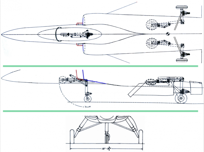
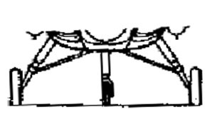
I'm still hesitant to show much in an international forum, but this is what the landing gear looked like. You can tell where things are located by the lower edge of the inlet duct lip. It's not the best quality image, it's taken from an information package from 30+ years ago, but it gives the general idea. The nose gear retracted to the front, the main gear retracted forward too but rotated nearly 90 degrees to lie flat in the limited available space in that part of the fuselage. I can provide clearer views from an inboard profile 3-view but I'll have to do some extensive sanitation first, and it may be a few days before I can get it done. We have family visiting this week, we haven't seen them for 2 years so we're pretty busy.
1754944394102.png
 
I'm still hesitant to show much in an international forum, but this is what the landing gear looked like. You can tell where things are located by the lower edge of the inlet duct lip. It's not the best quality image, it's taken from an information package from 30+ years ago, but it gives the general idea. The nose gear retracted to the front, the main gear retracted forward too but rotated nearly 90 degrees to lie flat in the limited available space in that part of the fuselage. I can provide clearer views from an inboard profile 3-view but I'll have to do some extensive sanitation first, and it may be a few days before I can get it done. We have family visiting this week, we haven't seen them for 2 years so we're pretty busy.
View attachment 781224
Please and thank you!
 
I'm still hesitant to show much in an international forum, but this is what the landing gear looked like. You can tell where things are located by the lower edge of the inlet duct lip. It's not the best quality image, it's taken from an information package from 30+ years ago, but it gives the general idea. The nose gear retracted to the front, the main gear retracted forward too but rotated nearly 90 degrees to lie flat in the limited available space in that part of the fuselage. I can provide clearer views from an inboard profile 3-view but I'll have to do some extensive sanitation first, and it may be a few days before I can get it done. We have family visiting this week, we haven't seen them for 2 years so we're pretty busy.
View attachment 781224
I found time to clean up the inboard profile and trim it down to just the areas around the landing gear, so it doesn't show anything but that, and there's no way those could be considered sensitive information! On the side and top views I've highlighted the inlet lip in blue and the splitter plate in red because it's a little unclear which lines represent what in the side view, so this gives points of orientation. I've also included the front air dam plate in the side view because it was intended to come down in vertical landing mode, so then it was technically part of the alighting gear. It didn't appear in the top or front views on the original drawing so unfortunately the side view depiction is all I had. In the top view, I left in the canopy, again for reference and because it couldn't be considered sensitive by any reasonable person. I didn't include it in the side view because the inboard profile had massive amounts of detail in the cockpit area, every little line of which I'd have had to digitally erase, and none of which had anything to do with the original request for landing gear info anyway. The front view is also odd because it only shows the LH door. No idea why the RH one wasn't depicted there; it should have been.

You'll notice that in the top view there are a couple of parallel diagonal lines running out from the main landing gear struts and then just stopping without connecting to anything. That's how they're depicted in the original. I assume they're the diagonal bracing struts that appear in the front view and side view but whoever drafted the inboard profile never got around to showing exactly where they terminated.

The dimensions aren't very revealing of anything sensitive, so here are the "box" sizes for the total aircraft: Overall length 56' 0", wing span (without tip missiles) 31' 10 5/8" (why couldn't we have just gone to an even 32', I wonder?) and height of 16' 9 1/2" measured from the reference ground line to the tip of the vertical tail. There's one dimension for the landing gear on the front view that should help visualize things. Hope all this helps!
 

Attachments

  • 1755010574645.png
    1755010574645.png
    351.8 KB · Views: 1,502
Last edited by a moderator:
Just had a flick through my copy of Andrew Dow’s book Pegasus - Heart of the Harrier and spotted a proposed development of the Pegasus with two nozzles on one side only (one cold, one hot).

I had the thought that if you rotated the engine 90 degrees so the nozzle holes point straight down and fitted a thrust vectoring vane box nozzle to both you could have a much narrower V/STOL package for the straight through Pegasus derived engine for the Harrier 21.

(Edit - resize image)
 

Attachments

  • IMG_4243.jpeg
    IMG_4243.jpeg
    59.6 KB · Views: 91
Last edited:
I'm still hesitant to show much in an international forum, but this is what the landing gear looked like. You can tell where things are located by the lower edge of the inlet duct lip. It's not the best quality image, it's taken from an information package from 30+ years ago, but it gives the general idea. The nose gear retracted to the front, the main gear retracted forward too but rotated nearl

y 90 degrees to lie flat in the limited available space in that part of the fuselage. I can provide clearer views from an inboard profile 3-view but I'll have to do some extensive sanitation first, and it may be a few days before I can get it done. We have family visiting this week, we haven't seen them for 2 years so we're pretty busy.
View attachment 781224
Thank you very much, it's really appreciated. And apologies for such a late reply, I've been swamped with work the past few weeks. I look forward to working on this.
 
Last edited by a moderator:
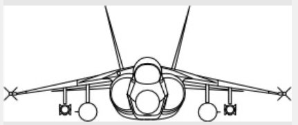
If you look carefully at the side view in stever_sl’s post #18 you can see what looks like the forward fin section of an AMRAAM at the top of the main gear leg. You can also see missile type objects in the forward view in post #16 in a similar position.

To me, it looks like the Harrier 21 had at least two side conformal AMRAAM stations. So, I think it unlikely it had any traditional or deployable side nozzles.
 
If you look carefully at the side view in stever_sl’s post #18 you can see what looks like the forward fin section of an AMRAAM at the top of the main gear leg. You can also see missile type objects in the forward view in post #16 in a similar position.

To me, it looks like the Harrier 21 had at least two side conformal AMRAAM stations. So, I think it unlikely it had any traditional or deployable side nozzles.
I'm not sure if those are conformal to the fuselage or on the wings.
 
If you look carefully at the side view in stever_sl’s post #18 you can see what looks like the forward fin section of an AMRAAM at the top of the main gear leg. You can also see missile type objects in the forward view in post #16 in a similar position.

To me, it looks like the Harrier 21 had at least two side conformal AMRAAM stations. So, I think it unlikely it had any traditional or deployable side nozzles.
There were reasons. :)
 
I'm not sure if those are conformal to the fuselage or on the wings.
Hmmm… good point. The wing hard points do look to carry weapons at a similar level.
 

Attachments

  • 1754944394102.jpeg
    1754944394102.jpeg
    14.6 KB · Views: 284
  • IMG_0180.jpeg
    IMG_0180.jpeg
    37.5 KB · Views: 289
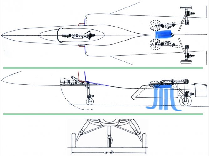
I would also speculate that there is a F-35B style Variable Area Vane Box Nozzle (VAVBN) in the area highlighted blue :)

It does look a bit tight between the main gear but I guess the area of the nozzle would roughly match the area of the two front nozzles on a Pegasus.
 

Attachments

  • 1755010574645.jpeg
    1755010574645.jpeg
    151.6 KB · Views: 373
I would also speculate that there is a F-35B style Variable Area Vane Box Nozzle (VAVBN) in the area highlighted blue :)

It does look a bit tight between the main gear but I guess the area of the nozzle would roughly match the area of the two front nozzles on a Pegasus.
That whole part of the aircraft was designed around the engine/nozzle layouts provided by Rolls Royce. I can tell you that the front "cold" flow was ejected well forward of the landing gear though. If anyone has contacts at RR you might ask them for information about their RB.578 (Pegasus core for X-plane demonstrator) and/or RB.571 (Eurofighter engine core for production Harrier III) although I've tried myself and haven't had any success. Pete Pavey, Hon Gen Secretary of the Rolls-Royce Heritage Trust (RRHT) since 1990, wasn't able to find anything either. But surely somewhere something still exists. If not there, then at British Aerospace, our design partners for the airframe and subsystems.
 
I take back what I said about the front view. It's not the Medium after all.
So is it the High or somewhere on the way to it? It still looks very Harrier like but has the twin tails. I think the front view matches the plan view in regard to the span of the wings and tails at least.
 
So is it the High or somewhere on the way to it? It still looks very Harrier like but has the twin tails. I think the front view matches the plan view in regard to the span of the wings and tails at least.
It's the High, I just had to go back and look at the drawings again to confirm it because after decades of looking at boxy inlet ducts, the rounded ones looked so weird!
 
I always wondered if they ever thought about a shaft driven system up front like demonstrated on Yak-41 then later X-35. Surely nobody decided it could not be done without trying.
 
I always wondered if they ever thought about a shaft driven system up front like demonstrated on Yak-41 then later X-35. Surely nobody decided it could not be done without trying.
Despite what everyone seems to believe about who "invented" shaft-driven lift fans, they were always in the potential design space for next-gen VTOL as we called it then, before it became V/STOL and finally settled down to today's STOVL (where you'll notice the idea of VTO has been quietly retired.) We didn't need it for Harrier III High End, we had the bases covered there with direct lift from the engine. But when I transitioned over to ASTOVL we very definitely knew about shaft drive, and knew that it was the only way to get a viable lift fan configuration. The alternative, called "gas-coupled lift fan" or GCLF, took up huge internal volumes due to the need to run gas forward from the engine to the fan, as opposed to SDLF (shaft driven lift fan) which only needed a tiny bit of room for the shaft and any gearboxes that might be required at each end. We were required to submit a proposal for each type of fan drive, as was Lockheed, and one of us was going to get the SDLF contract and the other the GCLF. It was a tremendous shock when we found out that we were stuck with the GCLF. We knew we couldn't make GCLF competitive in cost or weight or reliability or total life cycle cost. There was talk of using Company money to develop our own SDLF configuration in parallel with the GCLF, but that came to nothing. We had no way of knowing that the whole ASTOVL "competition" was nothing more than a cover story to keep the secret that DARPA and others had been funding SDLF studies by Lockheed for years, and that we'd been wasting our time trying to squeeze into that already-running effort with our own concept. ASTOVL went nowhere as a program, it got rolled together with other things that morphed into JAST and finally JSF. To my knowledge, lift fans weren't looked at again by McDonnell or Boeing for tactical fighter/attack STOVL after ASTOVL. We certainly didn't put them into the MDC/BAe/Northrop JAST configuration; we (and I mean our management) stupidly insisted on explaining to the Marines why they were wrong about not accepting any such airplane that had more than one engine, i.e. the lift engine that we (again, our management, not the rest of us) used in our STOVL variant. And JSF was even worse, thanks again to management ignoring USMC's insistence on having just a single engine. It was a direct-lift design with no SHP left over to drive a fan, so when the lift couldn't be made to work with the aircraft's weight, the geniuses running the program put in a whole bunch of little downward-pointing jet engines that they called "Lift Thrust Augmentors" instead of admitting what they were. Mind you, there was a way to get the weight down so that we didn't need LTAs; I was a very minor member of the team that came up with a revised aft nozzle design that did the trick. But the powers that be had committed to the LTAs and didn't want to hear about a different main nozzle. That was one heck of a stormy meeting! Those of us on the call in St Louis knew, by decades of coordination with the Marines, that the LTAs doomed our proposal. We put our conference phone on mute and went back to our desks, but my cubicle was right outside the conference room and I heard the rest of the meeting. There was absolute consternation about the effects that the LTAs were going to have on subsystem integration among other things. And yet when the day came for the announcement of who had won JSF, I was sitting next to our program manager in the cafeteria along with hundreds of other people, and it was clear that he thought we were going to win. I truly think that he was the only one in the room who shared that belief. About 5 minutes before the announcement was made, he was called behind the curtains at the front of the room, and emerged a minute later looking absolutely devastated. It was one of the saddest days of my whole 42-year career, and yet the rank and file had known what was bound to happen with our STOVL design.
 
Steve
I very briefly (just before leaving RR) worked on an engine dec for a pancake GCLF architecture, two fan stages driven by tip turbines (no connection shaft) at half the thrust of our main cylindrical offering. I assumed it was for packaging within strakes so was duplicated port and starboard. The small outer diameter worked a little better with matching the rotor dynamics. We rarely or never got to see the aircraft configuration. Not sure if this was in response to a MDC or BAe request/proposal. Do you remember any such scheme?
 
When I worked at LM-Aero, here in Fort Worth, I talked to one of their aerodynamicists who stated they were more more afraid of competition from St. Louis than from Boeing,
If you mean during the first-round JAST downselect, when MDA was teamed with BAe and Northrop, there was good reason to fear what St Louis could do, technically. But that team never found its footing. Work split between the companies was a big problem. For reasons I will never understand, selecting the STOVL variant's vertical lift propulsion method was allocated to Northrop, who had never done a production VTOL anything, rather than either of the 2 other team companies which between them had 100% of the actual US/UK VTOL production experience. That doomed our JAST proposal. The configuration itself was a lovely thing (in my eyes) but its lift engine made it impossible for the Marines to accept it, no matter how much more efficient Northrop insisted it was than other solutions. Boeing's dark-horse win in that competition came out of nowhere and their design was, to put it bluntly, silly.

If you mean the final JSF downselect, St Louis wasn't in the driver's seat at all, Puget Sound was. We (St Louis) wasted months trying to get them to understand that their tailless thing might be OK for the land-based variant and maybe even for the STOVL variant but not for the naval variant. Without going over that ground again, I'll just say that there are significant issues with having all of your pitch and roll and high-lift controls concentrated on one trailing edge, when it comes to landing aboard a ship at night in rough weather. St Louis had decades of experience with shipboard fighter/attack, Seattle had none, but what we kept being told was "if you're so smart, why did you lose JAST? Why did we get to buy you instead of the other way around?" It didn't help that the tailless configuration was patented by PS people, including one who would in later years go on to become Boeing's CEO, putting much pressure on keeping the X-32 design within the patent's protective parameters. St Louis's experience with shipboard operations, STOVL technologies, and in fact tactical jet fighter/attack knowledge (and how to deal with a Government customer rather than commercial ones) were all just held in low regard by PS management, at least that's how it seemed to us. Remember that the last Boeing fighter that made it into production was the P-26 of 1932, while we had multiple production lines running for all 3 US Services and many foreign customers as well. It was frustrating, and in the end fatal to our ability to develop a winnable design.
 
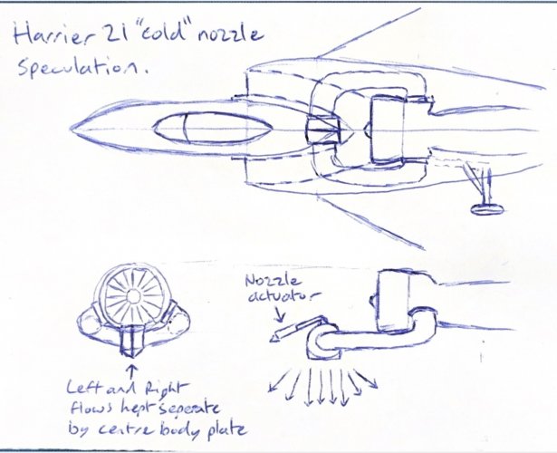
Late night doodle of how I think the forward “cold” nozzles on the Harrier 21 might be installed.

(Obviously another blatant attempt to get more info from stever_sl :))
You may be right, but I really hate the two turns. Every turn in the pipes costs thrust when you're trying to deadlift the entire plane. It's why IIRC the Pegasus turns are only a pair of 45s.
 
You may be right, but I really hate the two turns. Every turn in the pipes costs thrust when you're trying to deadlift the entire plane. It's why IIRC the Pegasus turns are only a pair of 45s.
Sometimes we have to do things that we'd rather not do, and just eat the penalties if the overall benefits seem to outweigh them. In this case, speaking hypothetically of course, it might be OK to take a modest loss with the "cold" front nozzles in hover if that allowed you to move the engine way back in the fuselage so you could use a conventional nozzle with afterburner for cruising flight...hypothetically... :)
 
Sometimes we have to do things that we'd rather not do, and just eat the penalties if the overall benefits seem to outweigh them. In this case, speaking hypothetically of course, it might be OK to take a modest loss with the "cold" front nozzles in hover if that allowed you to move the engine way back in the fuselage so you could use a conventional nozzle with afterburner for cruising flight...hypothetically... :)
Fair point.

It's still ugly to me. The original Pegasus lift is so much more elegant.
 

Similar threads

Back
Top Bottom