Hi All,

Does anyone know of an accessible version of the Dec 1942 patent for the cranked wing, later appearing on the V16? It has eluded me so far.

Much appreciated!
 
Some E.395 images seem to have found their way into this thread, so I'll leave this here:
This seems to be the original drawing of the E.395 as seen in the Lockheed report. Found it here: https://polska-org.pl/6831343,foto.html

Apparently this was available at an online auction ().
 

Attachments

  • Dokumenty_Kamienna_Gora_6831343.jpg
    Dokumenty_Kamienna_Gora_6831343.jpg
    109.2 KB · Views: 583
On November 16, 1944 the OKL issued a specification calling for a Geführte Zhame Sau control aircraft able to vectoring a large number of night fighters against a ‘Bomber Stream’.

On December 16, 1944 the Arado Company proposed an Ar 234 C-5 jet bomber modified as airborne G.C.I. station with 360-degrees radar coverage and two crew members.

The new radar FuG 240/4 Berlin N4 with 400 rpm rotatory antenna offered a global panorama over a circular area with 18 km of diameter.

The rotating antenna was housed in the Obertasse, a saucer-shaped aerodynamic fairing with 1.5 m of diameter mounted above the fuselage.

In February 1945, a 1:10 scale wind tunnel model was tested at DVL-Berlin and AVA Göttingen facilities.

The FuG 350 Naxos ZR passive receiver would allow the flying G.C.I. to track the ‘Stream’ within 100 km range.

Arado Ar 234 C-5 Obertasse technical data

Wingspan: 14.41 m, length: 12.9 m, height: 4.15 m, wing area: 27 sq. m, max weight: 11,150 m, max speed: 800 km/h, range: 1,090 km, power plant: four BMW 003A turbojets each rated at 800 kg static thrust, armament: none, electronics: FuG 240/4, FuG 10P, FuG 15v+EiV7, FuG 16 Zy, FuG 25a, FuG 101a, FuG 120, FuG 125, FuG 136, FuG 222, FuG 350 ZR, Peil G VI, FuBl2.
 

Attachments

  • 213a.jpg
    213a.jpg
    346.3 KB · Views: 231
I remember seeing something about an Ar 234 project capable of launching V-1 missiles. Does anyone have info?
 
I remember seeing something about an Ar 234 project capable of launching V-1 missiles. Does anyone have info?
During the weeks that followed the D-Day, the ground forces of the Allies neutralized in their advance numerous launch sites of V-1 cruise missiles in northern France.

When the units of the Wehrmacht retreated eastward, the new frontiers of the Reich got progressively further from London. The V-1s launched from central Netherlands, with its maximum range of only 240 km, could no longer reach the British capital.

On July 9, 1944 the Luftwaffe intended to continue its bombing offensive launching the V-1 missiles from Heinkel He 111 obsolete bombers.

A number of He 111 H-21 bombers already on the assembly line, were modified to H-22 configuration to carry a single V-1 on a rack under either port or starboard wing. Other H-16 and H-20 series aircraft were also converted at Heinkel-Oschatz facilities.

The units in charge of the launches were III./KG3 (July 9 to September 15, 1944) and KG 53 (September 16, 1944 to January 14, 1945).

Taking off with great difficulty from the Dutch airfields of Gilze-Rijen, Venlo and Zwischenahn, these bombers ventured far into the North Sea to launch their missiles against English cities.

The V-1s came from the east, thus taking by surprise the British defenders that expected them from the south. At best, the Chain Home stations could give six minutes warning before the flying bomb reached the British coast.

To cope with the air-launched threat, in October 1944 the British defense system had to re-orientate with the center on the Thames Estuary.

Between July 1944 and January 1945 these Heinkels launched 1,600 missiles against London, Southampton, Gloucester, Manchester and Paris but the accuracy of air launches was far inferior to that of those made from ground sites.

The bomber flying at 160 ft. (50 m) over the sea to evade detection by coastal radar, and climbed to 1,500 ft. (450 m), the missile launch altitude.

During this maneuver, the Heinkel was detected by the Chain Home stations at North Foreland, St. Margaret Bay and Foreness, by radar ships and Flak cruisers patrolling in the middle of North Sea and by several Wellington bombers from Coastal Command fitted with ASV radars.

After the bomber was plotted in the control room of the radar station, the Fighter Control would warn the Allied night fighters that where in the area (about 25 miles away) vectoring them toward the intruder.

The air launch it was a dangerous work as some missiles exploded prematurely and others beat the bomber tail after the launch, because the air turbulence.

In mid-December 1944, the KG 53 lost twelve bombers in two days to launch accidents, a total of 77 H-22 bombers were destroyed by accidents or shot down by Allied fighters.

From the strategic point of view, the low frequency of launches was useless and the old Heinkel was easy prey for the all-weather interceptors Mosquito and Black Widow that searched them over the sea.

The Luftwaffe needed a faster launch plane and in October 1944 the DFS Institute began experiencing different systems of high-velocity towing so that the V-1s could be carried by the new Arado Ar 234C jet bombers. The system was named Deicheslschlepp and consisted of a rigid tow bar with joints at both ends that hold together the two planes.

With the Huckepack configuration the missile was transported on the back of the bomber. During launch, a system of bars held the aircraft together (without the risk of collision by turbulence) whilst the pulsejet ignition was made.

Startwagen consisted of a three wheeled cart on which the launch bomber was positioned, with folded undercarriage, and the missile within an aerodynamic pod that was suspended under the fuselage.

The production of the Ar 234 was slow because of the shortage of turbojets and only some prototypes of the C-Series were finally manufactured in 1945.

This V-1 version was to be used in Pulkzerstörer attacks steered by a new DFS radio-command from the Ar 234 pilot.

The Deicheslschlepp system was initially designed to tow auxiliary fuel tanks.
 

Attachments

  • Pictureyyyyo.jpg
    Pictureyyyyo.jpg
    284.7 KB · Views: 147
  • ggggi.jpg
    ggggi.jpg
    196.7 KB · Views: 135
  • Picture4.jpg
    Picture4.jpg
    212.4 KB · Views: 142
  • Picture5.jpg
    Picture5.jpg
    198.9 KB · Views: 137
  • Picture6.jpg
    Picture6.jpg
    159.3 KB · Views: 164
  • yyyy.jpg
    yyyy.jpg
    334.3 KB · Views: 187
From Deutche Luftwaffe site,which is no longer on Net.
 

Attachments

  • 25.png
    25.png
    573.9 KB · Views: 143
  • 26.png
    26.png
    450.4 KB · Views: 142
  • 20250404130842.pdf
    6.7 MB · Views: 69
Hi Hesham, the archive of this site was a great source of original documents. Have you also loaded down other documents?


Hi Basil,yes I did,but many of them are lost in my files
 
Does anyone know if a specific Arado bomber project would have had the exact wing sweep of the V.16? This link says it starts at 37 degrees and goes to 25 at the wingtips
As far as I'm aware it was a tech demonstrator not a prototype for an operational design, is this accurate?
Why the combined powerplant? Was it to reach the speed of the projected future bombers for accuracy?
 
From, Hamel_J_Aircraft_2005_Vol_42_No_4_July_A
 

Attachments

  • 3.png
    3.png
    236.7 KB · Views: 99
From, Hamel_J_Aircraft_2005_Vol_42_No_4_July_A

Figure from the paper "Birth of Sweepback: Related Research at Luftfahrtforschungsanstalt - Germany" by Peter G. Hamel, published on Journal of Aircraft Vol. 42, No.4 2005, pp. 801-813.
A very interesting paper with a lot of interesting pictures, this is the abstract:

An extended historical review is given about German World War II scientific and industrial research on the beneficial effects of wing sweep on aircraft design by reducing transonic drag rise. The specific role of the former Luftfahrtforschungsanstalt (LFA), which was located in Braunschweig-Voelkenrode, is emphasized. Reference is given to LFA’s partner research organization Aerodynamische Versuchsanstalt in Goettingen, the scientific birthplace of modern aerodynamics.Wind-tunnel facilities at LFA, which were taken out of existence afterWorld War II, are illustrated. Advanced missile research and aircraft support projects at LFA are illuminated. Further, the postwar technical know-how transfer and its implementation to U.S. and other international aircraft projects is highlighted together with contributions of some former German researchers to the advances of aeronautics.

PS: the same paper was presented in the proceedigns of the AIAA Atmospheric Flight Mechanics Conference and Exhibit,
11-14 August 2003, Austin, Texas.

The same picture apparead on page 536 of "German Development of the Swept Wing 1935-1945" as Figure 6.71, with a short description in the text:

"In 1942 Arado became interested in the application of the swept wing (see [4], p. 94). In the opinion of the chief aerodynamicist of Arado, R. Kosin, decisive for its use on the Arado Ar 234 was the overcoming of the stability problems of the swept wing in the high-lift regime. Aeronautical research was, at that time, mainly concerned with the flight behavior of the swept wing at high speeds. Only later did high-lift regime become of interest to scientists. Arado as well as Junkers had to acquire the needed data through their own investigations.
Kosin saw the solution to the problems within the high-lift regime in a wing whose sweep decreased from inboard to outboard. The lesser sweep of the outer wing provided sufficient aileron effectiveness at high angles of attack and, simultaneously, defused the so-called “tip-stall” problem. Arado registered this idea in 1942 for a patent, probably without knowing that A. Betz of the AVA had already patented the same idea in 1939 (see Sec. 2.3.3). This fact once more illustrates the poor communication between research and industry at that time. The characteristics of the new wing were investigated in the wind tunnels of the DVL, AVA, and LFA. A so-called “variable model” was used that could be equipped with different wings and engine arrangements. Figure 6.71 shows the Arado “variable model” in the A1 wind tunnel of the LFA Braunschweig-Völkenrode. Figure 6.72 shows a three-view drawing of the model scheduled for the Göttingen wind tunnels. As obvious in this figure, the wing possessed a slat in the area of the aileron. Figure 6.73 shows the wind-tunnel model equipped with two jet engines."

Here the following low-res figures 6.72 (taken from G. Brennecke, W. Keydell, Investigation of the Ar 234 model with swept wing, AVA Report 44/W49, 1944) and 6.73:

Ar 234 with swept wing.jpg

Wind-tunnel model Arado Ar 234 with swept wings.jpg
 
- By early 1945, the designer Hans Rebeski proposed to convert the four-engine prototypes Ar 234 V23 and V27 into interim night fighters Ar 234 C-3/N fitted with the same modifications of the B-2/N version.

The excess power was expected to compensate for the drag generated by the antennas and allow for the installation of heavy weaponry.

The C-Series had been designed with a new pressurized cabin to accommodate two crew members (sit staggered side by side) and two MG 151/20 cannons mounted under the floor.

The Ar 234 C-7 (December 16, 1944) was a night fighter project armed with two additional MG 108/30 cannons mounted in a ventral nacelle and with a FuG 244 radar airborne whose parabolic antenna was housed in an aerodynamic nose mounted radome.

Between 16 and 31 January 1945, the Arado Company proposed to the OKL the construction of the P-Series of heavy night fighters fitted with Bremen 0 radars and 30-mm guns mounted in the ventral position or in Schräge Musik configuration.

The P-1 model was basically a C-7 with new electronic equipment. The P-2, P-3, P-4 and P-5 versions were fitted with a new Panzerkabine armored cockpit.

The P-3 and P-5 models were powered by two HeS 011 turbojets in order to minimizing fuel consumption and increasing range.

The P-5 was redesigned to accommodate three crew members in order to adapt it to the February 26, 1945 specification.

By adopting the decision to use four turbojets, Arado lost the advantage of a longer range it had over the Messerschmitt Me 262 and the Ar 234 P was cancelled.

Arado Ar 234 C-3/N technical data

Wingspan: 14.10 m, length: 13.0 m, height: 4.3 m, wing area: 26.4 sq. m, power plant: four BMW 003 A-1 turbojets each rated at 800 kg static thrust, armament: two MG 151/20 rapid fire cannons mounted under the cockpit floor and two MK 108/30 heavy cannons housed in a ventral pod, electronics: one Siemens/FFO FuG 218 V2 (R) Neptun III VR AI radar fitted with Morgenstern eight dipoles mounted in ‘X’ antenna and backwards warning device with tail mounted Yagi antenna, frequencies 158 to 187 MHz, range 120 to 5,000 m, FuG 350 Naxos Zc, FuG 10P, FuG 15+EiV7, FuG 25a, FuG 125, FuG 101a, FuG 120a, Fu Bl3 Revi 16 N and Peil G6.


Arado Ar 234 P-5 technical data

Wingspan: 14.41 m, length: 12.84 m, height: 4.3 m, wing area: 26.2 sq. m, max weight: 6,530 kg, max speed. 873 km/h at 6,000 m, service ceiling: 12,000 m, range. 1,220 km, power plant: four BMW 003 A-1 turbojets each rated at 800 kg static thrust, armament: two MG 151/20 rapid fire cannons mounted under the cockpit floor and two MK 108/30 heavy cannons in Schräge Musik configuration, electronics: one Siemens/FFO FuG 244 Bremen 0 AI radar fitted with parabolic antenna, operation frequency between 3,250 and 3,330 MHz, range 200 to 5,000 m, FuG 350 Naxos Zo, FuG 15+EiV7, FuG 25a, FuG 125, FuG 120a, FuG 136, FuG 142, FuG 130, Revi EZ 42 Gnom and Peil G6.
 

Attachments

  • q.jpg
    q.jpg
    298.8 KB · Views: 97
  • w.jpg
    w.jpg
    309.1 KB · Views: 97
  • e.jpg
    e.jpg
    353.3 KB · Views: 95
  • r.jpg
    r.jpg
    283.2 KB · Views: 103
  • t.jpg
    t.jpg
    351.8 KB · Views: 95
  • y.jpg
    y.jpg
    223.9 KB · Views: 115
During the last year of the war in Europe, the Arado Company concentrated its efforts on the creation of several versatile multi-role aircraft.

These new designs depicted large aircraft capable of fighting American bombers by day, British bombers by night, flying in bad weather against D.H. Mosquitoes, attacking Soviet tanks at low altitude, or penetrating deep into heavily defended areas to bomb or photograph enemy installations.

On August 18, 1943, the Chief Designer Dr.-Ing. Walter Blume presented to representatives of the OKL the latest projects developed by the firm described in the internal document TEW 16/43. “T” means Technik und Konstruktion, “EW” signifying Entwurf (study) and “16“, the number of design series.

Arado TEW 16/43-19 was a preliminary study for the construction of a Stralhbomber (jet bomber) and a Nachtjäger (night fighter) powered by two turbojets.

Project 19 comprised three versions that differed in the type of turbojets used:

-Strahlbomber mit TL 1500 (Turbo-Lader) February 1943. It was powered by two Jumo 012 turbojets each rated at 2,780 kg static thrust. Wingspan: 16.2 m, length: 17.3 m, wing area: 46.6 sq. m, Max weight: 16,000 kg, range: 3,400 km.

-Strahlbomber mit TL 2000 (August 11, 1943) powered by two turbojets of unknown type. Wingspan: 19 m, length: 17.3 m, wing area: 64 sq. m, Max speed: 900 km/h with 2,000 kg of bombs.

-Strahlbomber mit TL 3000 (August 1943) powered by two turbojets of unknown type. Wingspan: 28 m, length: 17.3 m, wing area: 93 sq. m, Max speed: 940 km/h with 2,000 kg of bombs, range: 2,430 km.

The armament provided for all versions consisted of two forward firing MG 151/20 cannons; two rear firing MG 151/20 (fixed) and one MG 151/20 (flexible) mounted in a remotely controlled tail barbette FHL 151.

Arado TEW 16/43-22 was a preliminary study for the construction of a Zerstörer (heavy day fighter) armed with MK 213/20 and MK 103/30 cannons.

Arado TEW 16/43-24 was a preliminary study for the construction of a Kampfzerstörer (anti-tank) armed with MK 214/55 and BK 5/55 heavy cannons.

Arado TEW 16/43-26 was a preliminary study for the construction of a Schnellbomber (fast medium bomber) armed with two forward firing MG 151/20 cannons, two rear firing MG 151/20 (fixed) one MG 151/20 (flexible) mounted in a remotely controlled tail barbette FHL 151 and 2,000 kg bombs.

All these versions had a pressurized cabin that accommodated two crew members and were powered by two Jumo 012 turbojets.

In 1944 the four configurations were grouped together in the Arado E 560 project to simplify production by using as many common parts as possible.


E 560 was developed in at least eleven configurations with five specialized roles: Schnellbomber, Zerstörer, Nachtjäger, Schlechtwetterjäger and Zwangsaufklärer.

Only some information has been retained from six configurations:

E 560-2, Schnellbomber with two BMW 803 piston engine each rated at 4,000 hp, “T” tail, two crew members and 800 km/h.

E 560-4, Schnellbomber with swept back wings (25-degrees at ¼ chord), four BMW 003 E or Jumo 004C turbojets, two crew members housed in a pressurized cabin with 5-mm armor plates and 60-mm bullet proof glass, wingspan: 18.2 m, length: 17.6 m, height: 5 m, wing area: 48 sq. m, max weight: 17,000 kg, max speed: 900 km/h, range: 2,300 km, armament: two forward firing MG 151/20 cannons, two rear firing MG 151/20 (fixed) one MG 151/20 (flexible) mounted in a remotely controlled tail barbette FHL 151 and 2,000 kg bombs (external), electronics: FuG 10P, FuG 16, FuG 101, FuG 25a, K 12 autopilot and Kuto-nase (anti-balloons cable-cutter device).

E 560-7, Aufklärer (recce plane) with swept back wings (25-degrees at ¼ chord), powered by two turboprops BMW 028, Jumo 022 or Daimler-Benz DB 021.

E 560-8 (August 11, 1943), modified version of the TL 1500 project. Following the cancellation of the Jumo 012 turbojet and the awarding of all HeS 011 engine production to the Jägernotprogramm, it was proposed to use six BMW 003 A-1 turbojets, wingspan: 16.5 m, length: 18 m, height: 3.95 m, wing area: 46.6 sq. m, max weight: 16,000 kg, max speed: 920 km/h, range: 2,000 km, armament: two forward firing MG 151/20 cannons, two rear firing MG 151/20 (fixed) one MG 151/20 (flexible) mounted in a remotely controlled tail barbette FHL 151 and 3,000 kg bombs (housed in a bulged bomb bay), electronics: FuG 10P, FuG 16, FuG 101, FuG 25a, K 12 autopilot and Kuto-nase (anti-balloons cable-cutter device).

E 560-11 (December 1943), Schnellbomber with swept back wings (25-degrees at ¼ chord), designed to compete against the Blohm und Voss P. 188 and the Junkers Ju 286 jet bombers, powered by four BMW 018 turbojets each rated at 3,400 kg static thrust, wingspan: 24 m, length: 19.1 m, height: 5.1 m, max weight: 28,600 kg, armament: two forward firing MG 151/20 cannons, two rear firing MG 151/20 (fixed) one MG 151/20 (flexible) mounted in a remotely controlled tail barbette FHL 151 and 4,000 kg bombs (housed in a bomb bay), electronics: FuG 10P, FuG 16, FuG 101, FuG 25a, K 12 autopilot and Kuto-nase (anti-balloons cable-cutter device).


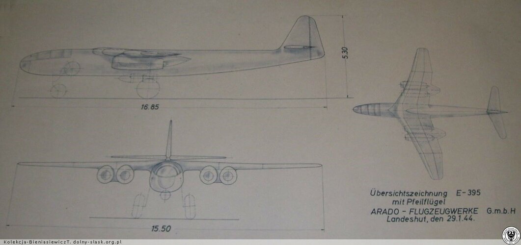
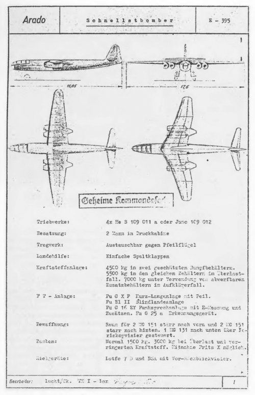
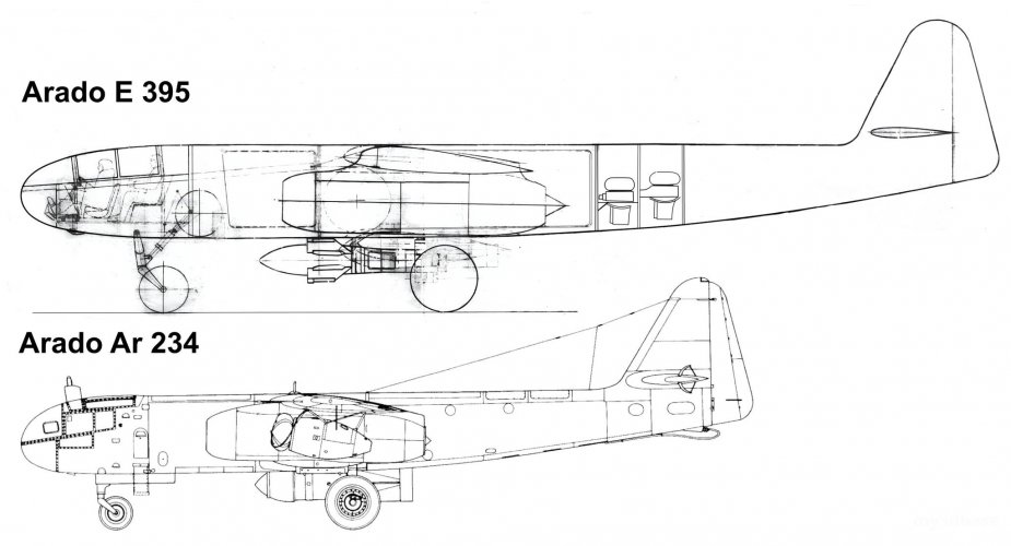
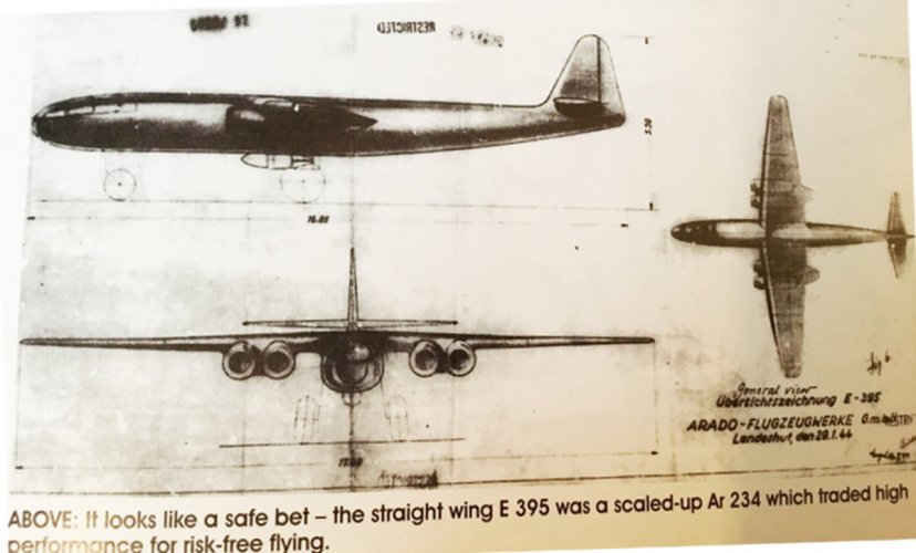
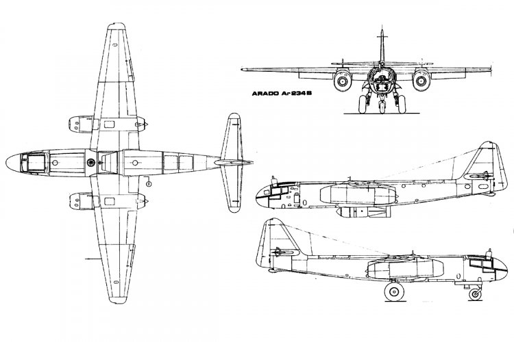
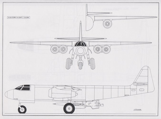
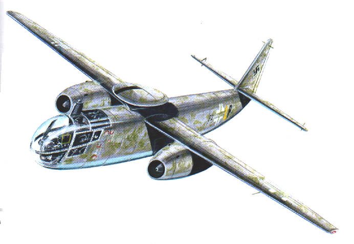
The E 395 project was a scaled-up version of the Ar 234 C, with two crew members housed in a pressure cabin, powered by four HeS 011 or Jumo 012 turbojets.

Two variants designed by Dipl.-Ing Lucht in competition with the Heinkel He 343 jet bomber, were proposed to the OKL:

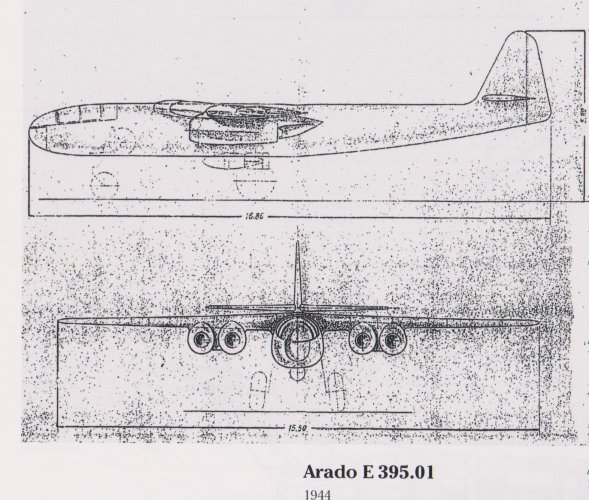
-E 395.01 (January 29, 1944) fitted with laminar-profile straight wing, wingspan: 17.6 m, length: 16.85 m, height: 5.3 m, wing area: 40 sq. m, max weight: 15,800 kg, max speed: 887 km/h at 6,000 m, service ceiling: 14,500 m, range: 1,500 km, armament: two forward firing MG 151/20 cannons, two rear firing MG 151/20 (fixed) one MG 151/20 (flexible) mounted in a remotely controlled tail barbette FHL 151 and 1,500 kg bombs (external) or one PC 1400 X missile, electronics: FuG 10P, Fu Bl 2, FuG 16 Zy, FuG 101, FuG 25a, K 12 autopilot, Lofte 7D, BZA and Kuto-nase (anti-balloons cable-cutter device).

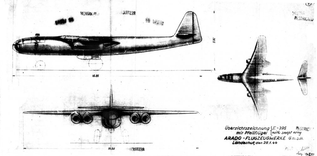
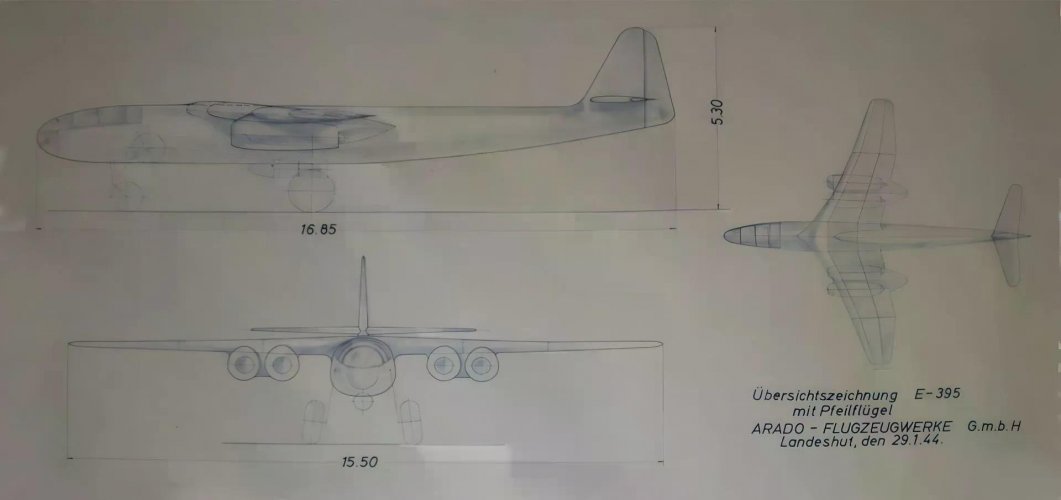
-E 395.01 (May, 1944) fitted with compound crescent wing developed by Dipl-Ing Kosin, wingspan: 15.5 m, length: 16.85 m, height: 5.3 m, max weight: 16,800 kg, max speed: 960 km/h at 7,000 m, range: 2,000 km, armament: two forward firing MG 151/20 cannons, two rear firing MG 151/20 (fixed) one MG 151/20 (flexible) mounted in a remotely controlled tail barbette FHL 151 and 3,000 kg bombs (external) or one PC 1400 X missile, electronics: FuG 10P, Fu Bl 2, FuG 16 Zy, FuG 101, FuG 25a, K 12 autopilot, Lofte 7D, BZA and Kuto-nase (anti-balloons cable-cutter device).

A prototype was expected to make the first flight on 31 December 1944, but the project was cancelled along with the Jumo 012 turbojet.

The E 395.02 (February 4, 1944) was a single-seat heavy day fighter with pressure cabin and stepped windshield, powered by two HeS 011 turbojets, wingspan: 14.4 m, length: 15 m, height: 5.1 m, max weight: 16,000 kg, max speed: 887 km/h at 7,000 m, range: 1,500 km, armament: two forward firing MG 151/20 cannons, two rear firing MG 151/20 (fixed) one MG 151/20 (flexible) mounted in a remotely controlled tail barbette FHL 151.

The project was cancelled following the OKL's decision to dedicate the entire production of the HeS 011 turbojet to the Jägernotprogramm.
 

Attachments

  • a.jpg
    a.jpg
    274.5 KB · Views: 117
  • b.jpg
    b.jpg
    196.4 KB · Views: 114
  • c.jpg
    c.jpg
    221.7 KB · Views: 132
  • kk.jpg
    kk.jpg
    99.2 KB · Views: 121
  • d.jpg
    d.jpg
    344 KB · Views: 125
  • e.jpg
    e.jpg
    145.1 KB · Views: 112
  • f.jpg
    f.jpg
    142.3 KB · Views: 107
  • h.jpg
    h.jpg
    139 KB · Views: 107
  • i.jpg
    i.jpg
    171.2 KB · Views: 126

Attachments

  • 1696001526724930-0.jpg
    1696001526724930-0.jpg
    228.4 KB · Views: 61
  • Ar E395.jpg
    Ar E395.jpg
    124.8 KB · Views: 63
  • 1696001522871302-1.jpg
    1696001522871302-1.jpg
    357.1 KB · Views: 58
  • Ar E395 straight wing.jpg
    Ar E395 straight wing.jpg
    509.6 KB · Views: 57
  • b_upscaled-1920w (2).jpg
    b_upscaled-1920w (2).jpg
    67 KB · Views: 23
Last edited:
Another E,395.

"The design proposal outlines two different engine configurations; with HeS 011 or Jumo 012. Drawings seem to depict a four engine configuration with HeS 011's with a total thrust of approximately 50kN. That value would be reached or exceeded with only two Jumo 012's. Leading to the conclusion that only two Jumo's were planned, despite the lack of information in primary sources to confirm that assumption. Only one drawing shows the Jumo version. But that sideview does not visualize the number of engines. "
 

Attachments

  • 511268761_10162862266952207_8799338598821741395_n.jpg
    511268761_10162862266952207_8799338598821741395_n.jpg
    553.9 KB · Views: 37
  • 513474497_10162862266792207_2372828626978065104_n (1).jpg
    513474497_10162862266792207_2372828626978065104_n (1).jpg
    523.6 KB · Views: 44
Last edited:

"Engines​

Only little information is available on the Jumo 012 engines. This Jumo engine configuration is the most interesting one however. There are only a handful of aircraft designs planned to use this engine which was in it's initial planning phase. Development of the engine was continued after WW2 in Russia. "
Jumo 012 side view.


Total 012 cross section.


Jumo 012A dimensions (Source http://hugojunkers.bplaced.net/junkers-jumo-012.html ):
Including 012A dimensions.
 
That means there was Ar.234P-6 ?.
must be
since RLM was not happy with Ar.234P-5 design
aerodynamic issue with engines, too high fuel consumption, weapons instalment.
what let to P-6 and P-7 design
 

Similar threads

Back
Top Bottom