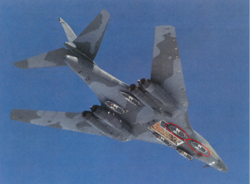
Nope, sweeping the wings all the way back to 90 degrees turning you to a lifting body was a 'thing' for a while. This model locates the pivots outboard to make it work.
 
PaulMM (Overscan) said:
Nope, sweeping the wings all the way back to 90 degrees turning you to a lifting body was a 'thing' for a while. This model locates the pivots outboard to make it work.

I particularly liked the scissor-wing, low-altitude, lifting body bomber.
 

The USN could use a F-111 replacement for the deck. Retiring that maintainence heavy craft ;} is just a mistake. Bones could help w/ the Pacific range problem
. Current and near future Carrier based craft carry is conspicuiously low.
A long range, near recoiless. gun suspended from a Bone could surpress IADs from distance.
 
Also found at NTRS -timeframe (1966) suggest that it was LAMP-AMP-AMPSS program related. My previous thoughts of TFX were re-thought:)
Too late and unusual for TFX. Beat me if I'm wrong.
TomS just pointed this one out from my verbal description in the oblique wing thread. There used to be a 1/48th scale (probably) model of this atop a cupboard in the flight controls office at BAE Systems Rochester. It had definitely been there since the GEC/GEC-Marconi Avionics days, and potentially all the way back to Elliott Avionics. It disappeared one weekend during some renovations (around about the millennium?) and hopefully it ended up in the Rochester Archives, not the skip, but I don't know.

My recall, and obviously I haven't seen it in 20 years and even then it was atop an 8' cupboard, is that the wing, fuselage and tail matched the picture flateric posted, but that the nose was a horizontal flattened wedge. But after 20 years I could be wrong.

The existence of the model at Rochester does seem to imply that the project was advanced enough to be talking to potential systems sub-contractors.
 
I'd always wondered how much cross pollination there was between Boeing's AMSA work and the 2707 SST. Scott's line drawing bears a strong resemblance to the Model 733 design from about 1964 or so, but there was an AWST article from '65 or '66 that mentioned specifically that there was little commonality between the Boeing AMSA design and the SST program other than a variable sweep wing. The USAF stated that there was little to gain on AMSA from the SST flight test program as there was a need to have the AMSA design frozen well before the SST would make its maiden flight.

Interestingly the Boeing historical archives has material on a 1964 briefing on the SST given at SAC Headquarters in Omaha and a later 1966 briefing given to the Pentagon's Weapons System Evauation Group (WSEG).
 
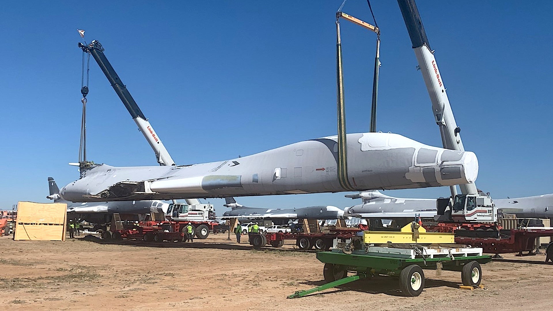
Anyone know what B-1B it was that got sent to the Boneyard?

The article talks at some length about the B-1B airframe that was taken from storage.

If you're asking about what airframes were placed in storage before, here is AMARC's inventory page for the B-1B:

 
Anyone know what B-1B it was that got sent to the Boneyard?

The article talks at some length about the B-1B airframe that was taken from storage.

If you're asking about what airframes were placed in storage before, here is AMARC's inventory page for the B-1B:


Thanks for the extra info TomS.
 
From Пономарев А. - Авиация на пороге в космос - 1971.
 

Attachments

  • a.png
    a.png
    40.6 KB · Views: 396
  • b.png
    b.png
    197.2 KB · Views: 327
,
It's hard to believe that scanning a physical object is the best way to build a digital model that will be used to understand the condition of the fleet. Each individual part differs from other examples within whatever tolerances were in effect when the part was produced. I'd think that it would be far better to work from the drawings, which include tolerencing representative of all examples and don't require disassembly.


Do they have the drawings? What condition are they in? What file format did they use? Is the CAD package still in existence? Do you know how long it takes to go from a drawing to a 3D printable model?
 
I would say that 3d scanning on the aircraft, won't help you much to predict fatigues and local strains without an extensive work that would require a full set of drawings. Then, the problem that you have starting with the drawing is that modelizing such complex assembly would cost you too much (time, workforce etc..) and will be met with quality escape and implemented design evolutions that might not be fully documented (those are complex projects).

A 3D scan will only allow you to match fit a part that had to be resourced or modified and check the validity of the new design in the assembly with local simulation. The name of the game is "Local".

Then eventually you can have a multi-pronged approach to rapidly rebuilt larger assemblies.
But the extend of the work will largely depend of the ressources you poor-in.

Here, the USAF IMOHO is more simply looking to document a serial representative airframe that contractors will be able to work with in their design, cutting cost of future modification or sustainement endeavors (part resourcing etc...).
 
,
It's hard to believe that scanning a physical object is the best way to build a digital model that will be used to understand the condition of the fleet. Each individual part differs from other examples within whatever tolerances were in effect when the part was produced. I'd think that it would be far better to work from the drawings, which include tolerencing representative of all examples and don't require disassembly.


Do they have the drawings? What condition are they in? What file format did they use? Is the CAD package still in existence? Do you know how long it takes to go from a drawing to a 3D printable model?

Scan output is a plot file that most software convert in a single surface file. You can easily 3D print that file directly if the model is suitable for the print process.

3d modeling from manufacturing drawings can be extensive with design evolution not always documented (various contractors manufacturing a single part through time for example).
Time needed greatly vary from a multi-parts per day to a week or more for a single part.

Often you'd need to re-invent the part trying to figure what exactly the process was and what are the compatible tolerances or quirks; that whithin a very short time. If you are serious, there can be a lot of documenting and FEA to match the part on hand.
It works well only if the project leader has a real knowledge of what this work involves. Sadly, too often, this work can be outsourced to contractors selected on the best offer per lots, leaving very few margins to do a proper work.
Agile billing is often needed but not quite well understood by the actors in presence.
 
Last edited:
,
It's hard to believe that scanning a physical object is the best way to build a digital model that will be used to understand the condition of the fleet. Each individual part differs from other examples within whatever tolerances were in effect when the part was produced. I'd think that it would be far better to work from the drawings, which include tolerencing representative of all examples and don't require disassembly.


Do they have the drawings? What condition are they in? What file format did they use? Is the CAD package still in existence? Do you know how long it takes to go from a drawing to a 3D printable model?

Scan output is a plot file that most software convert in a single surface file. You can easily 3D print that file directly if the model is suitable for the print process.

3d modeling from manufacturing drawings can be extensive with design evolution not always documented (various contractors manufacturing a single part through time for example).
Time needed greatly vary from a multi-parts per day to a week or more for a single part.

Often you'd need to re-invent the part trying to figure what exactly the process was and what are the compatible tolerances; that whithin a very short time. If you are serious, there can be a lot of documenting and FEA to match the part on hand.
It works well only if the project leaders has a real knowledge of what this work involves. Sadly, too often, this work can be outsourced to contractors selected on the best offer per lots, leaving very few margins to do a proper work.
Agile billing is often needed but not quite well understood by the actors in presence.


Yep. And this is why they're scanning the parts in. I wouldn't be surprised if there were software out there that could take a scan and auto-populate dimensions for tweaking. The kind of things scanning won't pick up are material properties. Was it machined from billet or a forging? What was the grain direction and material composition? Did it have heat treating or surface finishing? For geometry though scanning is light years away from trying to get the info from a drawing that may or may not exist.
 
But the scan output is a single file: there is no segegrated nuts, bolts, rivets, panels, ribs etc... All is blended into a single 3d model and you need to reconstruct what will be needed for you to use (interfaces, part that have an impact in your simulation, thickness of elements etc...).
Scanning is not a shortcut to design. It's a first step.

From the article, "Once the B-1B arrives at NIAR, researchers will 3D scan each part, "down to the nuts and bolts," to create a highly detailed virtual model that they can reassemble and disassemble at will on a computer."

They're going to tear it apart. Just waving a hand scanner over an assembled airplane would be useless. And nobody said it was a, "short cut to design". The design already exists. It IS however a much more efficient way than wading through a warehouse full of drawings and trying to update that mess to current CAD technology.
That part slipped through my mind in my attempt to put everything on the text. You are right... And, if that was not obvious in my reply, they do know absolutely what they are doing.
They might even use a library of modeled objects to cross reference the scan data and detect if a shape match the projection of a known part.
 
Last edited:
But the scan output is a single file: there is no segegrated nuts, bolts, rivets, panels, ribs etc... All is blended into a single 3d model and you need to reconstruct what will be needed for you to use (interfaces, part that have an impact in your simulation, thickness of elements etc...).
Scanning is not a shortcut to design. It's a first step.

From the article, "Once the B-1B arrives at NIAR, researchers will 3D scan each part, "down to the nuts and bolts," to create a highly detailed virtual model that they can reassemble and disassemble at will on a computer."

They're going to tear it apart. Just waving a hand scanner over an assembled airplane would be useless. And nobody said it was a, "short cut to design". The design already exists. It IS however a much more efficient way than wading through a warehouse full of drawings and trying to update that mess to current CAD technology.
That part slipped through my mind in my attempt to put everything on the text. You are right... And, if that was not obvious in my reply, they do know absolutely what they are doing.
They might even use a library of modeled objects to cross reference the scan data and detect if a shape match the projection of a known part.

Hopefully somebody has a BOM and assembly tree structure somewhere. :eek:
 
Of course I read it my dear Flateric,

but there was no exactly identification precisely.
 

Attachments

  • AMSA-1967-speculative concept.png
    AMSA-1967-speculative concept.png
    1.1 MB · Views: 373
OK everyone.... here is one I just acquired. A General Dynamics AMSA proposal. Only needed a little paint touch up to make him all pretty. About 22 inches in length and of wood construction. Wings do their thing too...... enjoy.
 

Attachments

  • IMG_7274.jpg
    IMG_7274.jpg
    2.6 MB · Views: 351
  • IMG_7273.jpg
    IMG_7273.jpg
    2.6 MB · Views: 339
  • IMG_7275.jpg
    IMG_7275.jpg
    2.4 MB · Views: 391

Similar threads

Back
Top Bottom