thanks for the reply! I was originally thinking along the lines of XFV-12 with its pretty disastrous thrust losses, but on second thought RR’s ducting is much larger diameter and with much less sharp curves so it makes sense to be less lossy.
It's actually a lot more like the approach that McAir was forced by DARPA to take with the gas-coupled lift fan ducting for ASTOVL. The main problem with ducting like that is that it takes up so very much internal volume that would otherwise be available for fuel. As a result, you have to make the fuselage bigger in cross-section to accommodate both, which increases both weight and drag. We had no choice on Harrier 21 because we had to stick with an unmodified engine core; nobody was funneling us secret funding to develop one that we could extract shaft horsepower from, like Lockheed was getting. :)
 
It's actually a lot more like the approach that McAir was forced by DARPA to take with the gas-coupled lift fan ducting for ASTOVL. The main problem with ducting like that is that it takes up so very much internal volume that would otherwise be available for fuel. As a result, you have to make the fuselage bigger in cross-section to accommodate both, which increases both weight and drag. We had no choice on Harrier 21 because we had to stick with an unmodified engine core; nobody was funneling us secret funding to develop one that we could extract shaft horsepower from, like Lockheed was getting. :)
Yes I remember reading about that from your posts, McAir really did get the short stick ☹️

Still, I think Harriet 21 turned out to be a pretty good-looking and capable design, shame it didn’t get built
 
Yes I remember reading about that from your posts, McAir really did get the short stick ☹️

Still, I think Harriet 21 turned out to be a pretty good-looking and capable design, shame it didn’t get built
If it had, then the USMC/RN need for a supersonic STOVL fighter/attack aircraft would have been met for the 21st Century, and JAST/JSF would have been just land- and sea-based CTOL aircraft. MCAIR's CTOL variants did great in the first-round downselect, it was the STOVL variant with its lift engine that cost them a win, so minus that variant things probably would have gone a lot better for them. It's my hunch that MCAIR and Lockheed would have been downselected while Boeing's unsolicited proposal would have been rejected, for risk levels if nothing else, given that they hadn't built a fighter in more than half a century. In that case MCAIR would have gone into the final JSF competition phase with a much stronger position and could have won there too. Instead of Boeing buying a critically weakened MDC in 1997, the post-9/11 collapse in airliner orders would have hit Boeing a lot harder than MDC, which had its Defense sector to prop it up as its Commercial sector suffered; Boeing had no such thing, and so it's entirely possible that the takeover would have proceeded, but in the other direction. All (potentially) because mid-level project managers decided to cancel Harrier 21 and focus on ASTOVL.
 
I wonder if Rolls Royce ever tested a Pegasus engine with throw forward ducts and the combined centre nozzle? Seems like a doable project for a testing rig.
 
I wonder if Rolls Royce ever tested a Pegasus engine with throw forward ducts and the combined centre nozzle? Seems like a doable project for a testing rig.
I'm pretty sure they never did put it into hardware. They would have needed a customer, or at least a potential one. After we got axed there was just ASTOVL, but the proposed engine core for that wasn't Pegasus. In a perfect (honest) world RR might have approached DARPA but that wouldn't have done them any good since DARPA was running their own black program to develop LiftFan as the path forward to high-speed STOVL.
There were 2 times in my 42-year career when I thought we could have changed the future of aviation. Harrier 21 was the first, and then a few years later Canard Rotor Wing, whose failure was purely a self-inflicted wound by MDC/Boeing management. I'm still frustrated and angered by both debacles.
 
Last edited:
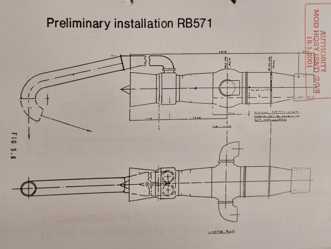
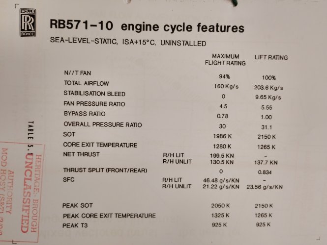
I've had some RB571-10 material declassified. See attached.

The UK drew various designs around this engine in 1989, some more like the designs @stever_sl posted than others.

Peter Calder spent a few years pushing the idea of a five-nozzle Pegasus, with a ventral nozzle added that was used in vertical flight to kill the hot gas fountain. The RB571 is, sort of, an extension of this idea. The Harrier design team at Kingston saw some issues in designing a Harrier variant around the five nozzle idea though (basically, another big hole in the structure was not easy).

Some of this story is told in my book (www.jumpjetpenguin.com). It all relates to the US/UK ASTOVL studies and the shock the UK suffered when they saw the McDonnell 'cactus' engine design from St Louis. See https://www.secretprojects.co.uk/th...d-mcdonnell-bae-astovl-entry.2219/#post-18661

 

Attachments

  • IMG_20260809_123040.jpg
    IMG_20260809_123040.jpg
    2.6 MB · Views: 150
  • IMG_20260809_123022.jpg
    IMG_20260809_123022.jpg
    1.3 MB · Views: 153
Last edited:
I've had some RB571-10 material declassified. See attached.

The UK drew various designs around this engine in 1989, some more like the designs @stever_sl posted than others.

Peter Calder spent a few years pushing the idea of a five-nozzle Pegasus, with a ventral nozzle added that was used in vertical flight to kill the hot gas fountain. The RB571 is, sort of, an extension of this idea. The Harrier design team at Kingston saw some issues in designing a Harrier variant around the five nozzle idea though (basically, another big hole in the structure was not easy).

Some of this story is told in my book (www.jumpjetpenguin.com). It all relates to the US/UK ASTOVL studies and the shock the UK suffered when they saw the McDonnell 'cactus' engine design from St Louis. See https://www.secretprojects.co.uk/th...d-mcdonnell-bae-astovl-entry.2219/#post-18661
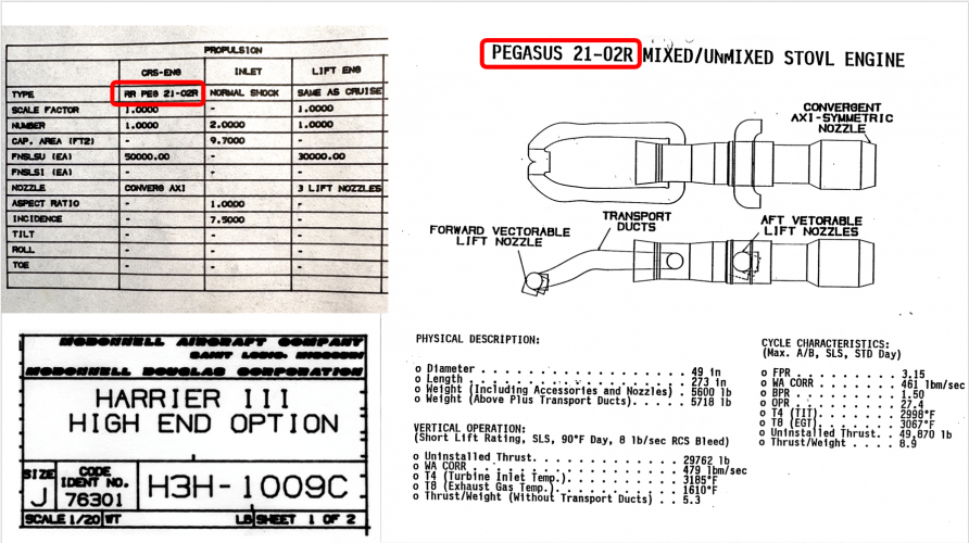
I seriously can't wait to read your book, but it's shown on pre-order at both Penguin and Amazon. Is it available anywhere yet? Also, I'm trying to associate the engine in the Harrier 21 package ("Pegasus 21-02R") with the RB571-10, and I'm having some problems. The H21's only surviving documentation makes a reference to "H3H-1009C" which evolved into a -1011 and then when the BAe unique ideas were folded in, into -1017. The layout drawing for -1009C says that its engine was the Peg 21-02R; the configuration description document for the -1011 lists several changes from the -1009C, one of which is a different engine, RB571-13. I thought that maybe the RB571-10 was RR's number for the Peg 21-02R but they don't overlay very well. Do you know the key dimensions for the 571-10? I can't quite make out the annotations on the preliminary installation drawing you posted and I'd like to do a closer comparison with the ones I have for Peg 21-02R.
 
From what I read 578 was the Pegasus derived engine, the 571 used an EJ200 core. So I can't see "Peg 21-02R' being 571?
578 was definitely the Pegasus core for the anticipated preproduction test machines, with 571 then being intended for production aircraft. But was 578 the same thing as Peg 21-02R? Or was the airframe carrying 578 for demonstration testing in the "H3H-10XX" lineage at all? The -1011 data package says that the engine in 1009C was changed to RB571-13, replacing the 1009C's Peg 21-02R which we know from the detailed 3-view of that aircraft. So to my mind Peg 21-02R has to be RB578 and I guess I'll just extract the dimensions of the engine from that drawing. The only reason I care so much is because the spacing between the front cold nozzle cutout and aft hot nozzle cutout is quite a bit different on the 571-10 drawing and the Peg 21-02R, and the difference in the physical size of the two airplanes trends in exactly the opposite direction from what I would have expected, with the higher-power 571 airplane being smaller than the lower-power 578 one. Of course I could just be totally misreading what I have, so maybe I'll take a break and revisit the whole thing with fresh eyes tomorrow. :)
 
I checked Andrew Dow's book on the Pegasus, but it has nothing on the Pegasus 21 or Rb.578.

What if its actually Pegasus 11-21-02R, derived from the Pegasus 11-21 from the AV-8B? I don't have any proof such an engine existed however.
 
RR named some new engines as Pegasus for marketing rather than technological reasons.

The RB571 core is much hotter than the EJ200 and it is part of a series that evolved from the agreement with P&W in 1986. Essentially, it seems to use the nascent F119 core technology.

There were also some attempts to shoe-horn RB211/Trent cores into a Pegasus so the Peg 21 may be one of those. I have a feeling I have a reference somewhere so will keep digging.

All were 'rubber' engines so amenable to new layouts etc. The data I posted was all I have on the RB.560-10 - the annotations seem to have suffered from earlier photocopying.

My book is not out anywhere until 27 August, but 2.5 weeks is hopefully not too long to wait (it took 7 years overall!).
 
Thanks so much for sharing the Harrier 21 story stever_sl

I nearly guessed it right in the previous threads! Now I have to work out how the engine blockers work :)

https://www.secretprojects.co.uk/threads/mcdonnell-douglas-harrier-iii-high-end-harrier-21.46703/

https://www.secretprojects.co.uk/threads/harrier-21-and-minicas-hanging-on-my-wall-now.51750/
Those look like bbq grill vents(!)...

I was expecting something more like a throttle blade with the air getting tapped off just forward of where the blade met the engine casing.
 
I'm trying to work out how to think about these engines relative to others

In lift mode:

Are the rear nozzles core flow only? Or a mix or core and bypass?

I'd assume front nozzle is bypass flow only from the annulus aft of the fan

Compared to the MDD gas driven lift fan approach then; cooler, lower pressure air is being piped forwards (bigger pipes), but no mass and complexity of the fan. But then beacuse the fan provides some augmentation of lift thrust (greater propulsive efficiency) it needs less air bleed supply to give the same thrust (i.e. smaller pipes). From a physical packaging side then the large, wide radius pipe of RB571 also looks a pain to fit into a supersonic airframe.
 
I'm trying to work out how to think about these engines relative to others

In lift mode:

Are the rear nozzles core flow only?
Yes - the study looked at mixed/mixed engines (conventional/vertical flight modes) and Mixed/Unmixed. the RB571 is the latter, the former is the RB.567.
Or a mix or core and bypass?

I'd assume front nozzle is bypass flow only from the annulus aft of the fan
Yes
Compared to the MDD gas driven lift fan approach then; cooler, lower pressure air is being piped forwards (bigger pipes), but no mass and complexity of the fan. But then beacuse the fan provides some augmentation of lift thrust (greater propulsive efficiency) it needs less air bleed supply to give the same thrust (i.e. smaller pipes). From a physical packaging side then the large, wide radius pipe of RB571 also looks a pain to fit into a supersonic airframe.
Yes, volume was always an issue. The engines were sketched rather than designed, and the installations in UK projects (also sketches really) seem to be very generous in having the pipes go through places you might prefer to have fuel, avionics or a weapons bay.
 
Last edited:
To answer a couple of engine questions, the designation "Pegasus 21-02R" is correct, and I'm guessing that it did in fact borrow the first part of the designation from the 11-21, maybe along the lines of thinking that the Peg 11 was for first-gen Harriers, the 21 was added to show the progression from 1st to 2nd-gen Harriers, so 3rd-gen would keep the 2nd gen "21" and add a dash number to it based on which initial design variant it represented. Or something. Anyway the given designation is what's on the H3H-1009C drawing and in the data package as well.
As far as internal volume being lost to the gas ducting, we never found it to be "a pain to fit into a supersonic airframe" although MDC's GCLF ASTOVL sure did. (Look at all those initials in a row!) The difference is that we didn't have to consider any CTOL variants, or drag along design compromises from years of prior work on ASTOVL, CALF, SSF, etc.
No, we had a purely clean sheet to start with and honestly I don't recall our designers having any major problems finding room for plenty of fuel while creating a low-drag airframe that easily met the CAP requirement of 2 hour loiter and 200 nm with missiles, and a 1.5M dash at altitude as well as 1.1M at sea level. Sure, we had to fit a very large diverter valve to switch the engine gas flow between STOVL and CTOL flight modes, but it was all the way at the back of the airplane, where we weren't likely to need to put fuel tanks anyway due to CG issues. If anything, that extra length helped improve the fineness ratio, which certainly didn't hurt our speed potential. And it gave H21 a huge advantage over ASTOVL, which as I said did in fact find the duct integration to cause major headaches because the lift fan took up so much volume in a forward area where we WOULD have liked to put fuel. (I had the good fortune to work AV-8B, Harrier III, ASTOVL, JAST, and JSF so I got to see a lot of these kinds of design problems.)
 

Attachments

  • 1786387779388.png
    1786387779388.png
    1.6 MB · Views: 101
Last edited by a moderator:
So the majority of the vertical thrust presumably comes from the 2 vectorable nozzles which are further forward, nearer to the CG/CL than if it used a vectorable convergent axisymmetric nozzle like F-35, with the front nozzle forming the third post for balance.
 
So the majority of the vertical thrust presumably comes from the 2 vectorable nozzles which are further forward, nearer to the CG/CL than if it used a vectorable convergent axisymmetric nozzle like F-35, with the front nozzle forming the third post for balance
Says thrust split 0.8:1.0 in the hover so relatively even. The aft nozzles are further forward relative to F135, but the engine aft of the turbine is much longer as well than F135 so there's some odd impacts on CG overall. It's difficult to separate engine from overall airframe balance.

My memory is that 1 fore 2 aft nozzle arrangement was a lot worse for fountain lift enhancement and HGI than 2 fore 1 aft nozzle arrangement.

As far as internal volume being lost to the gas ducting, we never found it to be "a pain to fit into a supersonic airframe" although MDC's GCLF ASTOVL sure did. (Look at all those initials in a row!) The difference is that we didn't have to consider any CTOL variants, or drag along design compromises from years of prior work on ASTOVL, CALF, SSF, etc.
The main difference is then also having to incorporate a large internal payload bay and other design features for LO e.g. convoluted intake duct. Which make a very large impact on max cross sectional area, slenderness and wave drag. It's a lot easier when you can put the weapons on the outside.

Yes, volume was always an issue. The engines were sketched rather than designed, and the installations in UK projects (also sketches really) seem to be very generous in having the pipes go through places you might prefer to have fuel, avionics or a weapons bay.
From looking at the example P.112 variant earlier in this thread with similar engine then it's pretty easy to see the issues.
 
Turbine inlet temperature of 3185 F is 2025 K, way over Peg 11-21 temperatures, or EJ.200.

It's using the same temps and materials as F119, although by 1991 likely RR own tech.
 
My memory is that 1 fore 2 aft nozzle arrangement was a lot worse for fountain lift enhancement and HGI than 2 fore 1 aft nozzle arrangement.


The main difference is then also having to incorporate a large internal payload bay and other design features for LO e.g. convoluted intake duct. Which make a very large impact on max cross sectional area, slenderness and wave drag. It's a lot easier when you can put the weapons on the outside.


From looking at the example P.112 variant earlier in this thread with similar engine then it's pretty easy to see the issues.
Since we weren't stuck with the front nozzles having a fixed location relative to the inlet, like AV-8B did, we had quite a bit of leeway for locating the position of the combined L/R forward centerline nozzle, which let us fine tune the fountain characteristics.
As for skipping internal weapon bays - well, there were darned good reasons involving a LOT of Ops Analysis modeling, but everything along those lines is probably too sensitive to talk about even today. Let's just say that some things are more important than others when you're operating the way the USMC was operating at the time, and given the procurement environment of the early 1990s. We thought then, and I still think today, that we had struck just the right balance for affordable mission effectiveness and survivability.
 
Compared to the F-135, it lacks somewhat in vertical takeoff thrust, 31,000lb to 40,000lb+, but is obviously a lot simpler.
And consequently also much lighter: 5,718lb vs 7,260lb for the F-135-PW-600 with LiftFan system.
Though it is ~2,000lb heavier than a standard Pegasus (11-61 3,960lb dry) - which does negate some of the +6,000lbf vertical thrust improvement the 21-02R offers.
 
I went back and had a look at this. Looks like this then sets up a spanwise jet fountain formation so helping to block near field HGI entrainment from the hotter aft nozzle/s
Exactly! Which is why, if you look at the Lift Improvement Devices drawing, the front dam is so far back, behind the cold nozzle. It just worked out better all-around that way.
 
Had the Harrier 21 project been given the go ahead for production when do you think service entry would have been possible?

One of the drawings is dated 1992. I’m wondering if it could have beaten the Eurofighter Typhoon to service and if it’s performance would have threatened the need for Typhoon?

I like the idea of a Harrier 21 / FOAS fleet :)
 
Are there any GA. drawings of the Low and Medium Harrier III proposals ?, I don't recall seeing them previously ?
 
Those look like bbq grill vents(!)...

I was expecting something more like a throttle blade with the air getting tapped off just forward of where the blade met the engine casing.
Yep, bbq vent style blocker for the forward “cool” flow and my current thinking for the rear hot blocker is a drill chuck style mechanism.

I think you could get both working in unison off a common drive shaft to produce a turn to block mechanism.
 

Similar threads

Back
Top Bottom