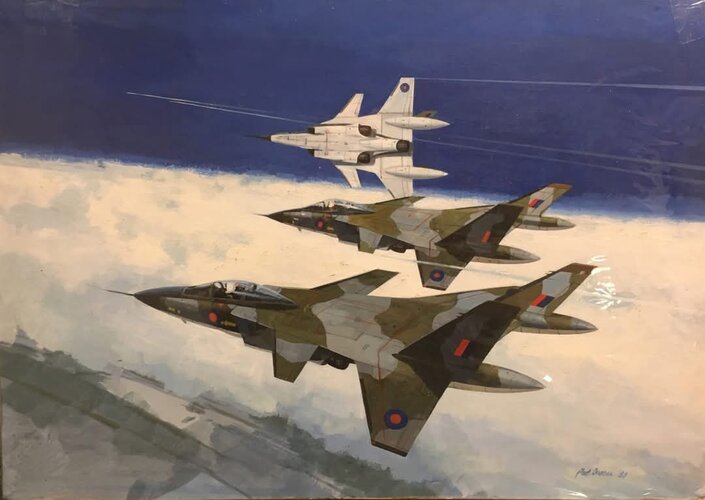
They never were:They weren't shy about how they went after new business either
https://en.wikipedia.org/wiki/Lockheed_bribery_scandals

They never were:They weren't shy about how they went after new business either

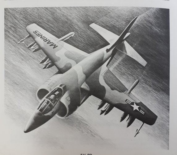
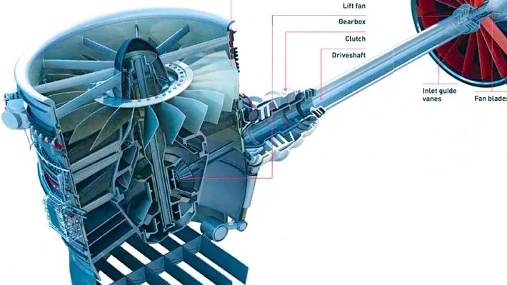
The problem always was that the USMC was adamant about never buying a STOVL fighter/attack airplane that had to have more than one working engine to hover and land safely. Now, of course, they have F-35B, whose lift fan is a lot more complex than people seem to realize. I would love to see the reliability and safety figures on that, as opposed to those for an outright 2-engine design, remembering that it's not just the lift fan itself but the driveshaft and clutch and gearbox whose failure would also lead to catastrophe just as surely as failures in the actual engine.I actually found something along these lines. Mind - it's from a computer game and absolutely fictional, but - it shows how to combine the 4-exhaust layout with internal weapons bay. (sorry for the nuclear blast in the background, that's the only coherent bottom view I could find)
View attachment 758961
View attachment 758959
You just need two engines, and put the bay between them.
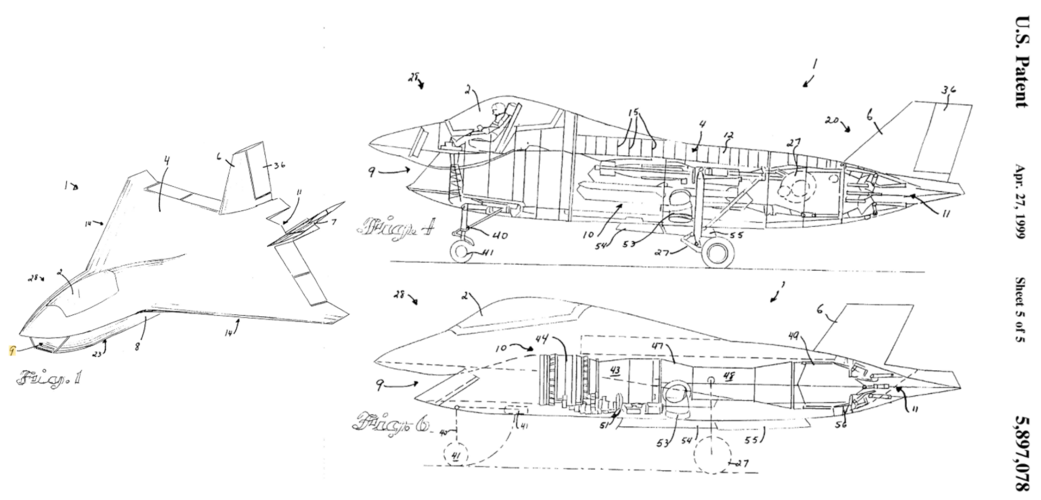
If you mean X-32, several people in Seattle (including Dennis Muilenburg, future CEO of Boeing) patented the configuration and some of us speculated that this patent was the reason they held on to the ugly and unworkable delta-with-backward-inlet layout for so long. That might not be fair, but being able to say that "I thought up that airplane" is a powerful motivator. (We ran into the same kind of thing on another failed program that had a foundational patent with fatal flaws, but that's a whole other story.)Always wondered where Boeing got their idea for the JSF design from. Now I know.
Probably not. The forward nozzles would be in the way of significant blending there. At best, it'd probably be as blended as the XP-67 Moonbat.
And if you want to know all about XP-67, you can read the book that my wife and I wrote on it! Only I'd suggest the e-reader edition rather than a paper copy. On the paper copy the photos and drawings and blueprints are way smaller than we thought they'd be, due to how the publisher arranged the material to fit the format of this general series (which has now been discontinued, by the way.) With the digital edition, though, you can open each illustration and zoom in to get much better detail. Oh, and by the way, we don't get a penny in royalties, it was strictly a work for hire.Probably not. The forward nozzles would be in the way of significant blending there. At best, it'd probably be as blended as the XP-67 Moonbat.
LOL. Sure does!


Funny, I always liked this configuration of early X-32. No idea how it flew, but it looks cutepatented the configuration and some of us speculated that this patent was the reason they held on to the ugly and unworkable delta-with-backward-inlet layout for so long.
I still fondly recall that the X-32 was nicknamed 'Monica' not long after the Clinton Oval Office turbulent flow blue dress incident...Funny, I always liked this configuration of early X-32. No idea how it flew, but it looks cute
I don't think either of them was (ex) Navy, and as for inhaling, apart from pure ambient air, any other matter is pretty much never a good idea...as in The "Sailor Inhaler"?
Yes, but there are always accidents of some poor Sailor standing up too close to the inlets and getting taken for a ride.I don't think either of them was (ex) Navy, and as for inhaling, apart from pure ambient air, any other matter is pretty much never a good idea...
I *honestly* did not have that aspect in mind, but well, then let's consider grids in front of engine air intakes for *every* design (civilian, commercial, military, experimental, whatever) going forward due to FOD risk. I have no skin in this game, so I'm genuinely curious where this discussion might go, but then again, I realize this is definitely off topic, so please, moderators, deal with the mess I just made as you see fit.Yes, but there are always accidents of some poor Sailor standing up too close to the inlets and getting taken for a ride.
If the sailor is lucky they drop a flashlight or their helmet comes loose and takes out the engine before they get to the fan. But now that I think about it, the Radar Blocker grid in the X-32's mouth would hopefully stop the sailor from going into the fan.
I don't think either of them was (ex) Navy, and as for inhaling, apart from pure ambient air, any other matter is pretty much never a good idea...

I meant the X-32B. What were you all thinking of?as in The "Sailor Inhaler"?
Yes, 53 is the forward ("cold" flow) vectorable nozzle on each side of the fuselage. And it apparently flew very well despite its appearance, according to the test pilots. I never saw the Government's official comparison though.Funny, I always liked this configuration of early X-32. No idea how it flew, but it looks cute
What's that marked by 53 there? Looks like rotating exhaust.
There was this image around the thread (I can't find the exact post, but I certainly downloaded it from somewhere around here):I always felt P.1216 was the logical end of P.1154 developments.
No, the weapon bays would need to be out of the PCB flow. It might work if the bays were between the canards and the main.There was this image around the thread (I can't find the exact post, but I certainly downloaded it from somewhere around here):
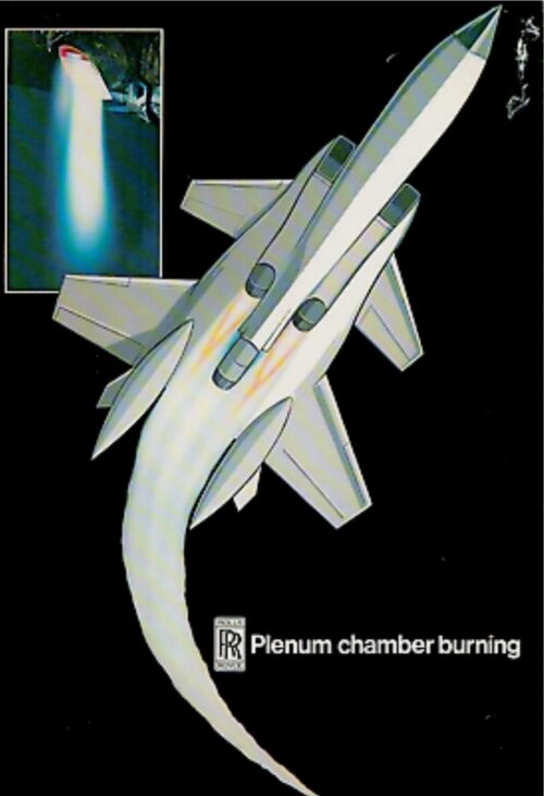
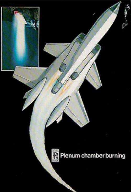
That shows (probably) the most "modern" configuration of the aircraft with this engine. I suppose the weapon bays are located a bit after the secondary nozzles and open (mostly) sideways. Could it work at all? Would they have to be extended? Especially with what you say about PCB temperatures? Is it landing gear in those tail consoles? Or fuel? And what is known about this image, was it just a Rolls Royce illustration, or one of existing concepts?
That's what I meant - the secondary nozzles being the forward ones.It might work if the bays were between the canards and the main.
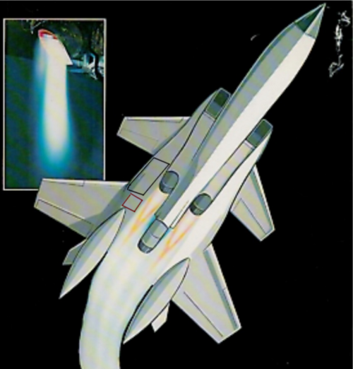


It is not related at all. Just PR artwork to show three nozzles by Rolls, with pods in just the right place to be burned off, the very thing the P1216 was to avoid. It's a shame Frank Mason put it in his Hawker Putnam. Complete mistake.Wait, is that a variant or an evolution of P.1216 ?
I always felt this would make better CTOL design than a STOVL one.SPECULATIVE Rolls Royce PCB. design ?
... https://www.facebook.com/share/p/1YgZdZFzYo/
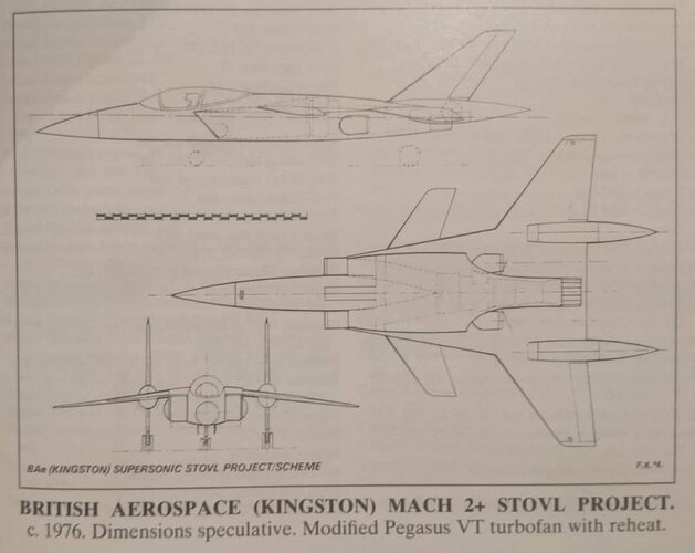
Straight-through Pegasus would have been roughly 28-30klbs of thrust at military power. Then you can stick an afterburner on it and kick it up to probably 55klbs.I always felt this would make better CTOL design than a STOVL one.
Which is to say a single fixed nozzle out the back, rather than the three poster vectored nozzles.
More like 45. F135 is 28/45; a multiple of 1.5-1.6 for afterburner is pretty standard and 55 would be close to double.Straight-through Pegasus would have been roughly 28-30klbs of thrust at military power. Then you can stick an afterburner on it and kick it up to probably 55klbs.

Reduced size, surely.An example straight through Pegasus is RB.431 with ~16klbf dry and 28klbf wet. A later Pegasus variant probably higher thrust with greater mass flow and turbine and reheat temperatures.
Earlier Pegasus variant than Mk 107, but mostly the thrust increases in VTOL don't translate to a typical max dry rating e.g. overspeeding the fan, water injection. A more typical max dry rating for the later Pegasus is still around 16klbf for Up and Away flight.Reduced size, surely.
Automotive exhaust systems disagree about that.The bends in the exhausts don't make a large impact to efficiency/thrust as the pressure gradient is favourable here (+vanes).

Funny, I always liked this configuration of early X-32. No idea how it flew, but it looks cute
And it apparently flew very well despite its appearance, according to the test pilots. I never saw the Government's official comparison though.
The aft fuselage was lengthened and horizontal tails added well before the competition downselect. It was the configuration that we did performance analysis on, and cost, risk, signature, vulnerability, everything. I started on the program about a month after the Boeing/MDC merger and was with it all the way to the catastrophic endgame. It was really hard to get Seattle to accept the horizontal tails but it had to be done, and done relatively quickly, for the reason you mention on the Navy version, among other things. I don't know the exact date when the tails became part of the official configuration, but maybe somebody still has the program history/evolution timeline chart that was put together for one of the managers. If memory serves, the tailless delta configuration was Model 372 which changed to Model 374 once the tails were added, if that helps.The USN differed there, as their evaluation said the delta-design wouldn't do well in the turbulent air at the aft end of the flight deck (same thing that helped end the A-12 program).
That is why Boeing proposed the "lengthened aft fuselage with horizontal stabilizers added" version shortly before Lockheed was granted the win.
Actually this paper gives the context for a number of changes that were made, including lengthening the fuselage and adding horizontal tails. It dates the studies to 1998, and a figure implies that their incorporation became official very early in 1999. Downselect was in late 2001.The aft fuselage was lengthened and horizontal tails added well before the competition downselect. It was the configuration that we did performance analysis on, and cost, risk, signature, vulnerability, everything. I started on the program about a month after the Boeing/MDC merger and was with it all the way to the catastrophic endgame. It was really hard to get Seattle to accept the horizontal tails but it had to be done, and done relatively quickly, for the reason you mention on the Navy version, among other things. I don't know the exact date when the tails became part of the official configuration, but maybe somebody still has the program history/evolution timeline chart that was put together for one of the managers. If memory serves, the tailless delta configuration was Model 372 which changed to Model 374 once the tails were added, if that helps.
I really wish someone made a model of the "EMD" version... I still have a couple of the Italeri X-32 kits lurking around.The aft fuselage was lengthened and horizontal tails added well before the competition downselect. It was the configuration that we did performance analysis on, and cost, risk, signature, vulnerability, everything. I started on the program about a month after the Boeing/MDC merger and was with it all the way to the catastrophic endgame. It was really hard to get Seattle to accept the horizontal tails but it had to be done, and done relatively quickly, for the reason you mention on the Navy version, among other things. I don't know the exact date when the tails became part of the official configuration, but maybe somebody still has the program history/evolution timeline chart that was put together for one of the managers. If memory serves, the tailless delta configuration was Model 372 which changed to Model 374 once the tails were added, if that helps.
Air Signatures did a 1/72nd scale diecast X-32A (#99138) that, while having all the drawback of metal diecast - deep panel lines, bosses for screws, etc - looks like the X-32A OML unlike the Italeri kit which is marginal even when viewed from six feet. As far as EMD, you are out of luck unless you can pick up a Pacmin solid on evilBay.I really wish someone made a model of the "EMD" version... I still have a couple of the Italeri X-32 kits lurking around.


camel hump does nothing good to the looks of the Harrier.Flight International, 18 October 1980