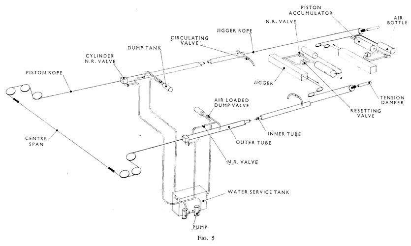
DA 2 Arresting Gear (FIG. 5)
The basic design for the new carrier arresting gear has been retained. The Staff Requirement for this design is to arrest aircraft in the weight range 15,000-40,000 Ib from engaging speeds not less than 110 kts for the lower weight aircraft and not less than 125 kts for the upper weight, without exceeding a retardation of 4-2 g. From ship and equipment considerations the arrest must be completed within a run-out distance of 270 ft, with a deck-edge sheave spacing of 100 ft and with a limiting factor of safety (FOS) of not less than 2 on all arresting gear components. The arresting gear designed and being developed to meet these requirements is the DA2. The essential features of DA2 are:
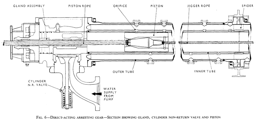
(a) The Energy Absorbing Unit (FIG. 6)
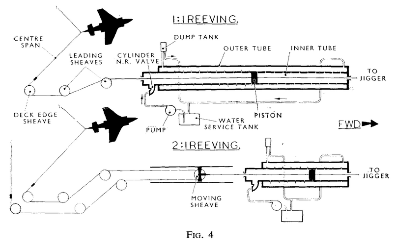
This unit is an inner tube of 5% in. bore contained in a 10 in. bore outer tube and arranged in 2 lines approx. 230 ft long. Along each inner tube are approximately 200 orifices of $ in. diameter. A piston, 12 in. long, connected to the arresting gear rope system runs in each inner tube. Each tube length is anchored at one end only. The tube length is aligned and supported to within a limit of f 0.1 in. over 220 ft and is free to move axially to allow for expansion of the unit or relative ship/unit movement from other causes. The inner and outer tubes are kept full of fresh water by pumps. When the rope system is engaged by the aircraft the pistons are pulled along the inner tubes expelling and circulating the water ahead of each piston through the orifices into the outer tubes and back into the inner tube behind the pistons. Pressures of up to 3,000 lb/sq in. are generated in the inner tubes. Pressures in the outer tubes are controlled to 600 lb/sq in. by air loaded relief valves. As the piston speed decreases during the arrest so does the orifice area ahead of the piston and a reasonably constant pressure and therefore aircraft retardation, is maintained throughout the arrest. By careful design of the orifice programme the gear is capable of arresting a wide range of aircraft weights and speeds and no adjustment of the gear for different aircraft weights and speeds in the specified range is necessary or fitted. The inner and outer tubes are made up from 12 ft and 8 ft lengths as required to match the spacing of the ship's structure. Inner and outer tubes are solid drawn from EN26 and mild steel BS 806-B respectively.