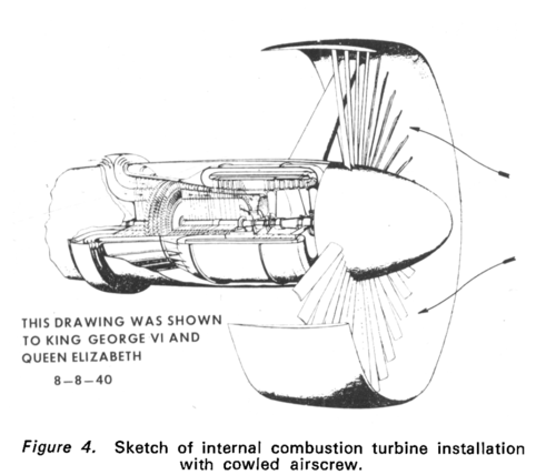
The brilliant foresight and inventiveness of A. A. Griffith is illustrated in Fig. 4. This is a drawing of his cowled airscrew project dated 1940. The gas generator consisted of a series of independent turbine/compressor stages rotating in opposite directions at their own selected speeds. It became known as the 'contraflow' unit and was the first gas turbine element built at Rolls-Royce, Derby. Although it was under development for several years it was never a practical success, mainly due to the gas leakage between the turbine and compressor annular passages. It would not run self-sustained and had to be pressurised from an independent source. For the younger engineers at the firm this was an important lesson—Griffith's turbofan concept was theoretically sound, but it could only be realised in practice in a design of engine in which the compression and expansion processes were efficient.


.jpg")