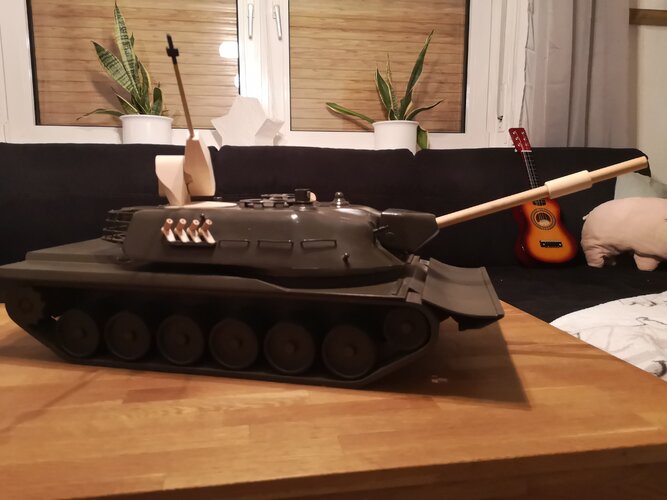
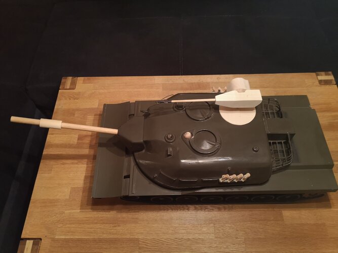
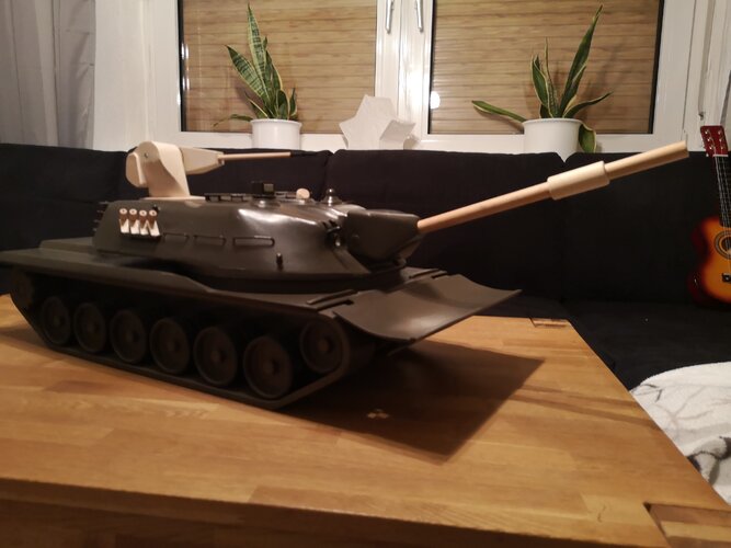
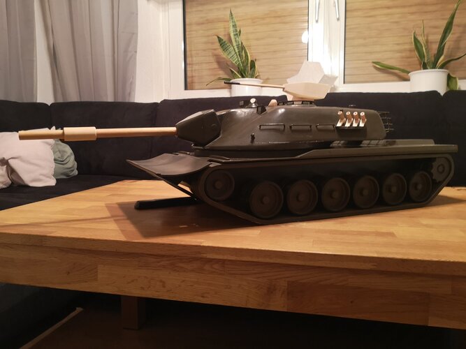
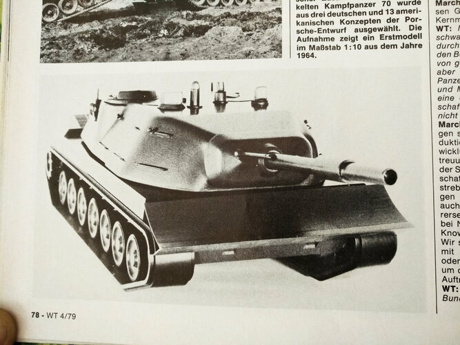
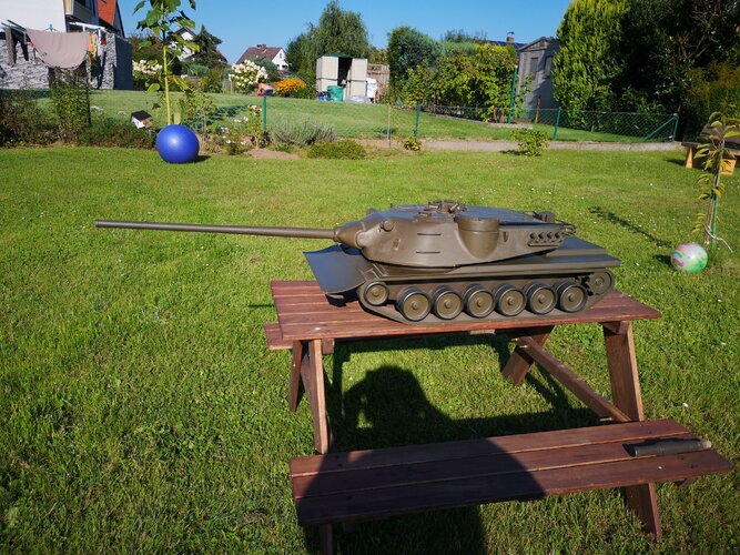
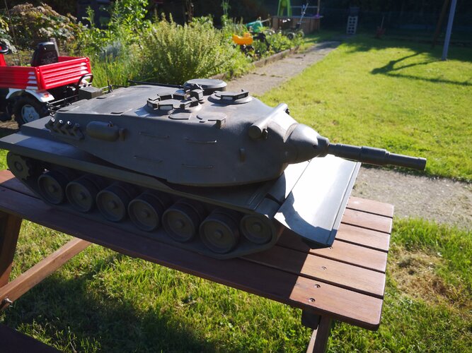
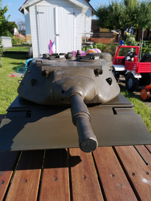
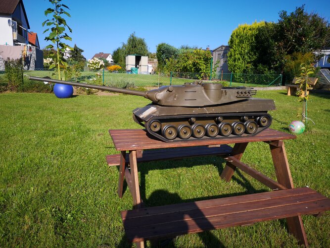
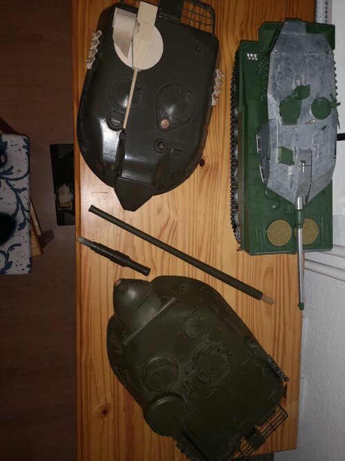
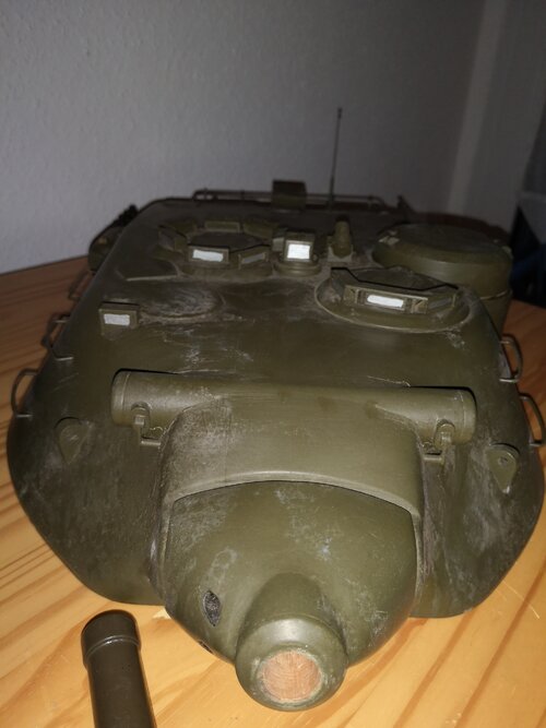
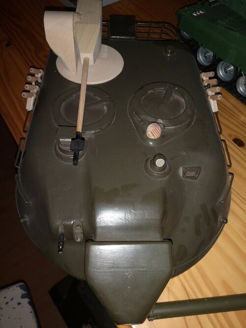
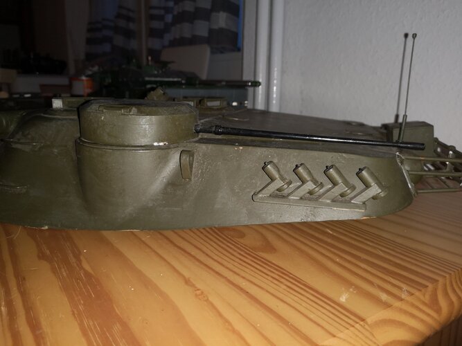
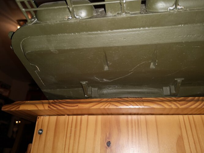
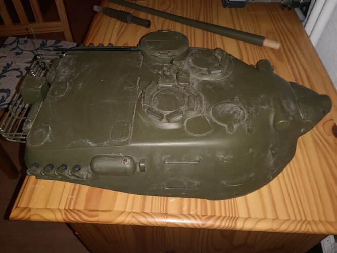
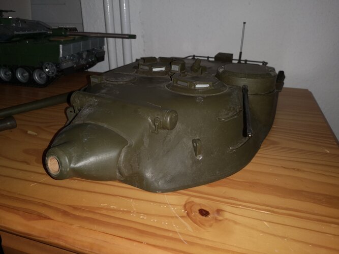
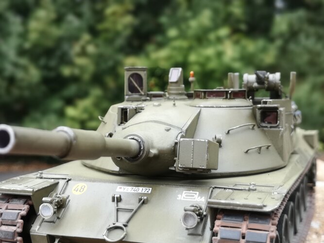
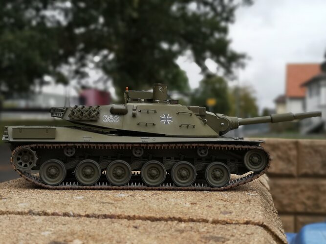
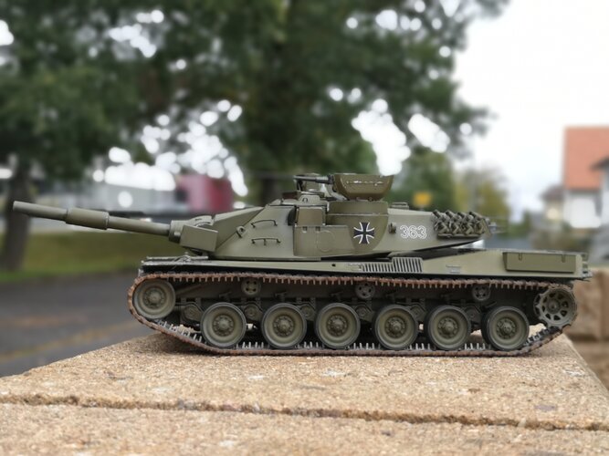
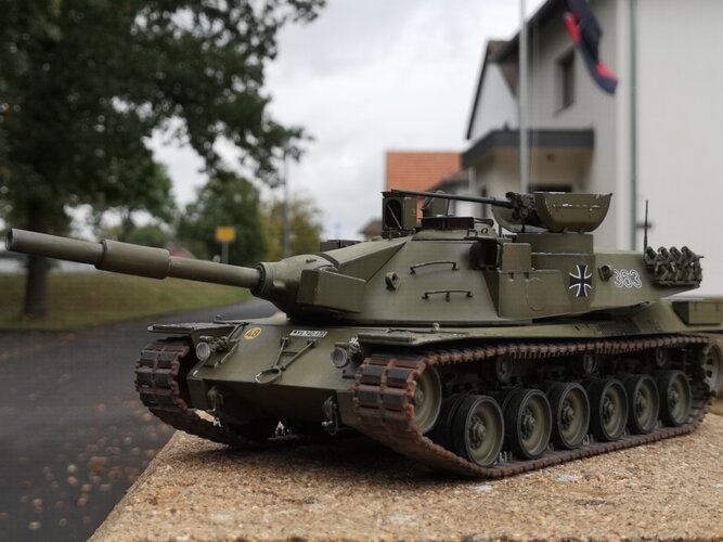
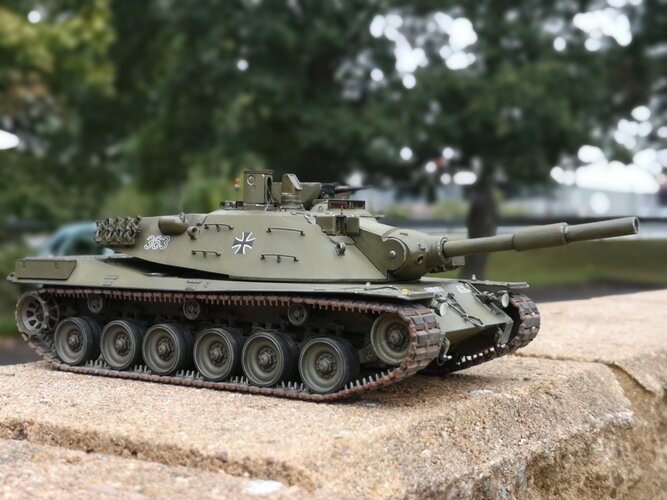
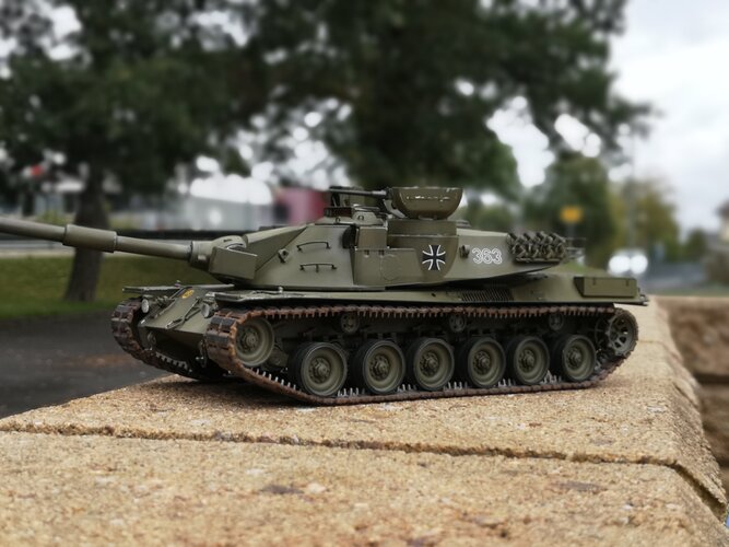
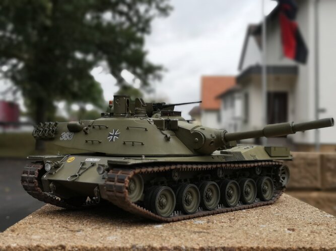
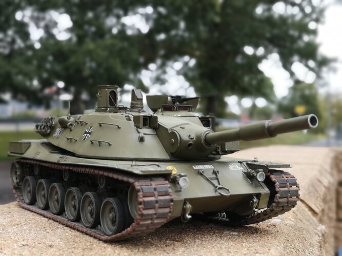
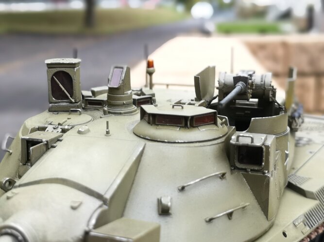
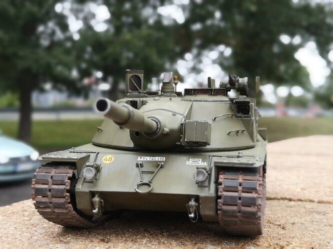
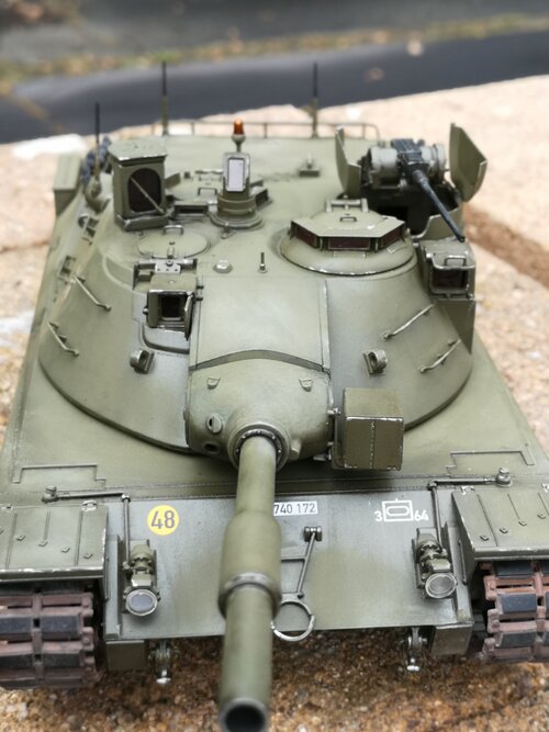
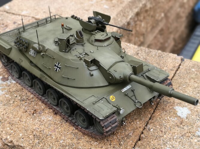
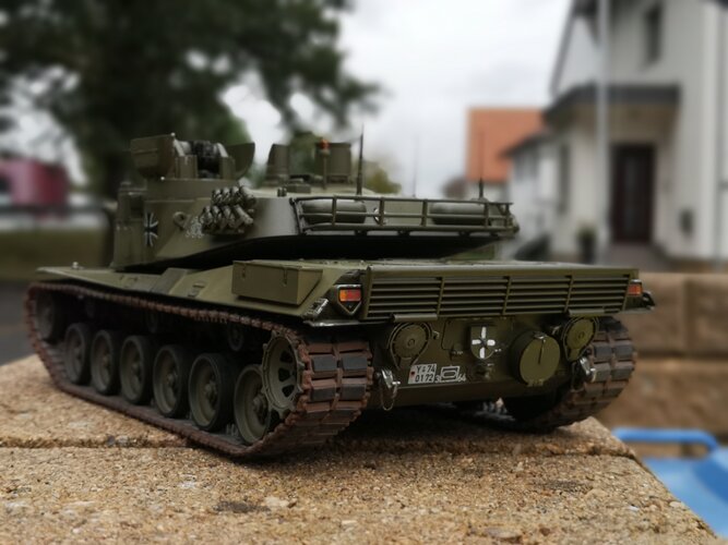
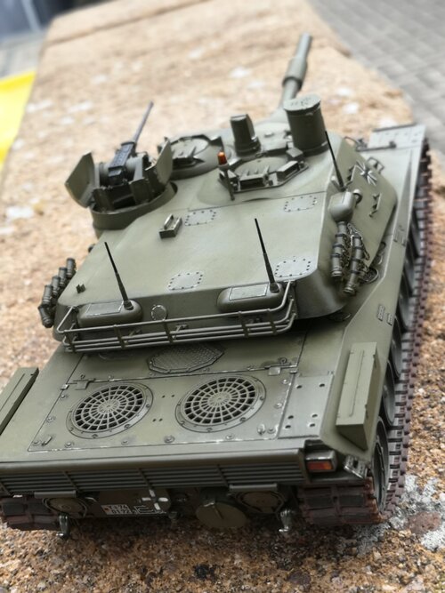
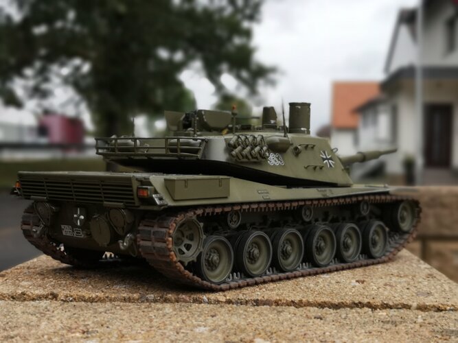
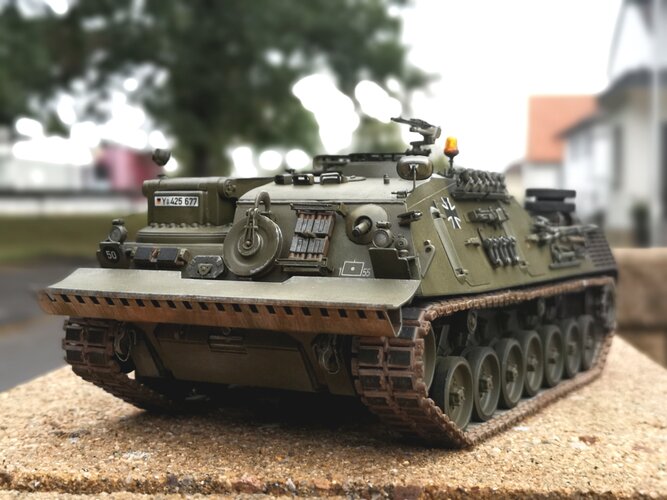
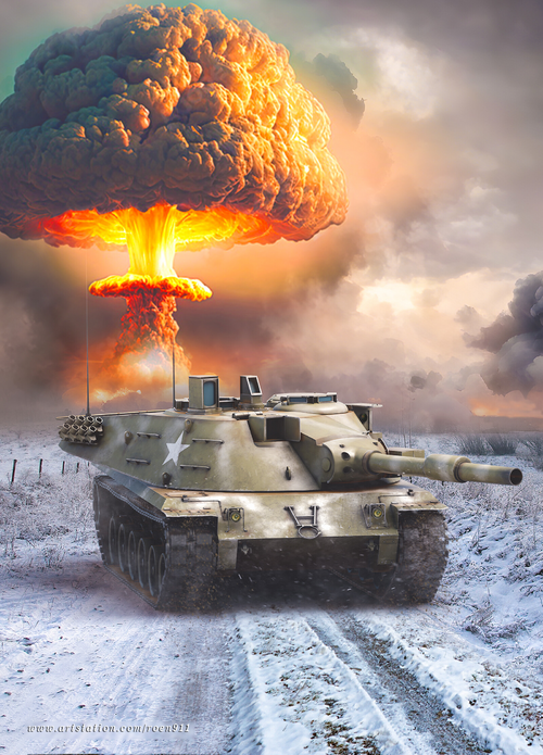
My dream has already been fulfilled with this Kampfpanzer 70, but I would be really happy to get the Borgward tank or one of the double-barreled casemate tanks one day! The Borgward Panzer :D

@ Uk 75 I'll look tomorrow at the photo album of my father who had photographed the PT 11 Leopard 2 in the maneuver in the 70s!
 
Hello dear tank friends! I once had the model restored by a carpenter friend! I hope the restoration went well!

Greetings from Frielendorf -Germany
 

Attachments

  • IMG_20210225_191056.jpg
    IMG_20210225_191056.jpg
    2.3 MB · Views: 428
  • IMG_20210225_191003.jpg
    IMG_20210225_191003.jpg
    2.7 MB · Views: 374
  • IMG_20210225_191039.jpg
    IMG_20210225_191039.jpg
    2.6 MB · Views: 345
  • IMG_20210225_191026.jpg
    IMG_20210225_191026.jpg
    2.6 MB · Views: 356
Really nice model, but is the gun barrel seems long for Shillelagh or is it for 120mm smoothbore?
 
Looks good. You just now need to match the colour and the tone of original paint.
 
The two guns were not entirely the same, I am not aware that the M551 or M60A2 ever used the APFSDS. This round would eventually be used (slightly altered) in the 105mm M68 gun as M735.
 
Hi all, sorry to bother, but I would be curious to know what other countries contributed to the MBT-70 project besides Germany and USA? I know for example that italy participated in the development of an autoloader for the XM-150, so were there other countries participating?
 
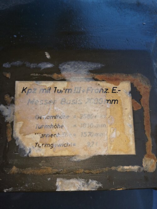
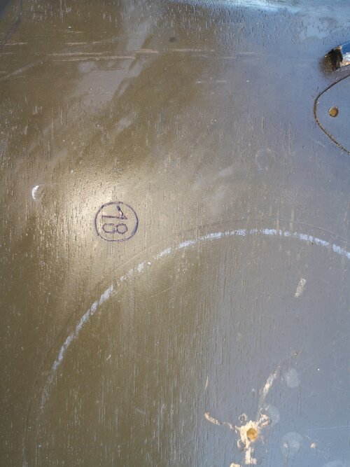
Hello on Friday, I just got something that is a mystery to me. On the one hand a turret of the pre-series battle tank 70 with two different Barrels and a Leopard 1 hull which was used for a "project" like on the pasted over original sign! On the pictures you can see the 18 of the chassi and the turret. But actually the turret is pre-series battle tank 70. I once photographed both options. According to the source from which I got the vehicle, the "Kampfpanzer 70" program was looked to to minimize costs in the 1960s.

Here are the pictures of the 3 in 1 prototype

Gretings from Frielendorf - Germany :)
 

Attachments

  • IMG_20210903_170306.jpg
    IMG_20210903_170306.jpg
    6.8 MB · Views: 316
  • IMG_20210903_170332.jpg
    IMG_20210903_170332.jpg
    3.8 MB · Views: 292
  • IMG_20210903_170338.jpg
    IMG_20210903_170338.jpg
    3.4 MB · Views: 253
  • IMG_20210903_170544.jpg
    IMG_20210903_170544.jpg
    6.1 MB · Views: 258
  • IMG_20210903_171246.jpg
    IMG_20210903_171246.jpg
    3.1 MB · Views: 227
  • IMG_20210903_171613.jpg
    IMG_20210903_171613.jpg
    4.1 MB · Views: 199
Last edited:
That label say (on pic img_20210903)

KPZ mit Turm III+Franz. E.-
Messer Basis 7000 mm (? nicht deutlich zu sehen)
Gesamthöhe 2580 mm
Turmhöhe 1010 mm
Wannenhöhe 1570 mm
Turmgewicht 9,7 t

Combat tank with turret III+Franz.E.-
measurement base ? 7000 mm (? unclear to see)
Total height 2580 mm
Turret height 1010 mm
Armored hull height 1570 mm
Turret weight 9.7 t
 
Last edited:
That label say (on pic img_20210903)

KPZ mit Turm III+Franz. E.-
Messe Basis 7000 mm (? nicht deutlich zu sehen)
Gesamthöhe 2580 mm
Turmhöhe 1010 mm
Wannenhöhe 1570 mm
Turmgewicht 9,7 t

Combat tank with turret III+Franz.E.-
Fair base ? 7000 mm (? unclear to see)
Total height 2580 mm
Turret height 1010 mm
Armored hull height 1570 mm
Turret weight 9.7 t
E. Messer is abbreviation of Entfernungsmesser, that is rangefinder in German. This optical(coincidence/stereoscopic) rangefinder has a baseline length of 2m.
 
Here are a few comparative pictures of the MBT 70 turrets with all options of the armament
 

Attachments

  • IMG_20210903_201946.jpg
    IMG_20210903_201946.jpg
    3.2 MB · Views: 189
  • IMG_20210903_201959.jpg
    IMG_20210903_201959.jpg
    2.9 MB · Views: 174
  • IMG_20210903_202008.jpg
    IMG_20210903_202008.jpg
    3.1 MB · Views: 143
  • IMG_20210903_202023.jpg
    IMG_20210903_202023.jpg
    2.7 MB · Views: 130
  • IMG_20210903_202038.jpg
    IMG_20210903_202038.jpg
    2.6 MB · Views: 131
  • IMG_20210903_202050.jpg
    IMG_20210903_202050.jpg
    2.7 MB · Views: 142
  • IMG_20210903_202103.jpg
    IMG_20210903_202103.jpg
    2.7 MB · Views: 143
  • IMG_20210903_202116.jpg
    IMG_20210903_202116.jpg
    2.9 MB · Views: 169
E. Messer is abbreviation of Entfernungsmesser, that is rangefinder in German. This optical(coincidence/stereoscopic) rangefinder has a baseline length of 2m.
Then it means

KPZ mit Turm III+Franz. E.-Messer Basis 2000 mm

Franz. any chance that stand for Französisch (french) ?
 
That label say (on pic img_20210903)

KPZ mit Turm III+Franz. E.-
Messe Basis 7000 mm (? nicht deutlich zu sehen)
Gesamthöhe 2580 mm
Turmhöhe 1010 mm
Wannenhöhe 1570 mm
Turmgewicht 9,7 t

Combat tank with turret III+Franz.E.-
Fair base ? 7000 mm (? unclear to see)
Total height 2580 mm
Turret height 1010 mm
Armored hull height 1570 mm
Turret weight 9.7 t
Franz. could mean Französisch, that's to say this rangefinder is French made M208 rangefinder, have a baseline length exactly 2.00m. And the tank gun barrel without fume extractor, must be a French CN105F1, or Fhench experimental smoothbore 120mm tank gun.
 
Last edited:
Franz. could mean Französisch, that's to say this rangefinder is French made M208 rangefinder, have a baseline length exactly 2.00m. And the tank gun barrel without fume extractor, must be a French CN105F1, or Fhench experimental smoothbore 120mm tank gun.
this is odd
I don't known of any French participation into Kampfpanzer 70 / MBT70
either for studies Keiler or Eber what became Leopard 2 tank
although there were French German cooperation for Leopard 1 tank development.
but those were from 1957 until 1963.
 
Bought a cheap paperback copy of the Hunnicutt book on Abrams which covers MBT70
Here, hopefully not braking copyright, are the three MBT70 variants as small snaps
RV XM742 recovery tank
AVLB XM743/4 bridge tank
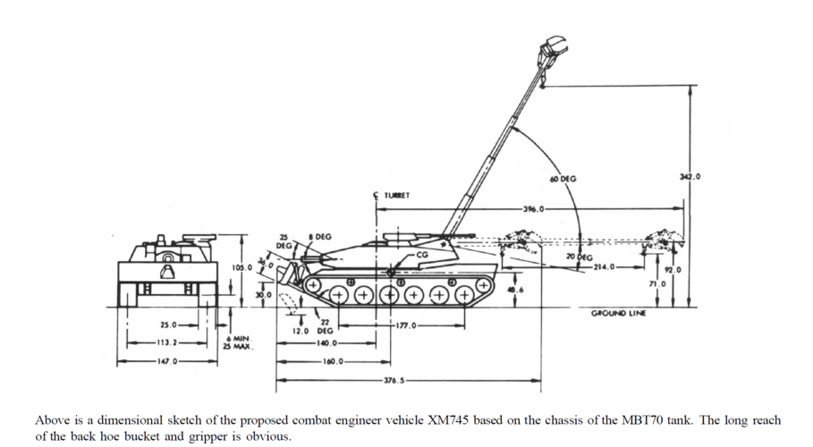
CEV XM745 engineer tank
Is there any chance you could get a clearer picture of the XM745? As I am unable to read the caption below it
 
Bought a cheap paperback copy of the Hunnicutt book on Abrams which covers MBT70
Here, hopefully not braking copyright, are the three MBT70 variants as small snaps
RV XM742 recovery tank
AVLB XM743/4 bridge tank
CEV XM745 engineer tank
Is there any chance you could get a clearer picture of the XM745? As I am unable to read the caption below it


XM745.png

Alternative CEV.png

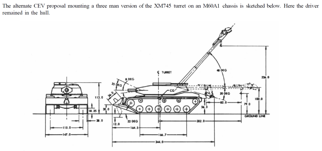
During the MBT70 development program, several companion vehicles were proposed based on the same chassis. One of these was designated as the CEV XM745. A concept drawing, layout number LK 1041 dated 28 August 1967, depicted a vehicle on the MBT70 chassis armed with the 165mm demolition gun mounted in a four man turret. However, some reports refer to the installation of a 152mm demolition gun in the XM745. The crew consisted of the driver, commander, gunner, and loader. The latter also manned a 25mm automatic gun mounted on top of his vision cupola. This weapon had a 360 degree traverse and an elevation range of +70 to -18 degrees. Other secondary armament consisted of a 7.62mm machine gun coaxial with the demolition gun.

A 60,000 pound capacity tow winch was located in the turret bustle below the mount for the 20,000 pound capacity boom assembly. The latter could be extended from 144 inches to approximately 360 inches and it was fitted with a back hoe bucket and gripper as well as a lifting hook. An hydraulically operated bulldozer fitted with a ram was installed on the front of the vehicle.

The CEV was powered by the AVCR-1100 engine using a General Motors Allison XHM-1500 transmission. As an alternate CEV for use with the MBT70, it was proposed to install a three man turret with similar equipment on the chassis of the M60A1 tank. In this case, the driver remained in the hull. After the cancellation of the MBT70 and XM803 programs, the CEV role continued to be performed by the M728 based on the M60A1 tank.

From Hunnicutt, Abrams - A History of the American Main Battle Tank
 
Hi, here my 1:35 scale mbt model

Greetings from Frielendorf / Germany
 

Attachments

  • IMG_20220925_143115.jpg
    IMG_20220925_143115.jpg
    4.2 MB · Views: 135
  • IMG_20220925_142908.jpg
    IMG_20220925_142908.jpg
    4.8 MB · Views: 132
  • IMG_20220925_142926.jpg
    IMG_20220925_142926.jpg
    4.8 MB · Views: 120
  • IMG_20220925_142957.jpg
    IMG_20220925_142957.jpg
    1.8 MB · Views: 112
  • IMG_20220925_142748.jpg
    IMG_20220925_142748.jpg
    5.1 MB · Views: 109
  • IMG_20220925_143004.jpg
    IMG_20220925_143004.jpg
    4.9 MB · Views: 102
  • IMG_20220925_143020.jpg
    IMG_20220925_143020.jpg
    4.6 MB · Views: 98
  • IMG_20220925_142759.jpg
    IMG_20220925_142759.jpg
    4.8 MB · Views: 97
  • IMG_20220925_143035.jpg
    IMG_20220925_143035.jpg
    4 MB · Views: 94
  • IMG_20220925_142814.jpg
    IMG_20220925_142814.jpg
    4.6 MB · Views: 96
  • IMG_20220925_143046.jpg
    IMG_20220925_143046.jpg
    4.6 MB · Views: 109
  • IMG_20220925_143054.jpg
    IMG_20220925_143054.jpg
    5.3 MB · Views: 112
  • IMG_20220925_142842.jpg
    IMG_20220925_142842.jpg
    4.6 MB · Views: 105
  • IMG_20220925_143102.jpg
    IMG_20220925_143102.jpg
    5 MB · Views: 90
  • IMG_20220925_142855.jpg
    IMG_20220925_142855.jpg
    4.7 MB · Views: 100
  • IMG_20220920_093540.jpg
    IMG_20220920_093540.jpg
    2 MB · Views: 252
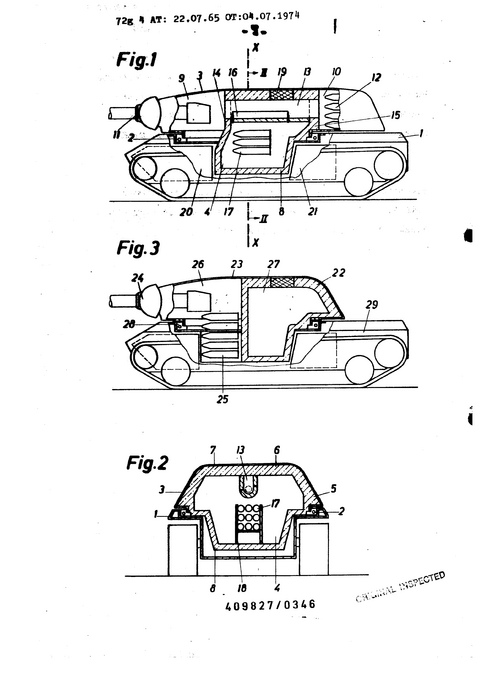
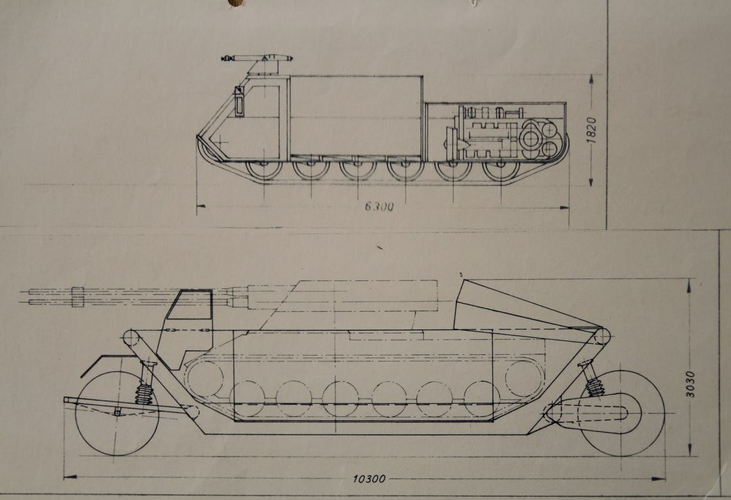
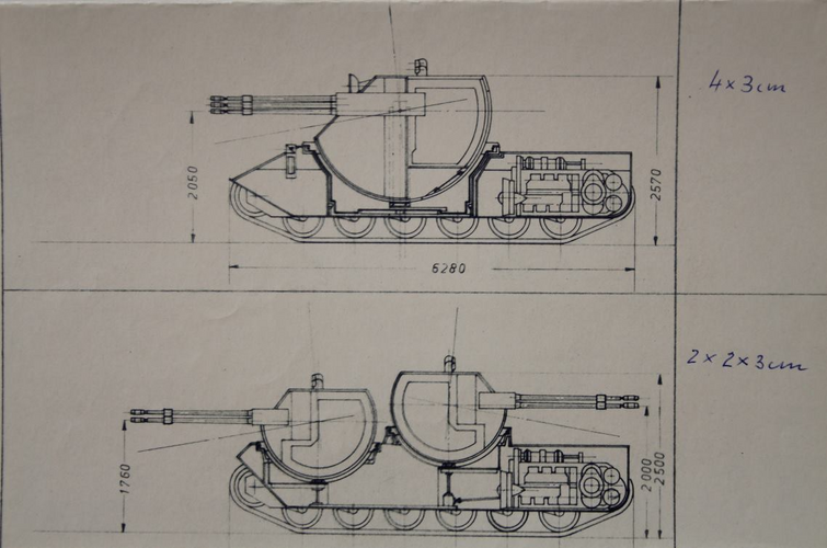
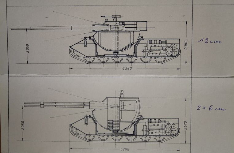
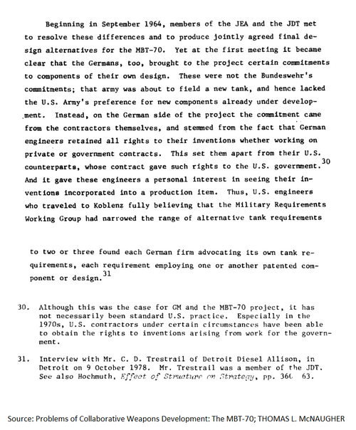
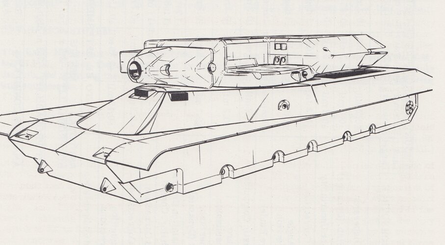
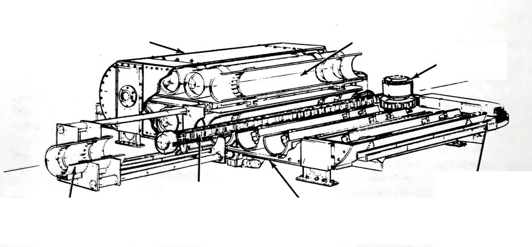
Came across this little tidbit of information, thought it was very interesting how this could have affected MBT-70's divergent development of layouts and designs. Speaking of which, Ed Francis was kind enough to share these with me recently.
 

Attachments

  • Kampfpanzer 70 AA Variant Carrier.png
    Kampfpanzer 70 AA Variant Carrier.png
    600.8 KB · Views: 282
  • Kampfpanzer 70 AA Variants.png
    Kampfpanzer 70 AA Variants.png
    641 KB · Views: 279
  • KPz.70 3 Axis Variant.png
    KPz.70 3 Axis Variant.png
    490 KB · Views: 278
  • KPz.70 3 Axis Variant Drawing.png
    KPz.70 3 Axis Variant Drawing.png
    176.8 KB · Views: 280
  • Kampfpanzer 70 Patent Technology.png
    Kampfpanzer 70 Patent Technology.png
    201.9 KB · Views: 271
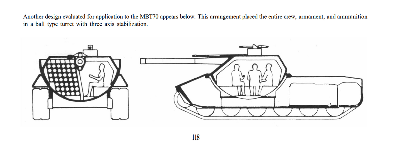
Came across this little tidbit of information, thought it was very interesting how this could have affected MBT-70's divergent development of layouts and designs.
Maybe these designs are from Rheinstahl?


Rheinstahl Hanomag Kampfpanzer 07 RH

Rheinstahl 3-achsig stabilisierter Turm https://www.secretprojects.co.uk/th...-3-achs-stabilisiertem-turm.33488/post-387370

Rheinstahl Kugelturm
https://www.secretprojects.co.uk/threads/german-casemate-tanks.820/post-619035
 

Attachments

  • 1721410577489.jpeg
    1721410577489.jpeg
    521.9 KB · Views: 207
  • 1721410552201.jpeg
    1721410552201.jpeg
    309.7 KB · Views: 182
  • 1721410537398.jpeg
    1721410537398.jpeg
    518.3 KB · Views: 174
  • 1721410524487.jpeg
    1721410524487.jpeg
    644.3 KB · Views: 205
  • 1721410504791.jpeg
    1721410504791.jpeg
    582.9 KB · Views: 241
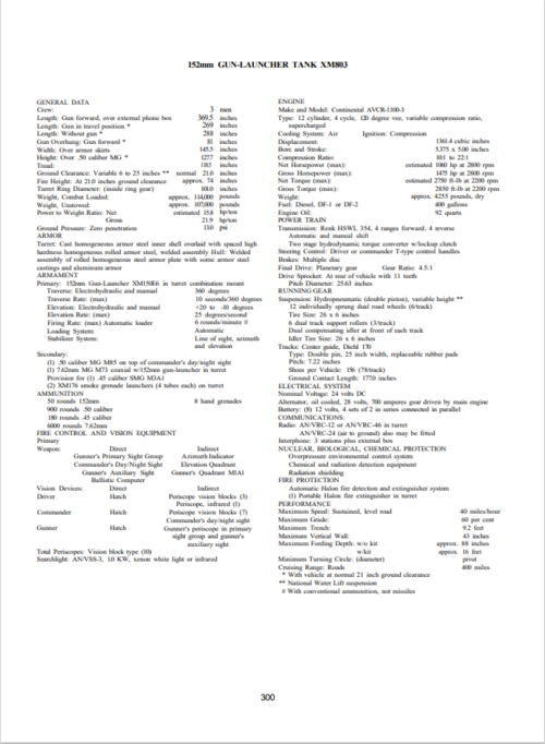
I've been trying to dig up more information on the MBT-70 a bit lately after coming across a few nice models of it. Did the actual MBT-70 and not the revised XM803 ever get a proper "XM" designation?

I've stumbled across a lot of claims online that I can't find much else about. One describing the anti-radiation liner as more of a "foam" than a solid liner and claiming that it required a substantial thickness which restricted how much armor could be included. I'm left wondering what specific threats the spaced armor layout was intended to defeat since an air gap a few inches wide wouldn't do much to affect the better HEAT projectiles introduced by the 1960s. Wouldn't a layer of the fused silica armor the US had been toying with ever since the T95 be much better for that purpose than mere spacing?
 
Was browsing through Hunnicutt when I noticed one of the Rex concepts from 1955;

1765666561337.png

Which notably has the driver in the turret similar to the MBT-70. Was there any testing done of that layout before the MBT-70? (I'm about 99% sure the T95 had a 'conventional' driver position.)
 
EDIT- have now done what I should have done before, and read through the relevant sections of the Hunnicutt book....

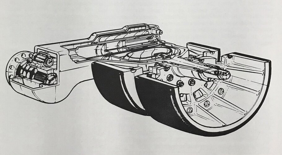
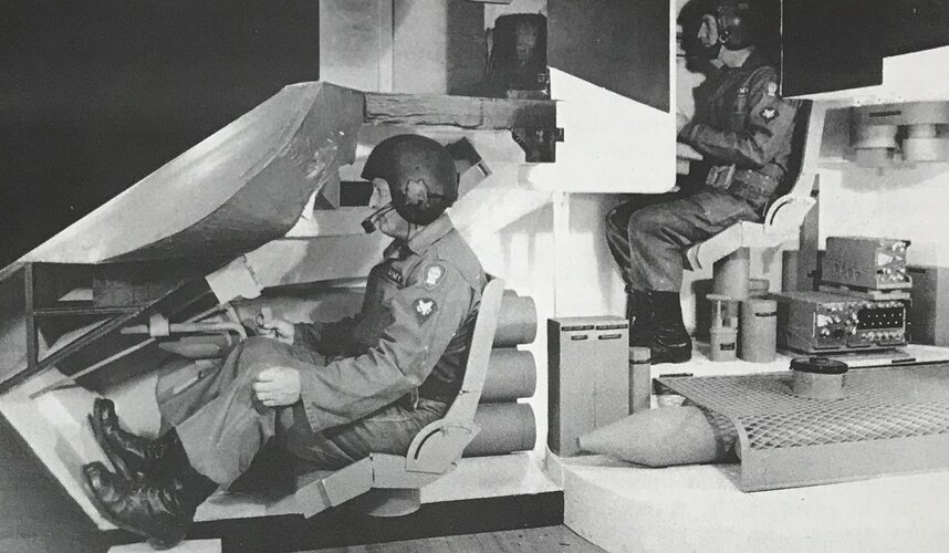
Don't forget, the MBT-70 was designed to operate on a nuclear battlefield, so NBC protection for the crew was essential.
By placing all the crew in the turret, this could be a much easier task, than if the driver was seated separately in the hull.
From Hunnicutt's 'Abrams', p.120 :-
"The entire crew was located in the turret...with this arrangement the turret could be controlled environmentally for protection against chemical and biological airborne contaminants..."
and from p.142 :-
[speaking about measures to reduce the tanks' weight in order to meet the German specification] "It was noted that some weight reduction could be achieved by eliminating the radiation shielding, but this approach raised new objections. One of the reasons for the selection of the driver-in-turret arrangement was the ease with which such shielding could be provided for the entire crew located in such close quarters. If this protection were no longer a requirement, perhaps a complete re-design should be considered."


cheers,
Robin.
Is there any more detailed info on how the MBT70 was to be operated in a NBC environment or more info on the system and radiation liner?
 
I've been trying to dig up more information on the MBT-70 a bit lately after coming across a few nice models of it. Did the actual MBT-70 and not the revised XM803 ever get a proper "XM" designation?

I've stumbled across a lot of claims online that I can't find much else about. One describing the anti-radiation liner as more of a "foam" than a solid liner and claiming that it required a substantial thickness which restricted how much armor could be included. I'm left wondering what specific threats the spaced armor layout was intended to defeat since an air gap a few inches wide wouldn't do much to affect the better HEAT projectiles introduced by the 1960s. Wouldn't a layer of the fused silica armor the US had been toying with ever since the T95 be much better for that purpose than mere spacing?
I found this on the Tankograd blog. This specific paragraph references the foam you mention on British MBTs. Might be similar:
The only foreign tanks with a lining comparable to "Nadboi" in insulation characteristics were the Chieftain and Challenger 1, both of which had a thin foam-backed plastic liner on the majority of the turret and hull surfaces in the crew compartment. This lining, which is around an inch thick, is reported to provide insulation against solar heat, cold and noise in a 1966 edition of the Chieftain user manual.
A quote from Tank-AFV.com:

Protection​

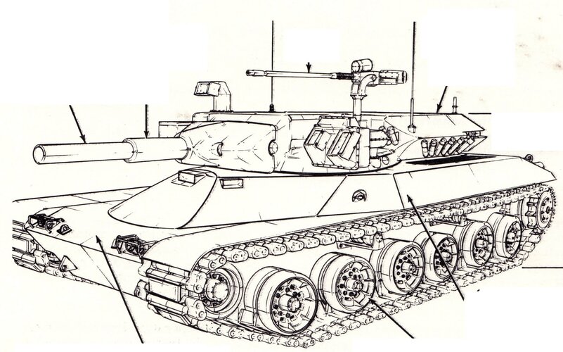
The frontal area had spaced armor, with two layers spaced with 127mm (5 inches), with the inner layer being a softer steel repalcing the classic spall liner over 46mm (1.18 in) and the outer layer made of harder cold-rolled steel 34mm (1.3 in). NBC was also planned from the start, with provision made for the installation of a polyethylene radiation shielding taunted to shield the crew at 20:1 against neutron radiation.
Here are the paragraphs describing the Soviet lining:
Furthermore, the T-72 had a thick internal anti-radiation lining on the surfaces of the turret and hull. On the frontal cheeks of the turret where the armour was thickest, the lining was only 10-20mm thick as the armour itself provided good shielding from penetrating radiation such as gamma rays and neutrons, but on other parts of the tank including the sides, rear, and ceiling of the turret, the sides of the hull, and on the autoloader carousel cover, the anti-radiation lining was 45-50mm thick to compensate for the low thickness of armour. This lining was known as "Podboi". Beginning in 1983, an external anti-neutron cladding with a thickness of 50mm was added on the turret and hull surrounding the inhabited parts of the tank as a response to an announcement by U.S president Ronald Reagan in 1981 that the production of neutron bombs would be restarted. This cladding was known as "Nadboi". Both the internal lining and external cladding were made from a laminate of hydrogen-rich polyethylene (UHMWPE) and polyisobutylene sheets impregnated with lead.
Besides offering excellent protection from harmful radiation and blast waves as detailed in Part 2 of this T-72 article, the thick anti-radiation lining inside and outside the tank provides thermal insulation for the crew and internal equipment in hot and cold weather. In cold weather, the temperature of the steel shell of a tank eventually equalizes with the outside temperature so that the crew would essentially be sitting in an ice box, and when the temperature drops below 0 degrees Celsius, the steel surfaces of a tank become too cold to be touched safely with bare skin. The same is true in hot weather as the interior of a tank heated by direct sunlight will become hotter than the ambient air temperature, given enough time. The laminated polymer material (polyethylene and polyisobutylene) of the anti-radiation lining acts as an insulator and a physical barrier between the steel shell of the tank and the crew, thus ensuring that the crew cannot accidentally burn or freeze themselves on the bare steel surface while also helping to regulate the internal temperature of the tank; in winter, the lining helps retain heat inside the crew compartment, and in summer, the lining helps prevent the heated steel shell from raising the internal temperature. The additional "Nadboi" cladding found on newer tanks adds another layer of insulation that is particularly useful in summer as the turret roof is the most exposed to sunlight.

 
Last edited:

Similar threads

Back
Top Bottom