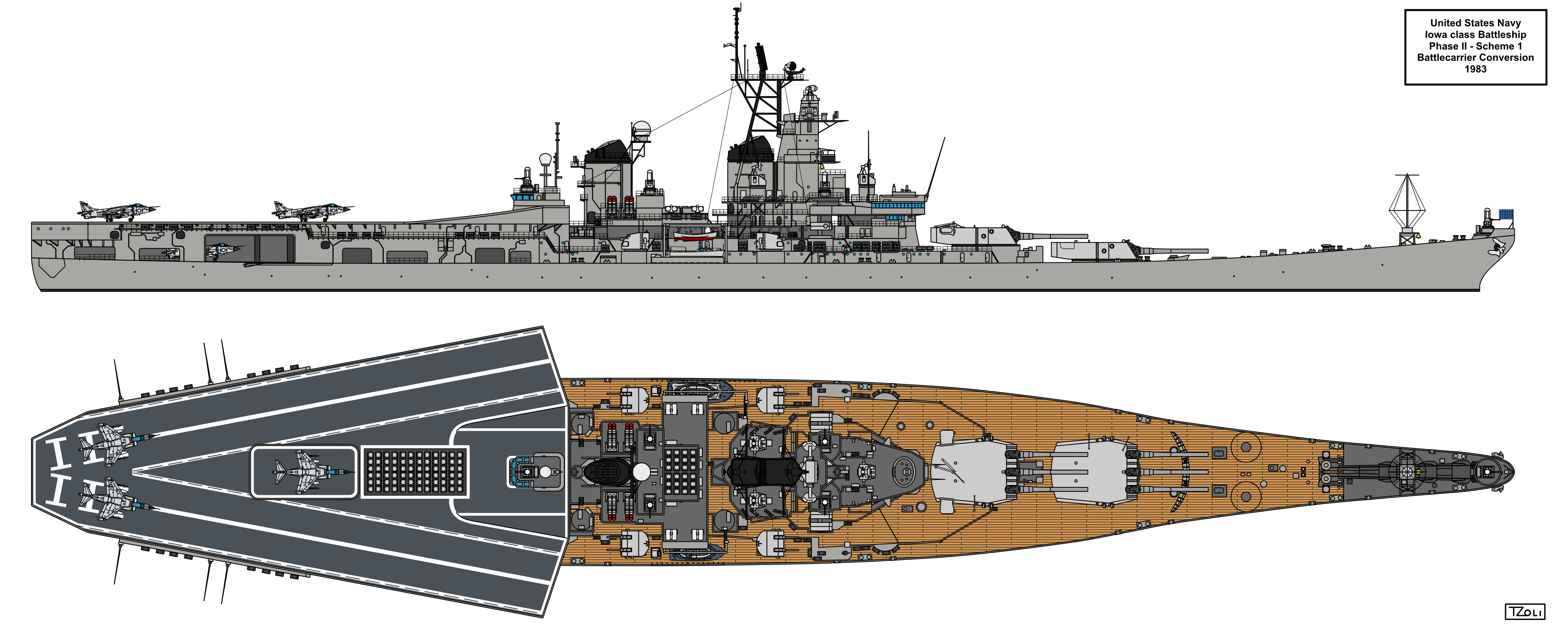
The Tomahawk VLS cells intended for the Phase II Scheme 1 - VSTOL (Battlecarrier / Aviation Battleship) conversion was stated 96 cells.
In my current drawing I've distributed these in 1x60 and 4x9 cells.
Now I'm thinking improving that drawing (As I recently finished all 4 Iowa Phase I drawings) and now I have these arrangement for the VLS:
1x60, 1x20, 4x4.
The 4x4 are at the old 5" barbettes or currently where my 3x3 cells are while the 20 cell pack I though between the Sea Sparrow "Bugeye" Directors in a 4-6-6-4 line (or 2-4x4-2 depending on view).
Alternatively I can lengthen the Flight Deck cell pack to 72 cells in a 6x12 arrangement which would reduce the equipment space of the hanger area somewhat. and reduce the 20 cell pack to just 8 cells.
I'm not sure who stated 96 cells. If you are aiming for fidelity to the historical Phase II aviation concept,* I don't think there should be VLS in the old 5-inch mounts at all. The drawing presented by the Navy to Congress in 1981 retains six 5"/38 turrets and shows only a block of 66 "cells" in a 6x11 grid aft of the superstructure, but the VLS doesn't look like it's drawn to scale. The Martin Marietta proposal displayed in 1982 retains two 5"/38 turrets and replaces the other four with FMC 155mm Vertical Loading Guns. It has a 16x20 VLS block (320 cells or forty 8-cell modules) in same basic location, but it seems out of scale in the other direction. I think both were done before the precise configuration of Mk 41 was publicly known and don't show things like breaks between modules or the exhaust plenums. That's consistent with other early sketches of VLS installations that did not account for such things.
What I would do is measure off those two drawings to find the rough size of the VLS block and see how many 8-cell modules can fit. (They're in
Hybrid Warships by Layman and McLoughlin if they aren't somewhere in this thread.) I would expect rather more than 8 (64 cells) but way less than 40 (320 cells). You might also want to consider whether or not you are trying to fit the VLS inside the armored caisson for the aft turret, which is probably smaller than you think. Cutting that out would be a chore but building in/around it could also be a challenge.
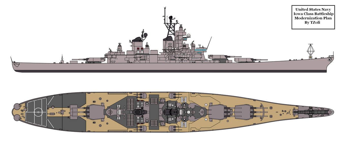
* Tangentially, Phase II studies were not just about the hybrid aviation ship. There were other designs with all three turrets and improved C2 facilities, two turrets forward and some mix of helicopter facilities and missiles aft, and even one with no turrets and ~400 VLS cells.


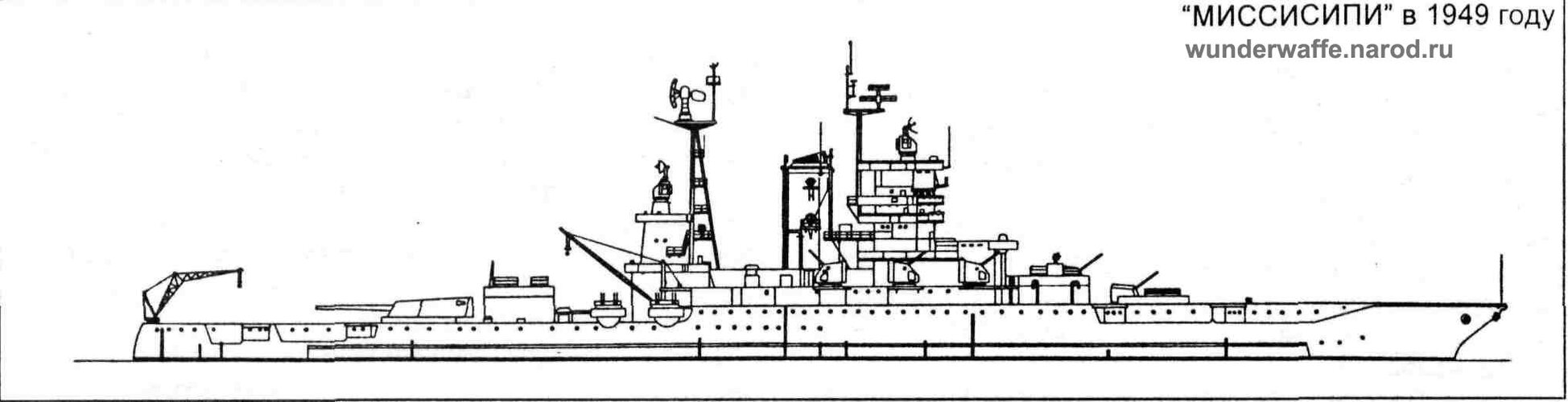
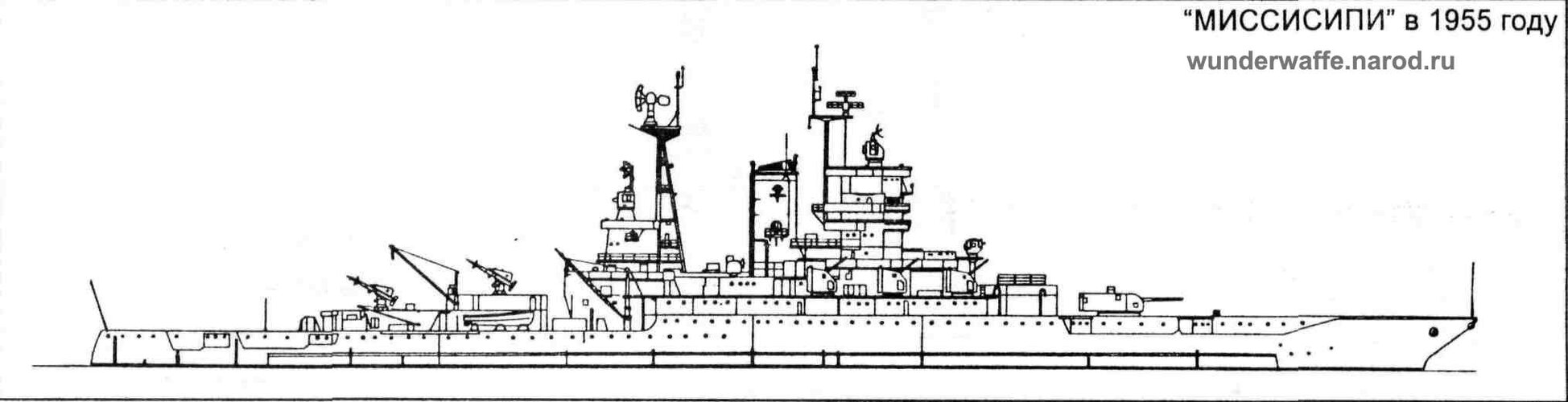
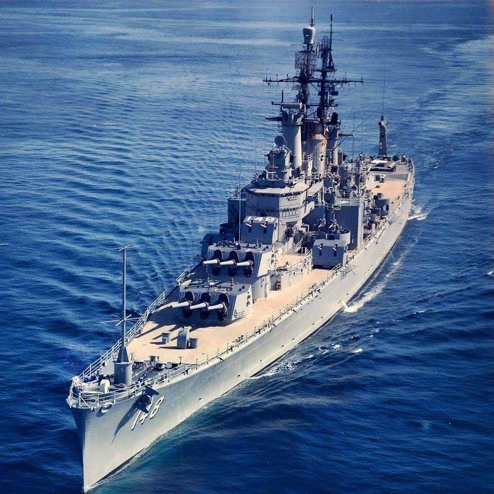
") ) as artillery/missile platforms. Rear turrets of "Idaho" removed, and adapted version of RIM-2 Terrier launchers (vertical drum magazine, like on "Boston"-class) are jury-rigged over hollowed barbettes.
) as artillery/missile platforms. Rear turrets of "Idaho" removed, and adapted version of RIM-2 Terrier launchers (vertical drum magazine, like on "Boston"-class) are jury-rigged over hollowed barbettes.