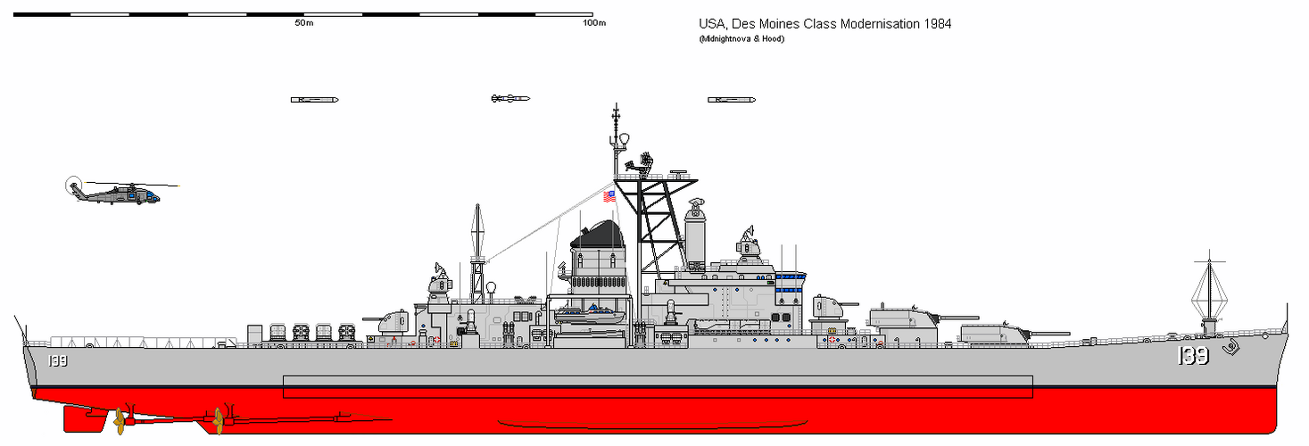
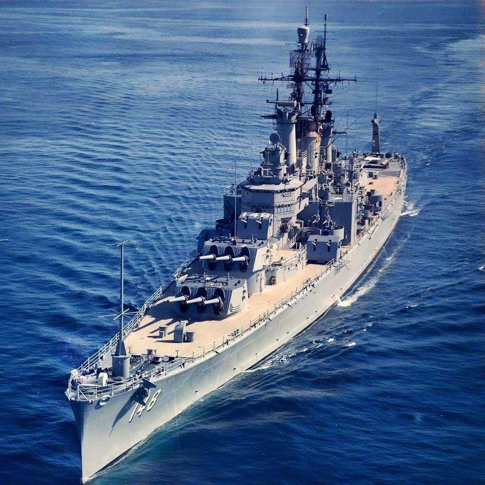
I wonder if Gene Anderson drew inspiration from the late 1967 Fire Support Ship (Monitor) proposals of he Naval Ship Engineering Center:
Seems not; just the parallel evolution of concepts. 1967s ship was quite obvious monitor, designed specifically for coastal support role and nothing else. Gene Anderson's light battleship was a bizzare "flag demonstration capital ship", fitted with systems that Gene seemingly poorly understood (like his idea to put Mk-26 SAM launchers on her in rather... strange positions, and with zero fire control radars).
 
Now that would be one bizarre alternate history "Colorado class in Korean and Vietnam war..."
Weeeeeeeel...
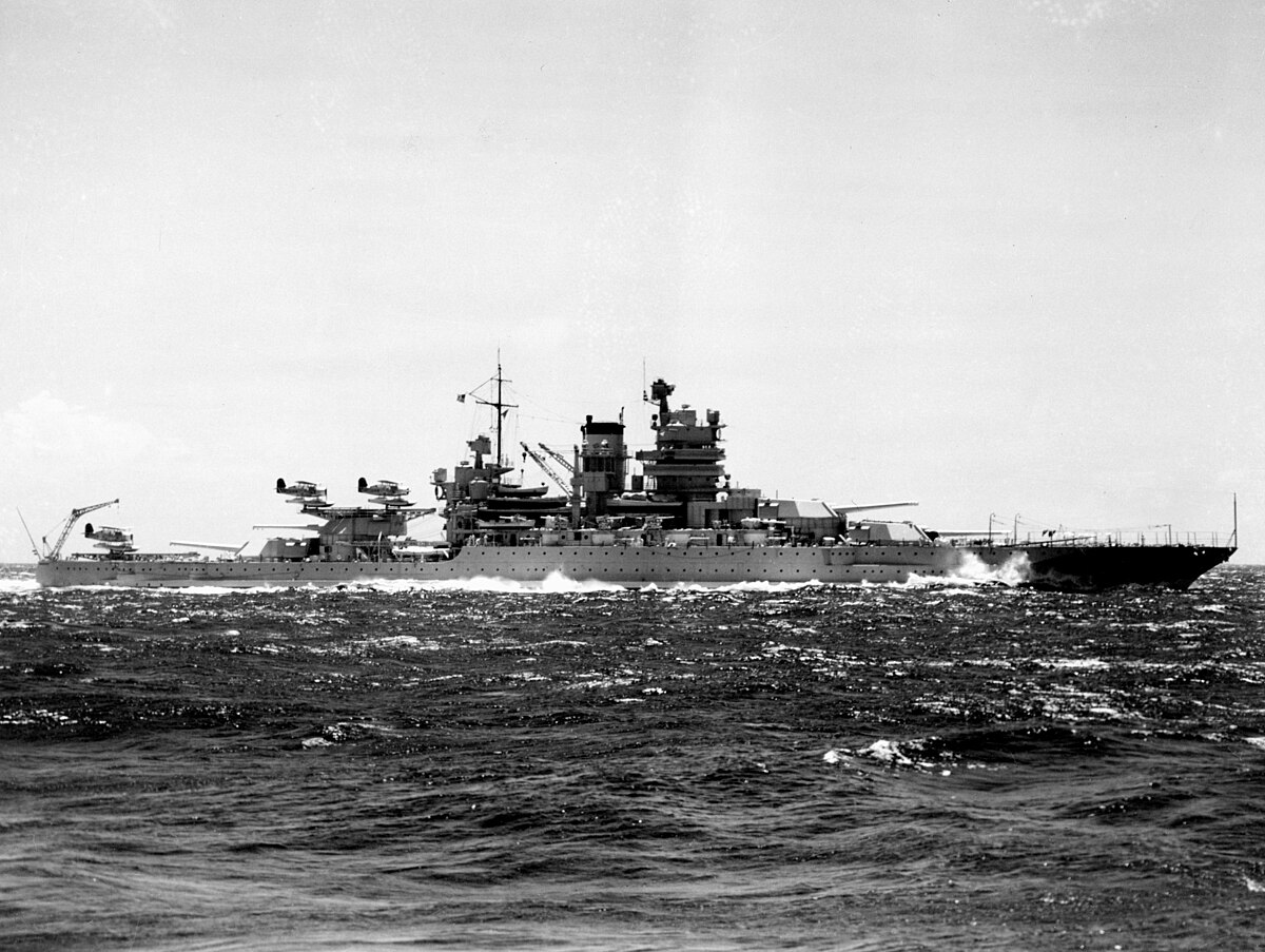
BBG Idaho 2.jpg

My old idea of "standard" battleship recommissioned in late 1950s (for the war against fascist India-based regime :) ) as artillery/missile platforms. Rear turrets of "Idaho" removed, and adapted version of RIM-2 Terrier launchers (vertical drum magazine, like on "Boston"-class) are jury-rigged over hollowed barbettes.
 
These BBG are real...
I dunno, I'd want more evidence than a Wunderaffe.narod image to be honest...
Well, USS Mississippi was used as a test ship for AAM systems, specifically the RIM-2. But by the time she was used for that, all of her main battery turrets and guns had been removed. Immediately after the war, her 1, 2, and 3 turrets were removed and replaced with 6", 5", 3", and 40mm weapons and she was used as a gunnery training ship. So she was never really a BBG. Hell, she didn't even retain her "BB" designation after 1945. She was reclassified as AG-128 (despite the fact that she served as the flagship for Battleships-Cruisers Atlantic Fleet for a month in 1947).
 
Isn't Des Moines's 8" RF gun turret was tested on her as well?
 
Isn't Des Moines's 8" RF gun turret was tested on her as well?
No. There were plans to replace her #3 turret with an 8" RF turret, but it was never actually installed.
It was the Mk 16DP twin turret to test for the Worcester class. The turret was installed in 1946 apparently.
The 6" guns and turret were installed. I believe where #1 Turret used to be. But there were also plans to install an 8" turret at fitted on the Des Moines class where #3 turret was. But it was never installed
 
The 6" guns and turret were installed. I believe where #1 Turret used to be. But there were also plans to install an 8" turret at fitted on the Des Moines class where #3 turret was. But it was never installed
"Can I have one of everything please" :p
Lol! Well, it was meant to be a gunnery training ship, so it was armed with pretty much every gun and mount in use by the Navy with the exception of 8" and 16" guns
 
Almost.
This one:
main-qimg-2a1627f322708c6b99b1e95f18a06346

2482d155adc3bcd9279592e55c5b4557.jpg
 
Yeah I've read that too, I imagine that's one issue that would have been corrected if they built a second batch of them or an improved follow-on class.
 
I appreciate that this is partly 'wandering off' from the primary title of this particular discussion, but here goes anyway...
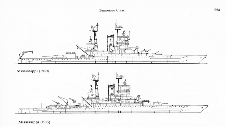
Illustrations of USS Mississippi showing post WW2 modifications as trials ship - Taken from the late Siegfried Breyers "Battleships and Battle Cruisers 1905-1970" (English language edition), which seems to be where the Wunderaffe.narod image originates from.

Also, an article from "Naval Engineers Journal", May 1984 "Designe for New Jersey, Iowa and Des Moines Modernization" (I have purposely used the American spelling of the last word, as that is the title of the article.
 

Attachments

  • Battleships and Battle Cruisers 1905-1970 - Siegfried Breyer .png
    Battleships and Battle Cruisers 1905-1970 - Siegfried Breyer .png
    1.4 MB · Views: 231
  • Des Moines and Iowa Modernisation Plans BB-61_NEJ-96-3-25-1984 Desmoines.pdf
    1.6 MB · Views: 88
Thanks for locating the source of those images.
Given how so many manipulated ship linedrawings are floating around the internet from the early 2000s its wise to double-check.
 
The Tomahawk VLS cells intended for the Phase II Scheme 1 - VSTOL (Battlecarrier / Aviation Battleship) conversion was stated 96 cells.
In my current drawing I've distributed these in 1x60 and 4x9 cells.
Now I'm thinking improving that drawing (As I recently finished all 4 Iowa Phase I drawings) and now I have these arrangement for the VLS:
1x60, 1x20, 4x4.
The 4x4 are at the old 5" barbettes or currently where my 3x3 cells are while the 20 cell pack I though between the Sea Sparrow "Bugeye" Directors in a 4-6-6-4 line (or 2-4x4-2 depending on view).
Alternatively I can lengthen the Flight Deck cell pack to 72 cells in a 6x12 arrangement which would reduce the equipment space of the hanger area somewhat. and reduce the 20 cell pack to just 8 cells.

I'm not sure but maybe the USN preferred 2x2 or 4 cell blocks?
The Mark 41 launcher comes in 8-cell (2x4) blocks; that's a fundamental part of the system architecture and can't be changed without significant expenditure. As far as I know, it's always been installed with the long axis of each block perpendicular to the centreline; there may well be a reason for that. Obviously that restricts your layout options.
 
I'm not sure it would be difficult or too expensive to make a half 2x2 cell block.
 
I'm not sure it would be difficult or too expensive to make a half 2x2 cell block.

Historically, one limiting factor was the control electronics; each 8-cell block had the necessary electronics to warm and fire two missiles in rapid succession. But that was just a technical and economic choice, and there's no reason other module sizes couldn't have been done even in 1982. The one big constraint would be that you have to ensure that each cell in the module is adjacent to an exhaust plenum of sufficient size, especially for a restrained firing, which does make a 3x3 block less plausible (though maybe an 8-cell block arranged 3x3 with a central plenum could be made to work). A 2x2 half-module with single firing electronics would be quite reasonable.

Today, LM is offering a Single-Cell Launcher based on the Mk41 architecture, with each tube having it's own exhaust plenum, and SCL does show a 2x2 arrangement as an option.

The Tomahawk VLS cells intended for the Phase II Scheme 1 - VSTOL (Battlecarrier / Aviation Battleship) conversion was stated 96 cells.
In my current drawing I've distributed these in 1x60 and 4x9 cells.
Now I'm thinking improving that drawing (As I recently finished all 4 Iowa Phase I drawings) and now I have these arrangement for the VLS:
1x60, 1x20, 4x4.
The 4x4 are at the old 5" barbettes or currently where my 3x3 cells are while the 20 cell pack I though between the Sea Sparrow "Bugeye" Directors in a 4-6-6-4 line (or 2-4x4-2 depending on view).
Alternatively I can lengthen the Flight Deck cell pack to 72 cells in a 6x12 arrangement which would reduce the equipment space of the hanger area somewhat. and reduce the 20 cell pack to just 8 cells.

I'm not sure who stated 96 cells. If you are aiming for fidelity to the historical Phase II aviation concept,* I don't think there should be VLS in the old 5-inch mounts at all. The drawing presented by the Navy to Congress in 1981 retains six 5"/38 turrets and shows only a block of 66 "cells" in a 6x11 grid aft of the superstructure, but the VLS doesn't look like it's drawn to scale. The Martin Marietta proposal displayed in 1982 retains two 5"/38 turrets and replaces the other four with FMC 155mm Vertical Loading Guns. It has a 16x20 VLS block (320 cells or forty 8-cell modules) in same basic location, but it seems out of scale in the other direction. I think both were done before the precise configuration of Mk 41 was publicly known and don't show things like breaks between modules or the exhaust plenums. That's consistent with other early sketches of VLS installations that did not account for such things.

What I would do is measure off those two drawings to find the rough size of the VLS block and see how many 8-cell modules can fit. (They're in Hybrid Warships by Layman and McLoughlin if they aren't somewhere in this thread.) I would expect rather more than 8 (64 cells) but way less than 40 (320 cells). You might also want to consider whether or not you are trying to fit the VLS inside the armored caisson for the aft turret, which is probably smaller than you think. Cutting that out would be a chore but building in/around it could also be a challenge.

* Tangentially, Phase II studies were not just about the hybrid aviation ship. There were other designs with all three turrets and improved C2 facilities, two turrets forward and some mix of helicopter facilities and missiles aft, and even one with no turrets and ~400 VLS cells.

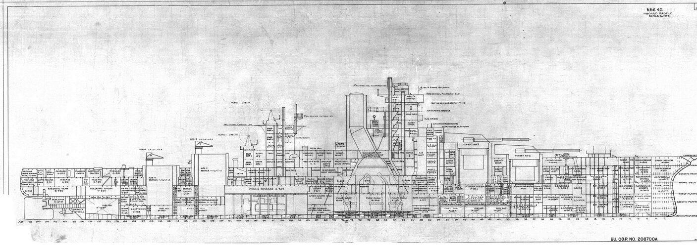
Here are my source for the Scheme 1 VSTOL:
2x3 16" 4x2 5" 2x8 Sea Sparrow, 4x4 Harpoon, 96x VLS Tomahawk

And
 

Ah, OK. Solid source then. But I would say that the VLS is likely all in one big block of 96 cells (12 modules) aft of the superstructure (either 3x4 or 2x6). There's no reason to shoehorn small blocks of cells into the old 5-inch barbettes.
 
My idea that they are not in one place hence would not be destroyed by a single hit and the 5" barbettes provide some protection.
It would be nice to read the original (USN) texts for these proposals to know how they thought of VLS arrangement.
 
Yeah, but the one official sketch we have of Phase II shows the VLS in one block, so I think that's the most likely solution by far.
 
Yeah, but the one official sketch we have of Phase II shows the VLS in one block, so I think that's the most likely solution by far.
I thought that was the elevator.
 
Yeah, but the one official sketch we have of Phase II shows the VLS in one block, so I think that's the most likely solution by far.
I thought that was the elevator.

No, it's the VLS. The elevator was right behind the VLS (alternatively, the Hybrid Warships sketch of the Martin Marietta design shows two elevators out near the deck edge, plus the vertically loading guns not seen on the model).

Also in this thread: https://www.secretprojects.co.uk/threads/iowa-and-alaska-class-conversion-projects.7220/post-360182

This has pictures from two iterations of a model, which was clearly not very representative forward of the flight deck structure. One shows an elevator aft of the VLS, another matches the Hybrid Warships sketch with two deck edge pocket elevators. The drawing does not show an elevator at all. It appears to be an annotated version of McLaughlin's drawing in Hybrid Warships.
 
What is the issue with the elevator right behind the VLS pack? It's structure helps with the support of the elevator I think
 
What is the issue with the elevator right behind the VLS pack? It's structure helps with the support of the elevator I think

I don't know that there was an issue, except that one elevator can become a single point of failure when it breaks. OTOH, the two side elevators each can block a takeoff lane while lowered and would seem to eat up more space in the hangar. So, could go either way.

It's not like these were final designs. They barely got past the napkin sketch stage here.
 
Last edited:
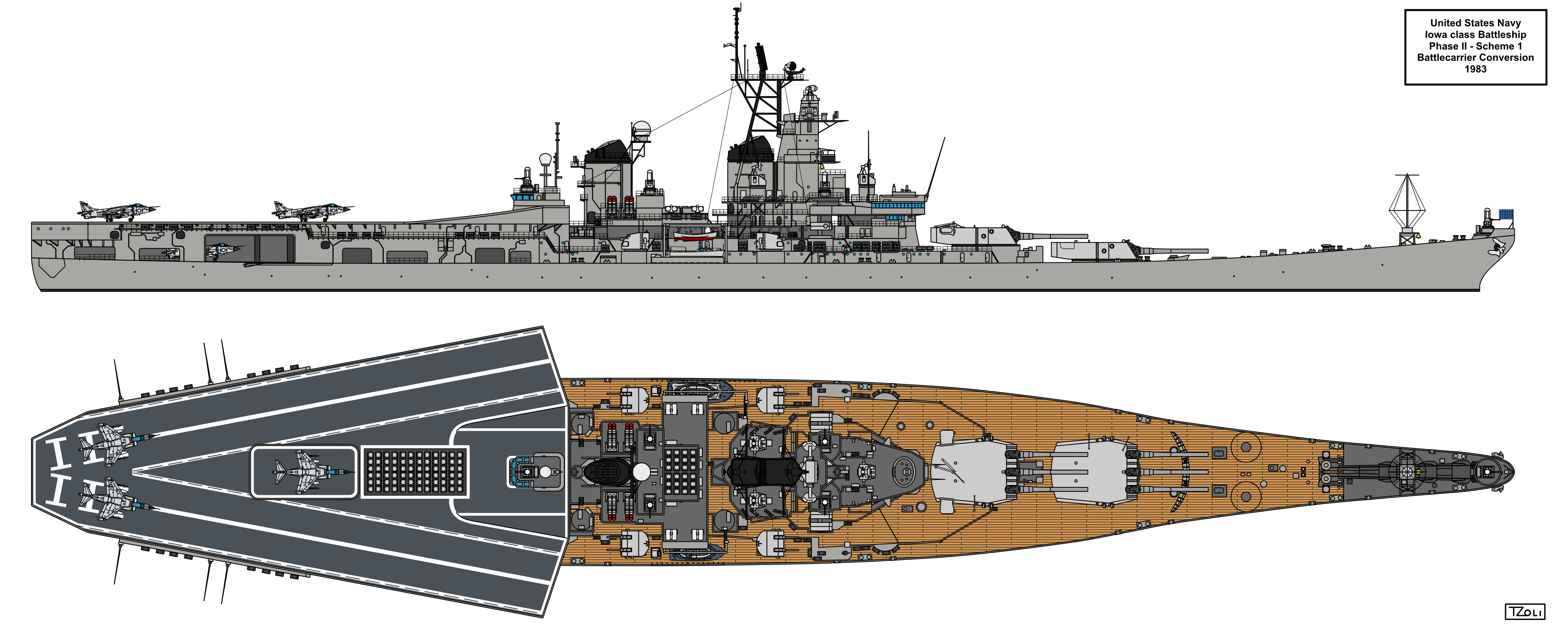
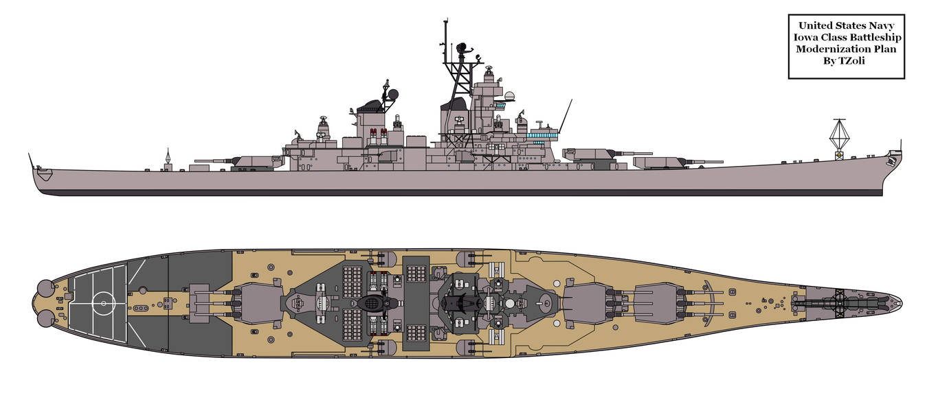
Here is my updated drawing of the Phase II Scheme 1 Battlecarrier or Aviation Battleship proposal:
dda14sc-227e25cd-097b-4808-9430-95932a53b16c.png


I've used the New Jersey as a basis, modified the VLS layout to 2 groups: 1x72 and 1x24 blocks and I've replaced the 2D SPS-49 with the 3D SPS-48 Air Search Radar but I still need to search for drawings of the SPN-43 and SPN-44 radars required for the air control operations
 
In the old now dead Warship Projects 3.0 forum, a member told be that there were to be a modest Phase II upgrade with these changes:
- The removal of one set of 5inch 38 calibre twin DP-AA Gun turrets and place RIM-7 Sea Sparrow Box Launchers in their place, together with associated Mark 95 "Bug Eye" Illumination radars
- Replace the gun barrels of the existing (4) 5inch DP-AA Gun turrets to the longer 54 calibre ones. The change would result in a slightly enlarged turret to hold the larger recoil of the guns.
- Replace the Armoured Box Launchers of the BGM-109 Tomahawk missiles with 2x16 and 2x32 Vertical Launch Cells, totalling the missile number to 96.
- Add a removable hanger aft of the 3rd main Gun Turret for the RQ-2A Pioneer Umanned Aerial Vehicles
- Target Acquisition Radar System on the aft funnel for the Sea Sparrow Missiles
- Various superstructure changes according for the install of the equipments mentioned above

Do you guys heard of it? Based on the armament and enlarged Pioneer hanger I think it was proposed in the late 1980's early 1990's after the first batch of Phase II proposals.

Many years ago I've made a drawing based on the description:
 
Last edited:
- Replace the gun barrels of the existing (4) 5inch DP-AA Gun turrets to the longer 54 calibre ones. The change would result in a slightly enlarged turret to hold the larger recoil of the guns.

I'm pretty sure this is not possible. You could possibly come up with a way to fit a longer barrel but there would be no point because you'd still have to fire the old 5"/38 ammo out of it. The new 5"/54 ammo is substantially larger and would not fit the old gun at all.
5"/54 projectiles are nearly 6 inches longer and 14 pounds heavier than those for 5"/38. The propellant cases are likewise both longer and heavier. No parts of the gun, hoist, loading tray, or rammer are going to be ok with that unless you do a lot of retrofitting.

Consider, the actual Mk 16 5"/54 semi-automatic gun was essentially a scaled-up version of the 5"/38, and the single Mk 39 turret for that weighed around 33 tons. The comparable 5"/38 Mk 30 weighed a bit less than 19 tons. No amount of retrofitting of the Mk 30 was going to make it work with the new ammo. There's a reason this was never proposed for the literally thousands of old 5"/38 mounts in the world.

If 5"/54 was desired, the only viable path (which was proposed) was to retrofit Mk 45 mounts. They weigh just over 22 tons (excluding hoists) and could actually be made to fit as a nearly direct replacement. But then again, why bother given that there were hundreds of thousands of 5"/38 rounds left in inventory?
 
Don't ask me I just quoted that old post. Sadly I could not even ask the person who provided the info with from where it was sourced.
He did said this that because of the longer barrels the turret aft part had to be modified. (And I've do seen shipbucket drawings with such modified 5" twin turrets on the Iowas)
But indeed it would be most cost effective to not replace them or if they wanted considerable upgrade in gunnery AA, use the 5"/56 Mark 19 guns in single mountings or even the then under development 5"/62 mark 36 gun.
 
(And I've do seen shipbucket drawings with such modified 5" twin turrets on the Iowas)
http://www.shipbucket.com/drawings/7563/file http://www.shipbucket.com/drawings/7562/file
I drew those so long ago that I can't remember where those gun mounts came from. Could well have been a crappy shipbucket part (things were a lot more inaccurate in those days), probably does date from around the time of Warship 3.0s demise, though I can't recall the discussion so don't think that fed into my work, these were based on the drawings from Hybrid Warship.
 
I actually believe I read somewhere (maybe here) that the Navy had dug the plans for the Mark 41 twin gun mount for the 5"/54 caliber Mark 16 out of the archives and was planning on building those for the Phase 2 upgrade of the Iowas. Those used bagged charges but I believe they should have been able to use the same projectiles as the Mark 45. For some reason it was determined that putting in Mark 45s there would not be feasible.
 
I actually believe I read somewhere (maybe here) that the Navy had dug the plans for the Mark 41 twin gun mount for the 5"/54 caliber Mark 16 out of the archives and was planning on building those for the Phase 2 upgrade of the Iowas. Those used bagged charges but I believe they should have been able to use the same projectiles as the Mark 45. For some reason it was determined that putting in Mark 45s there would not be feasible.

I've never heard that. It seems improbable, to say the least. Digging up the plans and recreating a mount that was never actually built but only drawn in the 1940s, using 1980s technology, would be a huge undertaking. It would have to be easier to fix whatever was wrong about the Mark 45 (probably the hoist arrangement).
 
Back
Top Bottom