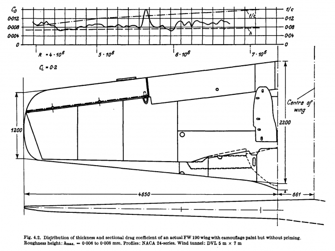
This drag distribution of the 190s wing from DVL testing shows a non-linear thickness distribution;

Was this continued on the Ta-152 wings?
Question for structural engineers:
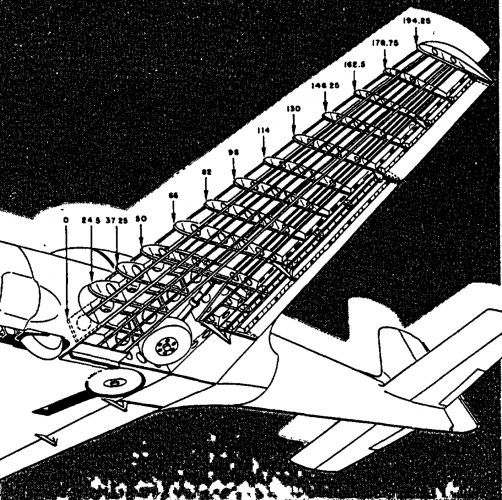
Could the of lateral stringer structure (153) fully compensate for the omission of the full- length main spar?


View attachment 795928
Yes
 

Attachments

  • navion wing.png
    navion wing.png
    1.3 MB · Views: 166
  • 190 wing real drag.png
    190 wing real drag.png
    308.7 KB · Views: 180
Last edited by a moderator:
Hi,

Is this a proposal or the description of what was actually built? (It sounds like a proposal)

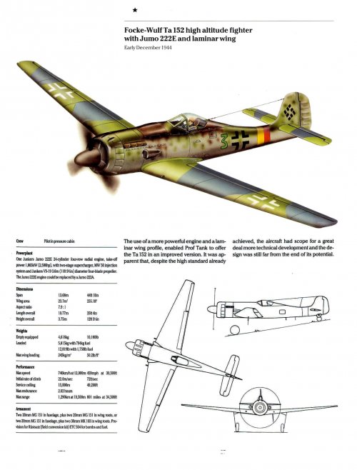
That's just a proposal, it simply assumes that a special version of the Jumo 222 would be built for the proposed Ta 152 variant.

The motivation for building a new wing is given in the proposal as follows:

"Since retaining the wing of the Ta 152 H would result in an excessively low G limit at the flying weight of the variant Ta 152 with Jumo 222, it's necessary to develop a new wing. For the new wing the latest aerodynamic knowledge will be taken into account by transitioning the airfoil from the original root airfoil, which will be retained near the fuselage, to a laminar airfoil at the landing gear attachment point."

Regards,

Henning (HoHun)
 
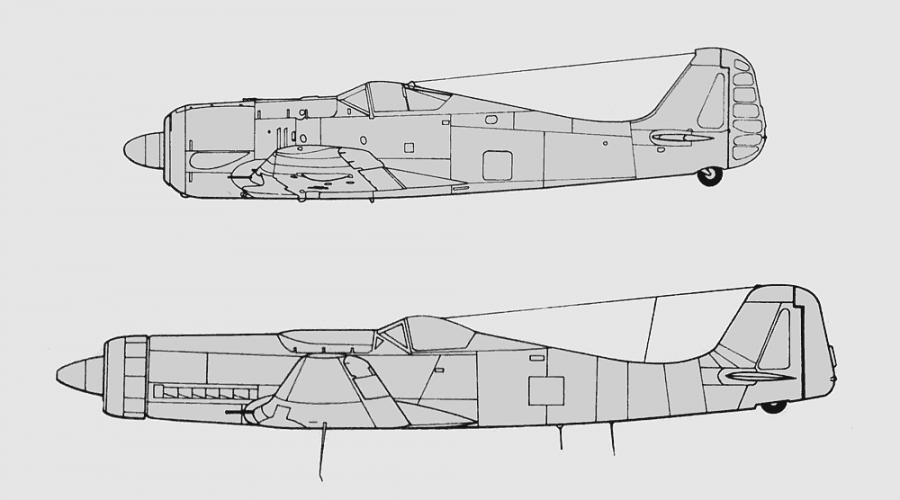
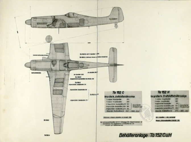
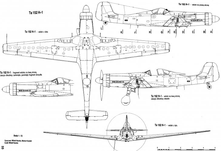
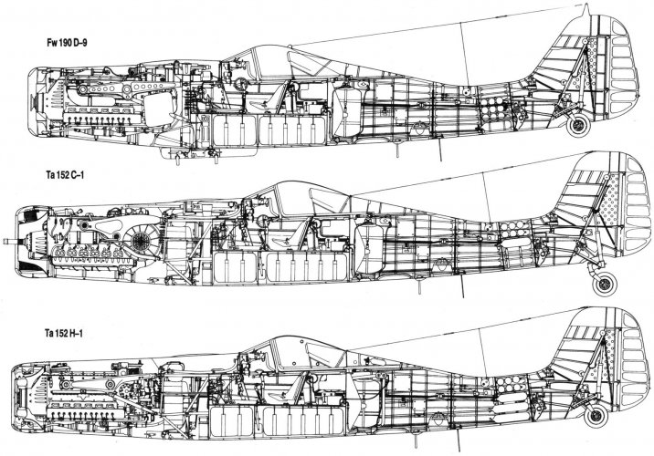
Some more reference material.

Regards,
 

Attachments

  • 1CFBHtK.jpeg
    1CFBHtK.jpeg
    427 KB · Views: 738
  • 71925a30dc37a1642e3b456a5d831d43.jpg
    71925a30dc37a1642e3b456a5d831d43.jpg
    120.1 KB · Views: 764
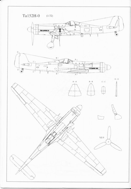
  • Artwork-Focke-Wulf-Ta-152H0-blue-print-line-drawing-1.72-scale-01.jpg
    Artwork-Focke-Wulf-Ta-152H0-blue-print-line-drawing-1.72-scale-01.jpg
    130.5 KB · Views: 799
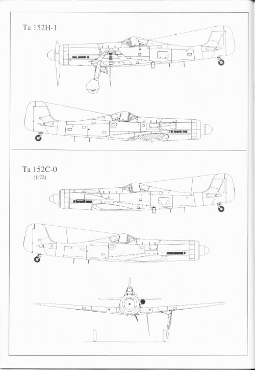
  • Artwork-Focke-Wulf-Ta-152H1-blue-print-line-drawing-1.72-scale-01.jpg
    Artwork-Focke-Wulf-Ta-152H1-blue-print-line-drawing-1.72-scale-01.jpg
    120.2 KB · Views: 832
  • D9.jpg.788e74b6468de4ffa978446febbf7d9f.jpg
    D9.jpg.788e74b6468de4ffa978446febbf7d9f.jpg
    1.2 MB · Views: 899
Last edited by a moderator:
And more,

Regards,
 

Attachments

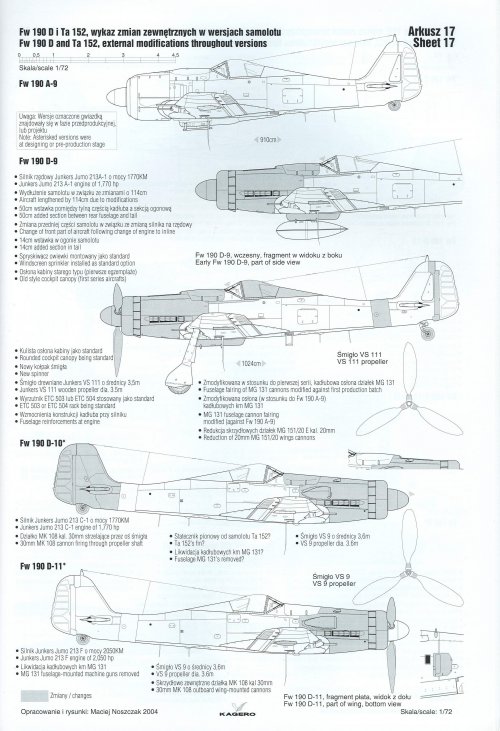
  • Modelart-Fw-190D-Ta-152-2.jpg
    Modelart-Fw-190D-Ta-152-2.jpg
    96.3 KB · Views: 922
  • Modelart-Fw-190D-Ta-152.jpg
    Modelart-Fw-190D-Ta-152.jpg
    60.2 KB · Views: 912
  • fw19401.png
    fw19401.png
    76.4 KB · Views: 901
  • fw190sided9.png
    fw190sided9.png
    351.8 KB · Views: 911
  • f7902f298362792.jpg
    f7902f298362792.jpg
    550.7 KB · Views: 905
  • red.png
    red.png
    2.3 MB · Views: 921
Last edited by a moderator:
Some more,

Regards,
 

Attachments

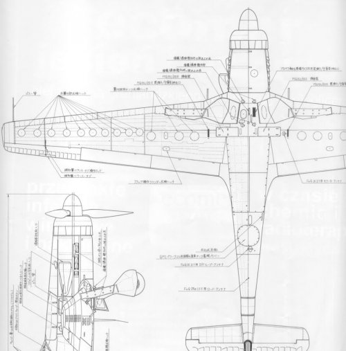
  • Z-15.JPG
    Z-15.JPG
    130.2 KB · Views: 950
  • Z-14.JPG
    Z-14.JPG
    150 KB · Views: 923
  • WGUMsTx.jpeg
    WGUMsTx.jpeg
    644.1 KB · Views: 925
  • fw-190a-3-and-ta-152h-1-fighter-aircraft.png
    fw-190a-3-and-ta-152h-1-fighter-aircraft.png
    31.5 KB · Views: 901
  • deutchesluftwaffede.png
    deutchesluftwaffede.png
    2.3 MB · Views: 917
  • Artwork-Focke-Wulf-Ta-152H0-blue-print-line-drawing-1.72-scale-03.jpg
    Artwork-Focke-Wulf-Ta-152H0-blue-print-line-drawing-1.72-scale-03.jpg
    799.7 KB · Views: 910
  • Ta_152C-1_H-1.jpg
    Ta_152C-1_H-1.jpg
    360.3 KB · Views: 899
Last edited by a moderator:
Tisztelt Justo Miranda Úr! Repüléstörténeti műszaki kutatásomhoz szeretném a segítségét kérni. Konkrétan a Focke-Wulf Ta 152 H-1 vadászrepülőgép szárnyközép és törzsközép csatlakozásának a részletei érdekelnének műszaki rajz, vagy vázlat és fotó segítségével. Tudna-e segíteni? Várom megtisztelő válaszát. Boldog Új Évet és minden jót kívánok!
Tisztelettel és nagyrabecsüléssel:
Kiss József,
Magyarország.
 
1767484860914.png
some data on the performance of the Juumo-213EB, is that an imporvment in exhaust thrust?
 
Not exactly a fan of the video tbh, Ta and Tar pronounced as a short thanks and Tarl etc. What the actual?
Information yes but, confused it is.
 
Hi! Turbo charged BMW 802 engine.
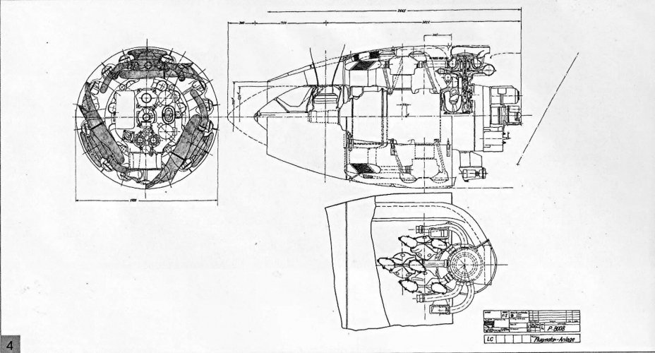
https://www.my3dbase.com/2023/06/focke-wulf-with-bmw-802-and-sub-variantshtml

"This seems to support the assumption that the BWM P.8011 was a sub-version of the 802 (or 801?). Information about that engine was at some point forwarded to BMW which integrated it into their design. As an example, P.8008 is depicted below. Wikipedia suggests two turbochargers for the P.8011. I do not have access to any source supporting that statement. P.8011 might as well featured 3 turbo chargers as P.8008."
 

Attachments

  • bmw+802+verion+3-4cd5a384-1920w.jpg
    bmw+802+verion+3-4cd5a384-1920w.jpg
    210.6 KB · Views: 130
Last edited:
Hi!
 

Attachments

  • Ta 152 with jumo222E and laminar wing.jpg
    Ta 152 with jumo222E and laminar wing.jpg
    234.5 KB · Views: 95
A decade, give or take, before anyone else, Sanford Moss was perfecting the turbocharger. His invention and perfecting it meant the US had a device that could make a piston engine work at altitudes nothing else could.
What would be these altitudes, and when (as in what year)?
 
What would be these altitudes, and when (as in what year)?
Do you get the difference in how a geared supercharger and a turbocharger work?

For the former, the engine speed determines the impeller speed and that is a fixed ratio. Thus, superchargers work with decreasing efficiency as they move from their best altitude and engine speed. This is why two, and even three, stage superchargers were being put on aircraft during WW 2. The Allison V 1710 had a single speed supercharger and that ran out of steam, so to speak, at about 15,000 feet.

When you go to a turbocharger, the exhaust gas pressure driving the turbine can be varied with manifold pressure and altitude to give a constant input pressure to the engine. It's as easy as having a waste gate to dump excess exhaust pressure to maintain a constant turbo boost on for the engine. They are far less dependent on altitude as a variable for performance.

Turbochargers are typically more fuel efficient. Turbochargers are driven by the engine’s exhaust gases, which is considered a type of waste energy. Rather than allowing this energy to go to waste, it’s used to turn the turbocharger and boost the engine’s power and performance.

Turbochargers can also handle higher altitudes. Superchargers have a somewhat limited ceiling. At high altitudes, they become very inefficient. Turbochargers, though, can handle high altitudes while maintaining their efficient properties.
https://monroeaerospace.com/blog/aircraft-superchargers-vs-turbochargers-whats-the-difference/

https://www.flyhpa.com/2021/04/turbocharging-vs-supercharging/

https://www.flight-study.com/2021/02/superchargers-and-turbosuperchargers.html

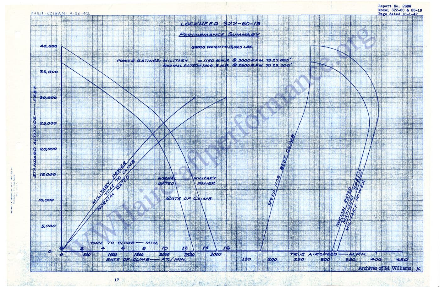
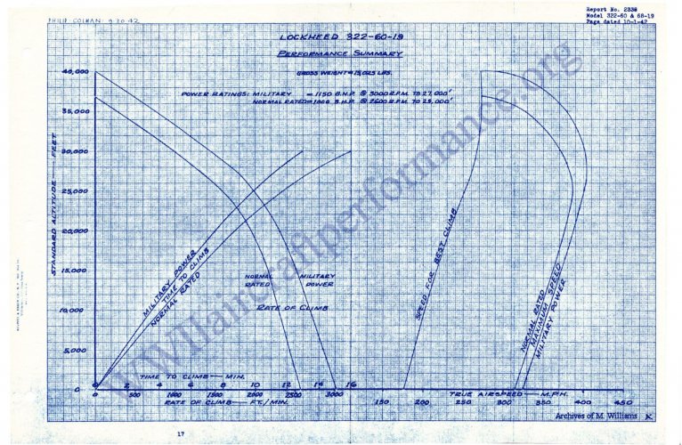
Here are the speed curves for a P-38 (turbocharged)

fbb8c61625fe9c7981065edc35b9d6c32e5dc511.jpeg


Notice how they are a smooth curve to a critical altitude where performance begins to fall off because the turbocharger can only supply so much compression as the air thins (wastegate fully shut).

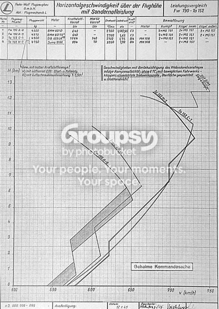
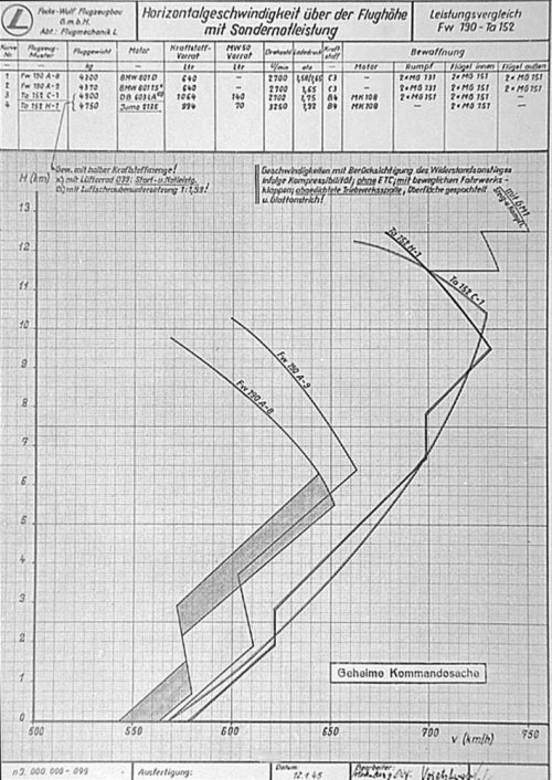
Here are the ones for an FW 190 and Ta 152

Fw190A8_A9Ta152speed.jpg


Note the jagged lines. These mark the points where the supercharger changes gears. As you get away from those points, performance drops off markedly.

This is why a turbocharger, even for its drawbacks like turbo lag, is superior to a geared supercharger.

 

Attachments

  • Fw190A8_A9Ta152speed.jpg
    Fw190A8_A9Ta152speed.jpg
    161.8 KB · Views: 39
  • fbb8c61625fe9c7981065edc35b9d6c32e5dc511 (1).jpeg
    fbb8c61625fe9c7981065edc35b9d6c32e5dc511 (1).jpeg
    329.4 KB · Views: 55
Last edited:
Turbochargers can also handle higher altitudes. Superchargers have a somewhat limited ceiling. At high altitudes, they become very inefficient. Turbochargers, though, can handle high altitudes while maintaining their efficient properties.
This is incorrect. Superchargers and turbochargers of the time used centrifugal compressors, they were about the same efficiencies.

Superchargers have issues with altitude for the same reason turbos do, they need way higher pressure ratios than what a single stage can efficiently put out. Hence mutli-stage and mutli-speed superchargers, and in the case of turbos they were almost always turbo-supercharged, ie the turbo in the P-47 fed a regular centrifugal supercharger, which means they were multi-stage as well.
This is why a turbocharger, even for its drawbacks like turbo lag, is superior to a geared supercharger.
For one turbo lag means nothing in an aircraft powerplant.

But more importantly the trade-offs between super vs turbo is much more complex than you lay out, especially in the case of fighters. General rule of thumb seems to be <30k feet superchargers offer superior thrust horsepower, which looks to be born out by real world experience.
 
Interestingly, in the new(ish) Focke Wulf Ta 152 book by T.H. Hitchcock (see cover below), the attached pic is also purported to be the Ta153.

41rYacb-ntL._SL500_AA300_.jpg


Regards,

Greg
I know this is a ghost reply but the image you attached is actually Fw 190 V21 (the last of the 3 190 airframes used for Ta 152A prototypes)
 

Attachments

  • Fw 190 V21.jpg
    Fw 190 V21.jpg
    87.4 KB · Views: 58
  • Fw 190 V21 1.png
    Fw 190 V21 1.png
    266.7 KB · Views: 50
  • Fw 190 V21 2.png
    Fw 190 V21 2.png
    261.7 KB · Views: 86
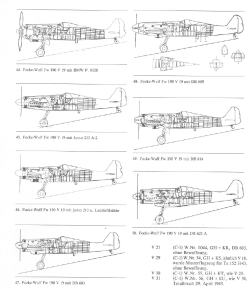
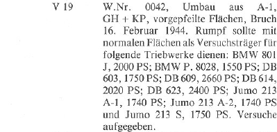
Saved from an old split topic, this Focke-Wulf Fw 190 V19 project:
this one is also a Fake project born in the 1970s, actual V19 was the first Ta 152 prototype. The confusion seems to stem possibly from the fact it first tests a new twin spar wing which they tested and went back to an old 190 A-3 wing.
 
The FW.190 V.19, Die Deutsche Luftruestung 1933-1945 - Vol.2 - Erla-Heinkel (Bernard&Graefe)
 

Attachments

  • 3.png
    3.png
    387 KB · Views: 94
  • 4.png
    4.png
    49.2 KB · Views: 138
I do believe all the test engine configs for V19 were cancelled because it crashed, it was however one of the main test airframes for the Jumo 213. Ive made a 3d model of the V19 with the DB 609 because its my favourite aesthetically
 
this one is also a Fake project born in the 1970s, actual V19 was the first Ta 152 prototype. The confusion seems to stem possibly from the fact it first tests a new twin spar wing which they tested and went back to an old 190 A-3 wing.
FW did study M-wings for the 190.
 
Last edited:
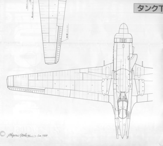
Wondering if anyone has some good schematics for the Fw 190B with the enlarged wing, had a look through here but couldnt find any, i bet some of you have some goodies stored up. Currently making a Fw 190 A-4 mod into a carrier airframe (alt history obvs) and was going to add 190B wings and make them fold at the ailerons. Cheers in advance
 
Last edited:

Similar threads

Back
Top Bottom