
You are using an out of date browser. It may not display this or other websites correctly.
You should upgrade or use an alternative browser.
You should upgrade or use an alternative browser.
CVA-01 1963 to 1966
- Thread starter GTX
- Start date
-
- Tags
- aircraft carrier amphibious warfare vessel anti-air warfare anti-submarine warfare area air defence cold war commando carrier cruiser fleet air arm great britain guided missile aviation cruiser helicopter carrier late 1960s north atlantic treaty organisation royal marines royal marines commandos royal navy v/stol aircraft vstol carriers vtol
- Joined
- 6 June 2006
- Messages
- 14,669
- Reaction score
- 20,614
France just had put Clemenceau and Foch in service, 1960 and 1963 respectively. Plus, the bulk of the military budget was swallowed by the Force de Frappe, notably the incoming missiles and submarines.
- Joined
- 31 July 2013
- Messages
- 619
- Reaction score
- 1,300
Thanks, I thoght that was the situation but just needed confirmationNo, there was no French involvement in CVA-01. There was Anglo-French AEW collaboration but that's as far as it went.
- Joined
- 31 July 2013
- Messages
- 619
- Reaction score
- 1,300
I have to admit i completely forgot how new the two French carriers were compared to the Uk examples in the 1960sFrance just had put Clemenceau and Foch in service, 1960 and 1963 respectively. Plus, the bulk of the military budget was swallowed by the Force de Frappe, notably the incoming missiles and submarines.
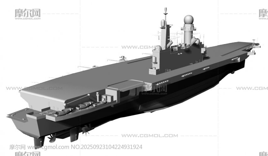
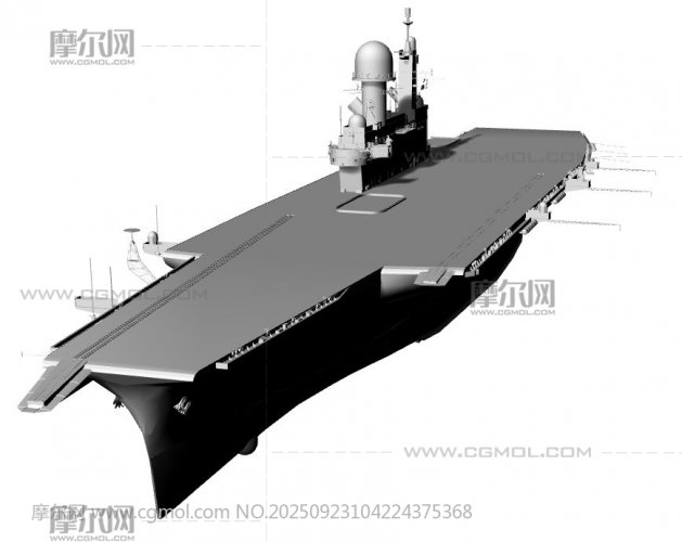
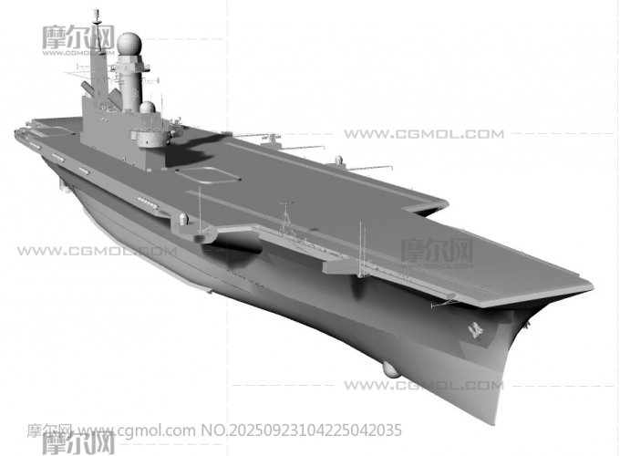
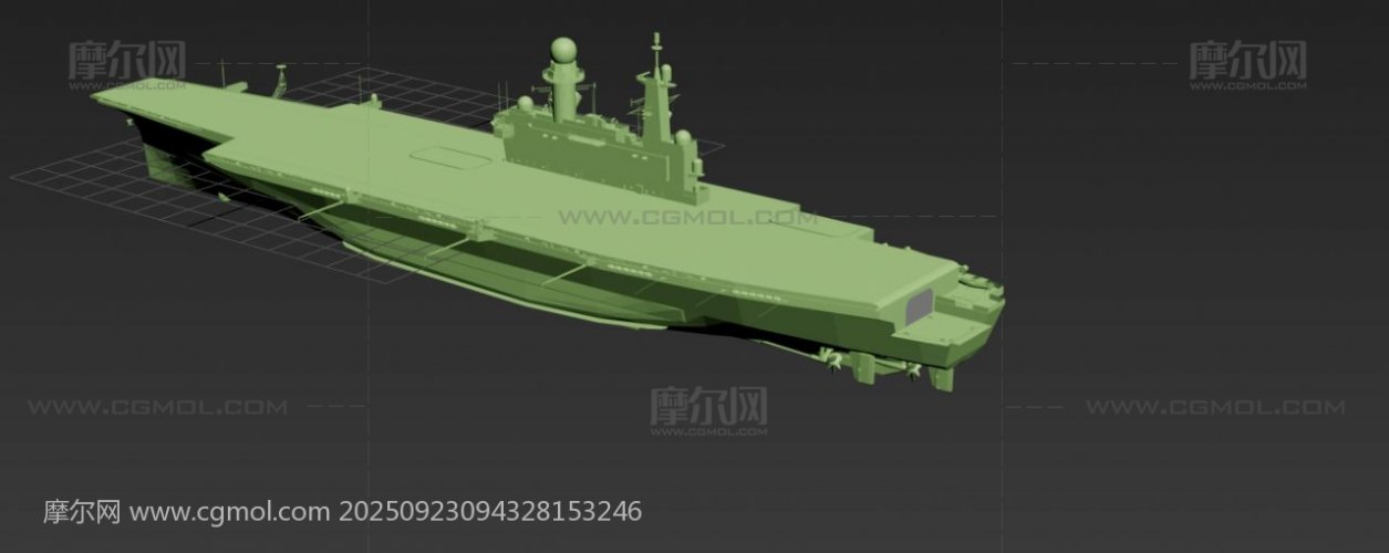
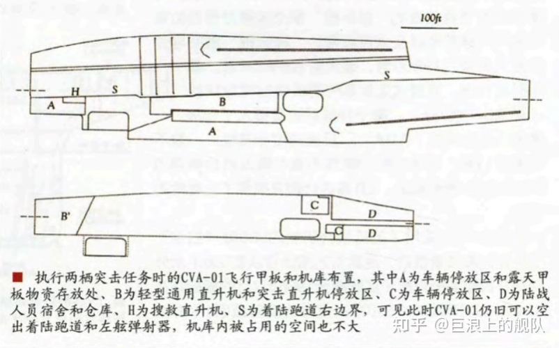
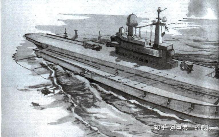
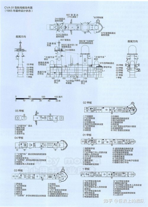
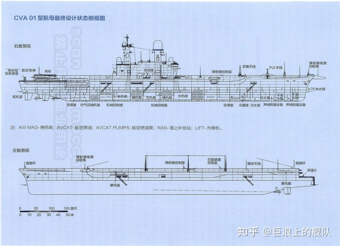
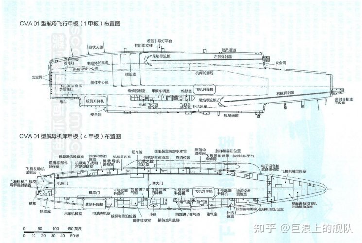
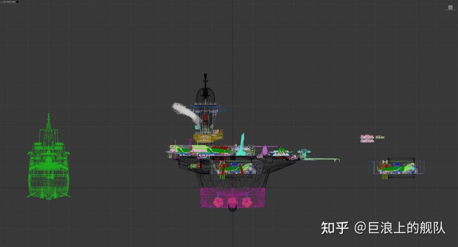
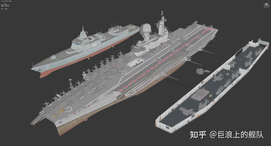
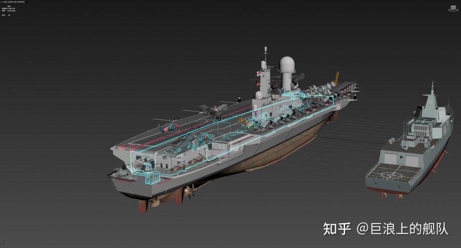
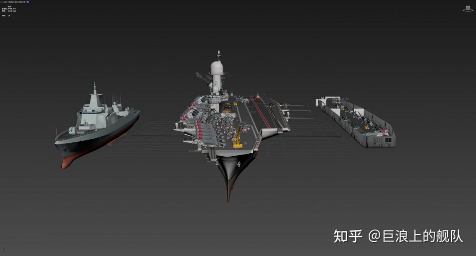
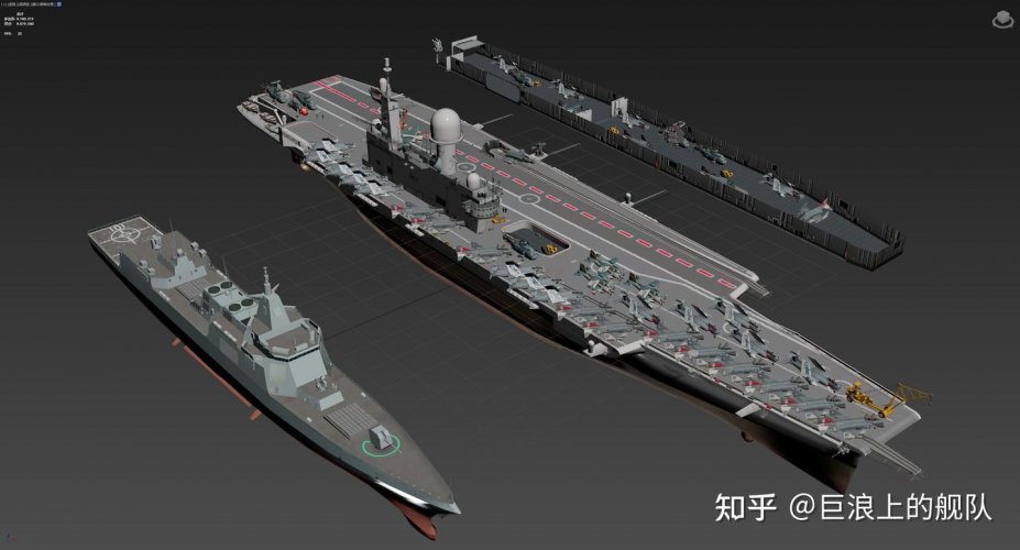
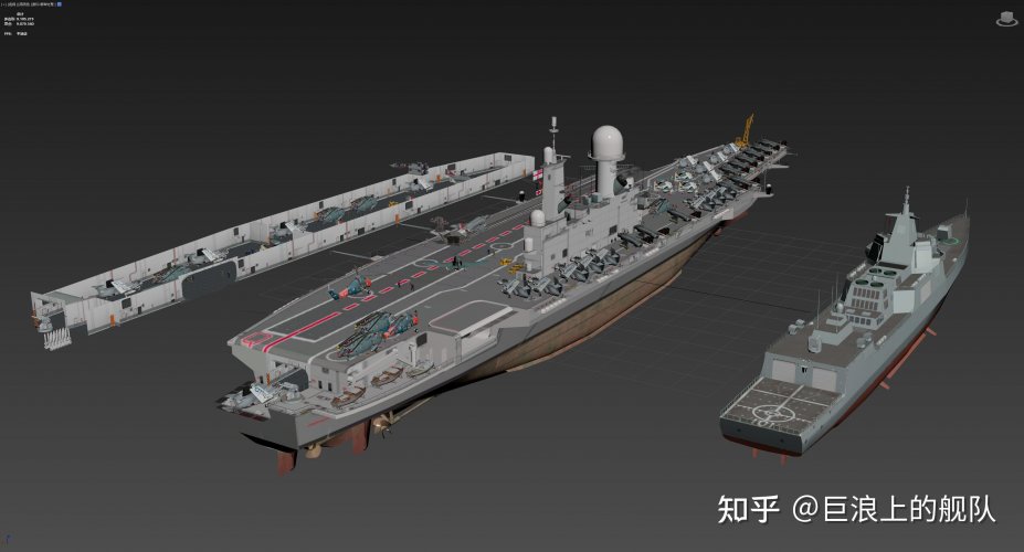
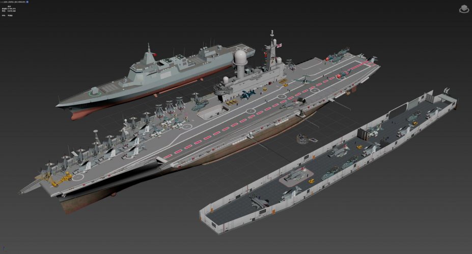
Some renders and plans from a Chinese post,
for archive purposes mainly.
for archive purposes mainly.
Attachments
-
 b_468617_19212556838544597.jpg143.6 KB · Views: 120
 -
 b_468617_1221407853854488.jpg112.9 KB · Views: 108
 -
 b_468617_7346978385459.jpg116.8 KB · Views: 101
 -
 b_468617_9752858103500886.jpeg103.8 KB · Views: 111
 -
 v2-89177c1ab77e07793f08dd3312166f9e_r.jpg52.5 KB · Views: 123
 -
 v2-d5885c8b6f5c718c1e7d824ece28daa6_1440w.jpg32.4 KB · Views: 125
 -
 v2-c75064e134c84d446dd9b6139c25a932_1440w.jpg70 KB · Views: 131
 -
 v2-79c62edda2bd7e00a777d2d644120361_1440w.jpg144.5 KB · Views: 133
 -
 v2-710a1d7739334a72d36b1c17861376af_1440w.jpg281.9 KB · Views: 133
 -
 v2-cb4b6ffcfc1a082580ca6b4098d021bc_1440w.jpg66.5 KB · Views: 133
 -
 v2-c77a0e1584fb6a4c39c64ea59ff85f6a_1440w.jpg209.6 KB · Views: 130
 -
 v2-5d8c7ab659cbbac884034063410c900c_r.jpg230.6 KB · Views: 127
 -
 v2-8915b5e0431287db7e0c87918a8b2d32_1440w.jpg68.5 KB · Views: 111
 -
 v2-b3e175990d88f26dda6cd70eee901beb_1440w.jpg102.6 KB · Views: 118
 -
 v2-3a54478acaf54a61c8cd72610b4103c1_1440w.jpg93.9 KB · Views: 118
 -
 v2-ad95e542314ae7437922249871289587_1440w.jpg74.9 KB · Views: 111
 -
 v2-fa5f38db6589e514a3ab9ccb8e48bec2_1440w.jpg55.1 KB · Views: 110
 -
 v2-ec659aa9aee0b413b95f62df0c5ff347_1440w.jpg96.3 KB · Views: 114
 -
 v2-887a6f47ed31e05021ed3ba8894b356d_r.jpg323.6 KB · Views: 115
 -
 v2-851dfc6968a6fa3c65df1ecf42dad3df_1440w.jpg95.6 KB · Views: 112
 -
 v2-ba61800cfa049cd032991a683a752e5b_1440w.jpg93 KB · Views: 120
Last edited:
apparition13
I really should change my personal text
- Joined
- 27 January 2017
- Messages
- 728
- Reaction score
- 1,342
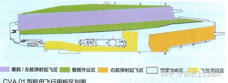
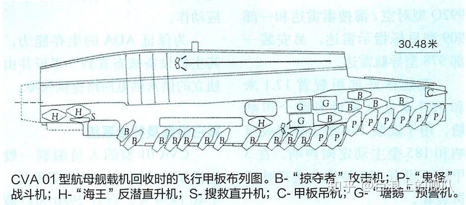
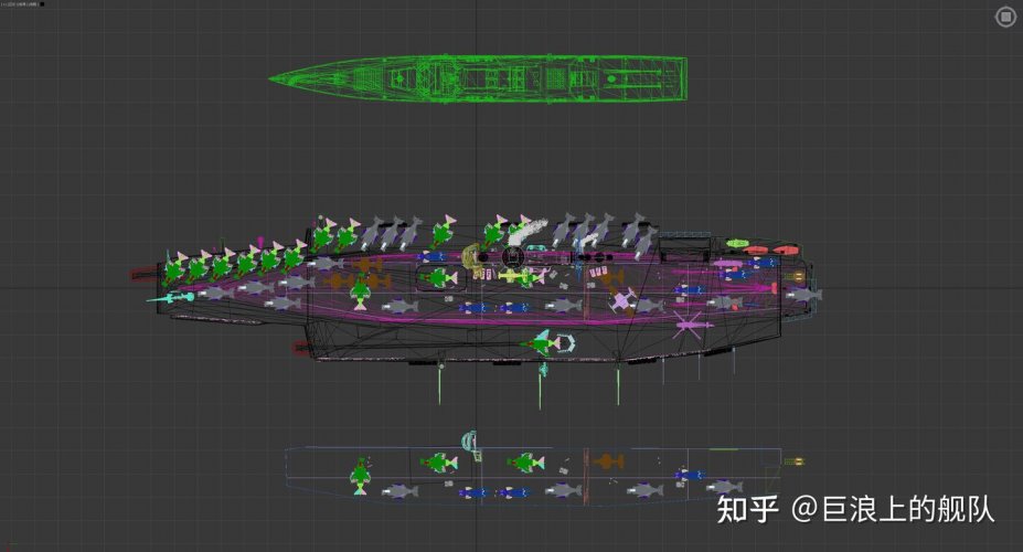
That deck park image looks wrong. The whole point of the design is to have three lanes, with a landing lane to the port, a launch lane to starboard, and a deck park lane centerline.Some renders and plans from a Chinese post,
for archive purposes mainly.
Aircraft should be parked on the centerline (and in the hangar), with the Alaska highway clear to run aircraft from the hangar and centerline deck park to the starboard catapult, which also needs to be clear for launches. The flow of aircraft is port (land) to center (park and move to hangar) to starboard (launch).
I think CVA-01 should have been larger, but given the constraints the genius of the design is how efficient aircraft movement is, and how that feeds into operational tempo.
We have no idea, unfortunately, when those plans (not renders, obviously) were made and what from. It very well may be something that the Chinese obtained at the time or somewhat later (60s-80s) or their speculation showing how they would've done it. Those plans are a kind of historical artifact in their own right.That deck park image looks wrong. The whole point of the design is to have three lanes, with a landing lane to the port, a launch lane to starboard, and a deck park lane centerline.
Aircraft should be parked on the centerline (and in the hangar), with the Alaska highway clear to run aircraft from the hangar and centerline deck park to the starboard catapult, which also needs to be clear for launches. The flow of aircraft is port (land) to center (park and move to hangar) to starboard (launch).
Last edited:
A Tentative Fleet Plan
I really should change my personal text
- Joined
- 9 April 2018
- Messages
- 1,356
- Reaction score
- 3,386
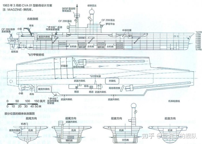
The plans are real, they are pirated from Ian Sturton's Warship 2014 article, which were drawn up in reference to archival material.We have no idea, unfortunately, when those plans (not renders, obviously) were made and what from. It very well may be something that the Chinese obtained at the time or somewhat later (60s-80s) or their speculation showing how they would've done it. Those plans are a kind of historical artifact in their own right.
Last edited:
Including the deck parking plan?Ian Sturton's Warship 2014 article
apparition13
I really should change my personal text
- Joined
- 27 January 2017
- Messages
- 728
- Reaction score
- 1,342
I just looked, yes, that image is from the article. It says it shows two-thirds of the air group with the other third presumably in the hangar. Two Buccaneers and ten phantoms are missing, so they must be inside. It's a confusing image though, since it looks like the only way to use the Alaska highway operationally is if a third of the aircraft are airborne. Which makes me reconsider my previous statement.Including the deck parking plan?
So it's at least one of the original arrangements.I just looked, yes, that image is from the article.
And I did think for a moment that these may be a part of the early Chinese carrier studies, when they considered all kinds of foreign examples.
Last edited:
The whole point of the design is to have three lanes, with a landing lane to the port, a launch lane to starboard, and a deck park lane centerline.
Aircraft should be parked on the centerline (and in the hangar), with the Alaska highway clear to run aircraft from the hangar and centerline deck park to the starboard catapult, which also needs to be clear for launches. The flow of aircraft is port (land) to center (park and move to hangar) to starboard (launch).
I think CVA-01 should have been larger, but given the constraints the genius of the design is how efficient aircraft movement is, and how that feeds into operational tempo.
it looks like the only way to use the Alaska highway operationally is if a third of the aircraft are airborne. Which makes me reconsider my previous statement.
That’s what’s always confused me about CVA-01’s deck layout. It seems hyper optimized to optimize deck flow to the catapults during cyclic operations with only but at the expense of everything else since the deck park is small.
This limits the number of aircraft that can be efficiently launched and recovered each cycle and overall air group size. It would never work for a traditional USN air wing. Just about the only rationale for CVA-01’s layout is if you are doing away with cyclic operations and launching & receiving small packets of aircraft on a continuous basis.
Scott Kenny
ACCESS: USAP
- Joined
- 15 May 2023
- Messages
- 17,024
- Reaction score
- 24,159
Which does work for day-to-day ASW and BARCAP missions, plus CAS in colonial interventions.Just about the only rationale for CVA-01’s layout is if you are doing away with cyclic operations and launching & receiving small packets of aircraft on a continuous basis.
It would be worthwhile that someone check the width of the deck, to starboard of the island. The reason to check this is that RN aircraft like the Bucaneer and the Scimitar had widths of just under 20 feet, when folded. In contrast the US Phantom was almost 28 feet when folded, because only the outer part of the wings folded. This may have constrained CVA-01 deck ops, when the air group adopted Phantoms as it's fighter. Early illustrations aluded to SR-177 as the fighter, but this was skinnier that the Scimitar. I'd also suggest that the phrase 'Alaskan highway' only came later on, as it was the coloquial description of the structure added to HMS Eagle outboard of the island, but this wasn't wide enough for aircraft, unlike the parallel deck intended for CVA-01.
Last edited:
- Joined
- 6 September 2006
- Messages
- 5,201
- Reaction score
- 11,120
I estimate the 'Alaskan Highway' to be about 34ft wide, with around 18ft from the centreline to the edge of the island.
So you could - in theory - just about squeeze an F-111B onto it (~33ft).
Most of the OR.346/OR.356 designs came in around 27-31ft, while BAC Type 583V was smallest at 25ft. Ironically the VG Lightning at 36ft 7in would be pushing the limit.
Likewise I estimate the four weapons lifts serving the 'Highway' could accommodate four 65-70ft long aircraft - again tallying with the Bucc and the OR.346/OR.356 designs. The Highway's effective length is around 300ft.
There were only two pressure refuelling stations though located mid-Highway (between weapon lifts 2 & 3), so it was optimised for rapid reloading over rapid refuelling. But with a rolling 'line' of aircraft (given they can only take-off from one bow cat) it would still have been a pretty smooth rolling assembly line-like process.
Hood. Interesting details. With the rearming station partway up the highway, and the aircraft still folded, this would be a constraint, i. e. you could only rearm centre line weapons, not those on outer wing pylons.
Scott Kenny
ACCESS: USAP
- Joined
- 15 May 2023
- Messages
- 17,024
- Reaction score
- 24,159
Also, remember that you can hang a wing over the edge for a bit of clearance. Your safe limit is the landing gear!I estimate the 'Alaskan Highway' to be about 34ft wide, with around 18ft from the centreline to the edge of the island.
So you could - in theory - just about squeeze an F-111B onto it (~33ft).
Most of the OR.346/OR.356 designs came in around 27-31ft, while BAC Type 583V was smallest at 25ft. Ironically the VG Lightning at 36ft 7in would be pushing the limit.
Likewise I estimate the four weapons lifts serving the 'Highway' could accommodate four 65-70ft long aircraft - again tallying with the Bucc and the OR.346/OR.356 designs. The Highway's effective length is around 300ft.
There were only two pressure refuelling stations though located mid-Highway (between weapon lifts 2 & 3), so it was optimised for rapid reloading over rapid refuelling. But with a rolling 'line' of aircraft (given they can only take-off from one bow cat) it would still have been a pretty smooth rolling assembly line-like process.
apparition13
I really should change my personal text
- Joined
- 27 January 2017
- Messages
- 728
- Reaction score
- 1,342
I'd hope there is a curb/kerb on the edge then. I've bumped a fair few, I'd hate to do a "whoops-a-daisy" into the drink.Also, remember that you can hang a wing over the edge for a bit of clearance. Your safe limit is the landing gear!

- Joined
- 6 September 2006
- Messages
- 5,201
- Reaction score
- 11,120
The only aircraft of the Sea Vixen-Bucc-Phantom trio with hardpoints on the outer wings is the Bucc with (pair inboard, pair outboard).Hood. Interesting details. With the rearming station partway up the highway, and the aircraft still folded, this would be a constraint, i. e. you could only rearm centre line weapons, not those on outer wing pylons.
The OR.346 designs all had weapon bays for their proposed long-range AAMs or nuclear strike loads and the OR.356 were mostly VG-winged so had most of their armament mounted ventrally. The diminutive P.1154 'Big Wing' was only 22ft folded and all the hardpoints were within that envelope.
So the constraint mainly applies to the Bucc, especially as the accessible inboard pair were normally occupied by external fuel tanks. But there is enough deck space at the forward weapon elevator position to load a spread-winged Bucc to partially overcome that issue.
The Sea Vixen also had a hard point each side outboard of the wing fold. Usually seen carrying a drop tank. There were also two inboard on each wing.
 www.gettyimages.co.uk
Getty Images
Getty Images UK. Find high resolution royalty-free images, editorial stock photos, vector art, video footage clips and stock music licensing at the richest image search photo library online.
- Joined
- 22 April 2012
- Messages
- 2,267
- Reaction score
- 2,744
Abbreviated version of early CVA-01 aircraft size considerations: There were a series of future aircraft studies through the late 1950s, including a diversion into Douglas F6D equivalents, that ultimately culminated in the Vickers Type 581 to OR.346. Other designs were looked at, such as the DH.127, but the Navy's study work focussed on the Type 581. Variable-geometry (VG) was seen as the solution to providing the loiter and speed performance the Navy wanted. Combined with lift jets it was believed VG would also deliver the 80 knot landing speed the Navy were after. It was intended to provide a common airframe for both strike and fighter roles, studies assumed grandfathering in an improved (lightened) version of the TSR-2 nav-attack system for strike and development of a new AI radar and missiles (see here) for the fighter mission. The Navy had a costed plan to run a development and procurement programme through the 1960s. The Type 581 is the canonical Navy only (despite early RAF involvement) OR.346. This work set the following dimensions:
Span: 70ft (30ft folded)
Length: 70ft (64ft folded)
Height: 23ft (19.5ft folded)
Actual detailed design of the carrier produced a lower hangar height and other detail changes with various small fluctuations right up to the end.
The later OR.346 designs were an attempt to meet a combined RN/RAF requirement created by the edict that all future aircraft would be common to both services and should, I think, be considered separately. OR.346/355 was the programme intended to follow the P.1154. Both services saw it as a replacement for their entire inventory at various times. The RAF's starting point was OR.355 which might be the maddest Operational Requirement that service ever produced, think SR-71 performance but V/STOL and with Missileer style radar and AAMs. Despite creating a lot animosity between the services it didn't last very long.
- Joined
- 6 June 2006
- Messages
- 14,669
- Reaction score
- 20,614
Link to the old website Navy-matters : the CVA-01 entry.