When the USSR revealed the MiG-15, during the May 1949 parade, Western analysts noted that it strongly resembled the German Focke-Wulf Ta 183 A-0 jet fighter project.
Many Western books and magazine articles stressed the similarity of both designs and they assumed that the general aerodynamic layout of the MiG was influenced by German designs.
Perhaps the Soviets had continued to develop the Ta 183 after the war, as they did with the Junkers Ju 248, EF 126, EF 127, EF 131, DFS 346 and the Heinkel He 343/Ilyushin Il-22 projects.
Why not?
The USSR was within its rights to use the technology conquered with the sacrifice of its soldiers.
The importance of the German scientific and technological achievements was well understood both in the USSR and in other countries.
After the war ended, the Allied powers raced to seize aeronautic technology in occupied Germany and the aerodynamic configuration of these German projects, proof-of-concept prototypes, weapons, and operational airplanes were used in the first generation of the Cold War jet fighters.
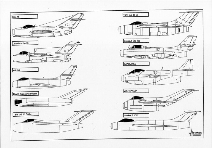
The nose air intake/tubular fuselage/rear swept wings and tail surfaces configuration of the Messerschmitt P.1101 and Focke-Wulf Ta 183 fighters were used in North American F-86
Sabre, MiG-15
Fagot, MiG-17
Fresco, Lavochkin La-15
Fantail, Dassault MD 450
Ouragan, Dassault MD 452
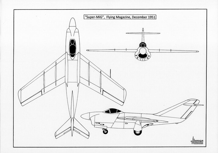
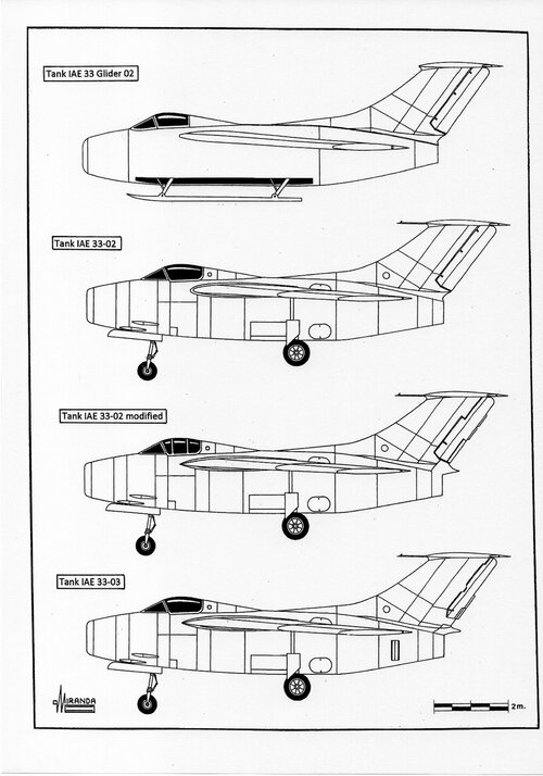
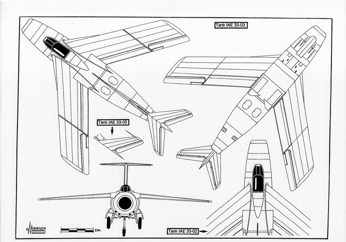
Mystère, Nord 2200, Tank IAE 33
Pulqui II, Fiat G.91
Gina and Fuji T-1.
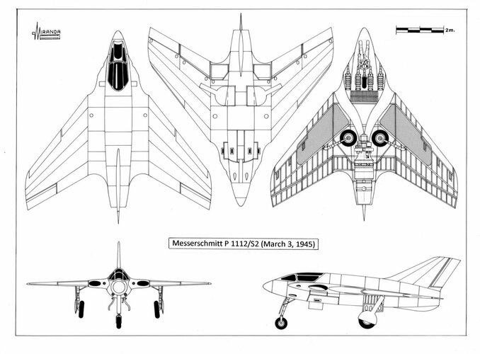
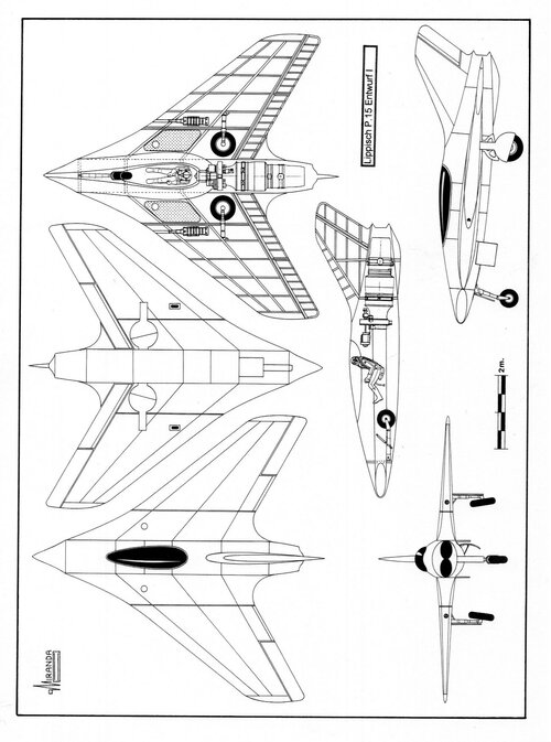
The delta wing configuration of Lippisch DM-1 and Messerschmitt P.1112/S2 was used in the Convair XF-92, Convair F-102, Nord 1402
Gerfaut, Sud-Est S.E. 212
Durandal, Dassault
Mirage I, Avro 707, Boulton Paul P.111, Boulton Paul P.120, Handley Page H.P.115, Fairey
Delta 1, Fairey
Delta 2, BAC 221 and Short SC.1.
The maximum speed of the first prototypes XF-92 and YF-102 was limited to 0.98 Mach, due a transonic drag much higher than expected, but the problem was solved in December 1954 using the aerodynamic principle named
area rule, patented by Junkers on March 1944.
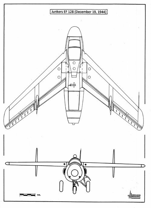
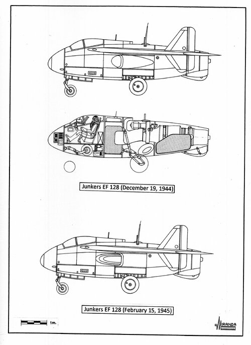
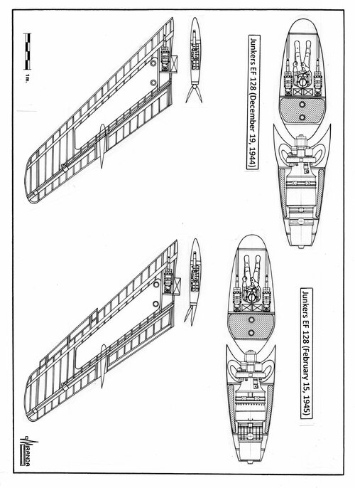
Swept wings with two trailing-edge fins configuration from Arado E.583 and Junkers EF.128 projects was used in the Chance Vought F7U
Cutlass naval fighter.
The “bat wing” of the Messerschmitt Me P.1109-01 and Blohm und Voss P.208 projects was used in 1996 in the prototype Boeing
Bird of Prey.
The oblique
scissors wing of the Messerschmitt Me P.1109-01 and Blohm und Voss P.202 projects were flight tested in 1979 with the NASA Ames AD-1 research airplane.
The forward-swept wing of the German projects Heinkel He 162 B, Blohm und Voss P.209.02, BMW
Strahlbomber II, and Focke-Wulf P. 03028, was flight tested with the Grumman X-29 research plane in 1984.
The butterfly tailplane of the Heinkel P.1079A and Messerschmitt P.1110 projects were used in 1951 in the Supermarine Type 508 prototype and in the Fouga CM.170
Magister jet trainer in 1952.
The
Versuchsflugel II crescent wing of the Arado Ar 234 V16 project was used in the Handley Page H.P.88 research plane in 1951 and in the Handley Page
Victor strategic bomber in 1952.
The tailless configuration of the Messerschmitt Me 163
Komet was flight tested in the research planes de Havilland D.H.108 in 1946, Northrop X-4 in 1948, Payen
Katy in 1954 and in the Douglas F4D
Skyray naval fighter in 1951.
The double-delta configuration of the Henschel P.130 project was used by SAAB in their J35
Draken jet interceptor in 1955.
The jet/rocket mixed propulsion system of the Messerschmitt prototype Me 262 V074 and the Focke-Wulf Projekt VI
Flitzer were used in the French interceptor Dassault
Mirage IIIC in 1961 and in the British research airplane Saunders-Roe S.R. 177 in 1947.
The variable-geometry wing of the Messerschmitt P.1102-05 was used in the Bell X-5 and
Mirage G prototypes, in the Grumman F-14
Tomcat naval fighter, in the MiG-23 fighter-bomber and in the Panavia
Tornado bomber.
The radar rotating antenna of the airborne early warning airplanes Grumman E-2
Hawkeye and the AWACS Boeing E-3
Sentry, was developed in 1944 for the Arado Ar 234 C-3, to track a bomber stream up to distances of 45 km, using a FuG 244
Bremen 0 radar set with a rotating disc above the fuselage.
The heat-seeking missile AIM-9
Sidewinder and the Soviet copy R-13/AA-2
Atoll were based on the infrared homing devices and infrared proximity fuses developed by AEG and Kepka for the German missiles Messerschmitt
Enzian, Henschel Hs 117
Schmetterling, EMW
Wasserfall and Ruhrstahl-Kramer X-7
Rotkäppchen.
The annular wing developed by von Zborowski for the Heinkel
Wespe VTOL project, was flight tested in 1958 with the French prototype SNECMA
Coléoptère.
The French DEFA and British ADEN 30 mm cannon were developed from the German Mauser MG 213C.
The USAAF 0.60-caliber heavy machine gun was a straight copy of the German Mauser MG151.
The
Mighty Mouse air-to-air unguided rockets fired by the all-weather interceptors Lockheed F-94
Starfire, Northrop F-89
Scorpion and North American F-86 D
Sabre Dog during the Cold War, were developed from the Rheinmetall R4M
Orkan 55 mm rocket, and their automatic firing radar system probably was a development of the German FuG 222
Pauke S fire control radar with
Oberon-Elfe predictor system.
The ramjet propulsion of the German projects Lippisch P.13a, Skoda-Kauba SK P.12, Heinkel P.1080, Focke-Wulf Ta 283 and Messerschmitt P.1101L was flight tested by the North American F-51D c/n 44-63528 in 1946, the Lockheed F-80
Trijet in 1948, and the French prototypes Leduc 021 and Sud-Ouest SO 9000
Trident in 1953.
The turboprop configuration of the Focke-Wulf P.0310226-17 project was flight tested in 1953 with the McDonnell XF-88B prototype, and by the Republic XF-84 H
Thunderscreech research plane in 1955.
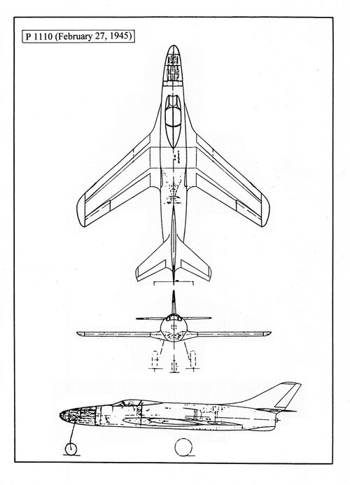
The canard fore planes of the Blohm und Voss P.217 and Messerschmitt P.1110 (Feb 12, 1945) projects were used by the Dassault
Mirage Milan in 1969.
Several versions of the Fieseler Fi 103 (V-1) cruise missile were manufactured in USA, as Republic-Ford JB-2
Loon, in France as ARSAERO CT-10 and in the USSR as the Izdeliye 10.
The EMW V-2 ballistic missile was manufactured in the USSR as the R-1 in 1948, in USA as RTV-G-4
Bumper and developed as the PGM
Redstone rocket of the NASA
Mercury project in 1958.
The Rheinmetall-Borsig
Rheintochter surface-to-air missile concept inspired the Soviet SA-2 (1958) and the US
Nike Ajax (1954).
The Doblhoff WNF 342 jet propelled rotor concept was used in the Hiller YH-32
Hornet helicopter in 1950, in the XH-26
Jet Jeep helicopter in 1952, in the Fairey
Rotodyne compound gyroplane in 1957 and in the Fairey
Gyrodyne prototype in 1957.
The SNECMA
Atar 101 French turbojet was developed from the BMW 003 axial-flow turbojet.
However, the MiG-15 seems to be a special case. Over the past 72 years respected authors have published numerous works denying the Focke-Wulf heritage of the Soviet fighter and detailing the differences between the two designs.
They are certainly right about the Ta 183 A-0
Huckebein, which is the version best known for having won the
Jägernottprogramm contest.
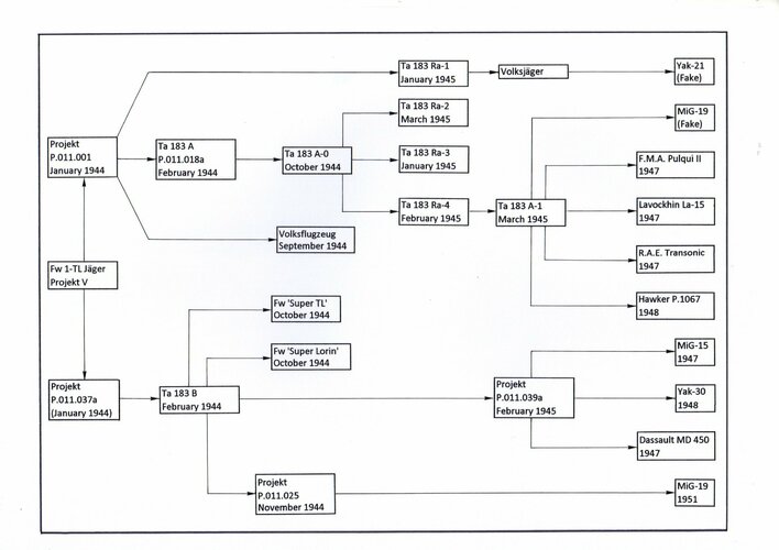
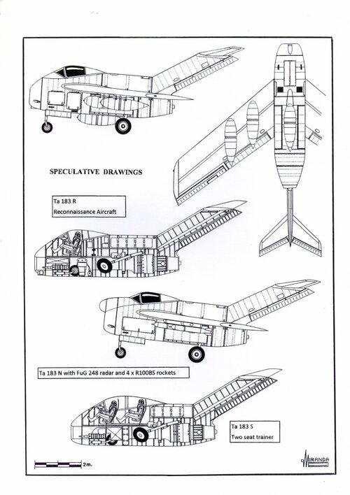
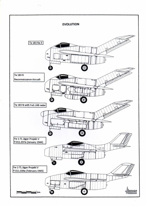
But the information captured in Berlin about the latest projects of the Bad Eilsen design team comprised eleven variants of the Ta 183 and nine scaled-up and scaled-down associated designs that shared the original basic aerodynamic layout.
These projects differed in the position of the wings (shoulder, mid and low) and tail planes (T, mid and low), had different wings with swept angles between 33 and 43 degrees, tail planes between 35 and 49 degrees swept, and tailfins between 41 and 67 degrees swept, at the leading edge in all cases. Most were equipped with fuselage retractable landing gear, but some retracted on the wings, such as the MiG-15.
The Soviet designers were able to adopt ideas from all of them by concentrating them in a single project.
The fuselage of the MiG-15 (built with
Podberezhye semi-monocoque Duralumin structure) and the pressurized cockpit were both based on those of the Junkers Ju 248 V2 captured at Kassel and the ejector seat was based on that of the Heinkel He 162 A-2 captured in Vienna.
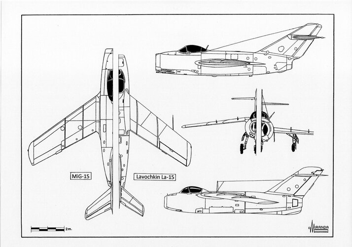
The wings were a modification of those of the Lavochkin La-160, which were in turn based on those of the Focke-Wulf designs captured in Berlin by the People's Commisariat of the Aviation Industry, and joined the fuselage in the same position as those of the Junkers Ju 248 V2.
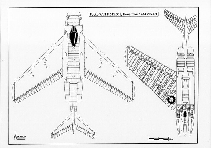
The wing retractable undercarriage and the 45-degree swept tailplane were very similar to those of project Focke-Wulf P.011.025 (November 1944).
The engine was a British design.
But, according to the Soviet designers, the MiG-15 was an indigenous design.
This is true in the sense that they had been able to integrate different German and British technologies into a design adapted to the Soviet manufacturing standards and that no German TsAGI technicians had been involved in this process.
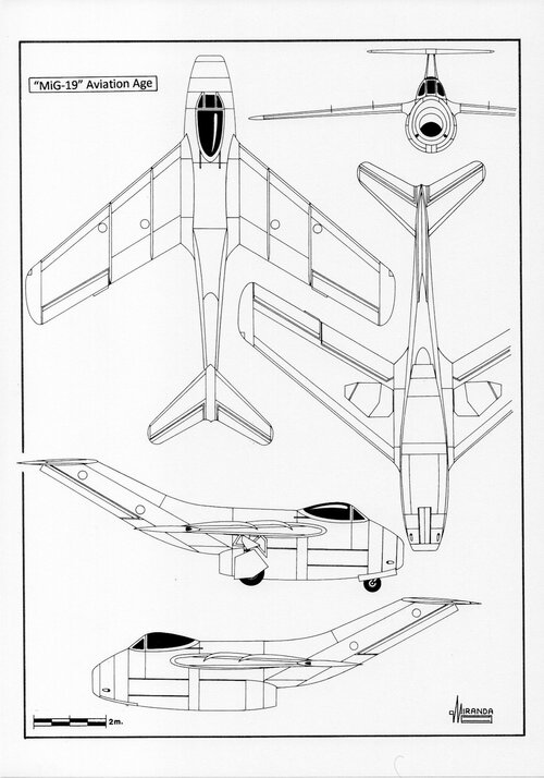
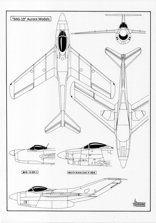
Ironically, the MiG OKB designers used Focke-Wulf T-tail planes on the MiG I-270 rocket fighter prototype and in the MiG-19 prototype SM-2/1, without success.
On July 15, 1944, the
Luftwaffe Technisches Amt (Technical Office) requested through
Proposal 222/I the design of an air superiority fighter, powered by a Heinkel HeS 011 A-0 turbojet, as part of the
Jägernottprogramm (emergency fighter program) contest.
The new aircraft should reach a maximum speed of 1,000 km/h at 7,000 m, with a service ceiling of 14,000 m, an armament of two MK 108/30 heavy cannons with 60 rounds per gun and a fuel capacity of 1,000 liters. A high proportion of
sparstoffe (non-strategic materials), such as steel, wood, and plastics, would be used for its construction.
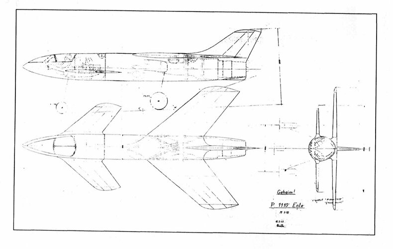
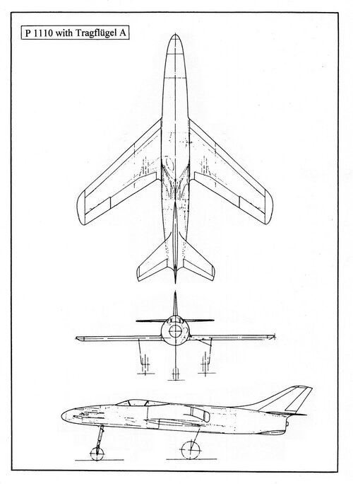
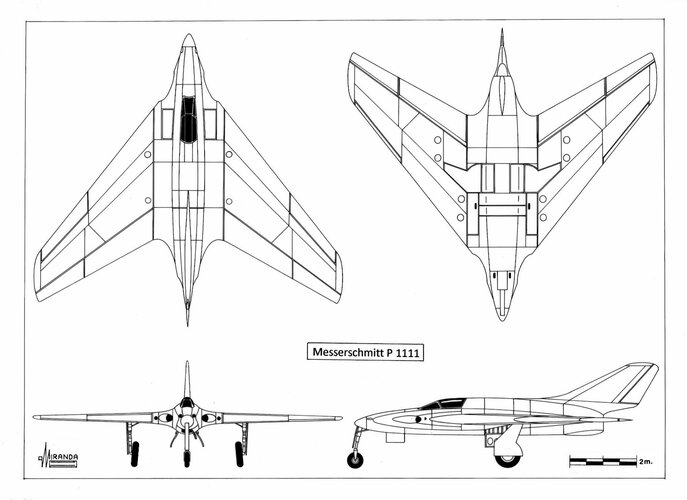
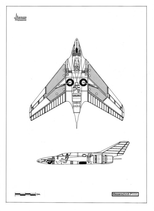
The OKL ordered that large-scale production should start in February 1945 and reached a monthly production rate of 5,000 fighters in June. Initially the projects presented were the Blohm und Voss P.213.03, Heinkel P.1078 C, Junkers EF.128, Messerschmitt P.1101, P.1110/I and P.1111, as well as the Focke-Wulf Ta 183 A, Ta 183 B and
Flitzer III.
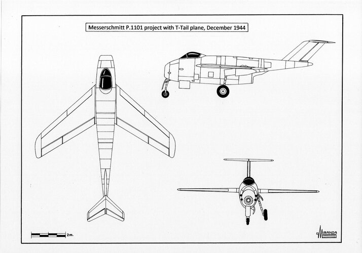
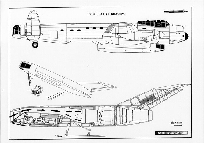
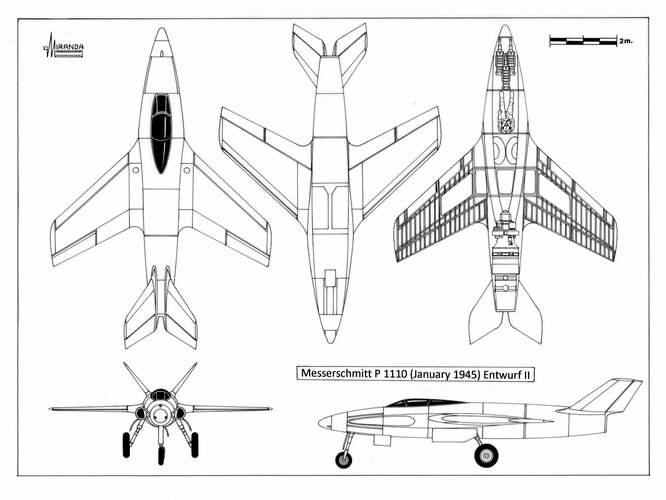
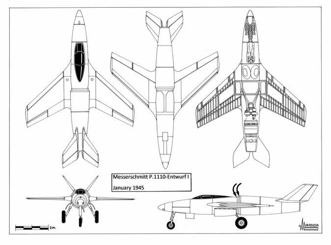
In October 1944 only two contestants remained: the Focke-Wulf Ta 183 A and the Messerschmitt P.1101, a pod-and-boom design theoretically capable of reaching transonic speed during combat diving without losing maneuverability. But the wind tunnel tests performed by the AVA-Göttingen institute during the autumn of 1944, with P.1101 scale models, revealed that the maximum speed would still be below their expectations.
The reason was the turbulence generated in the joint of the rear fuselage and the engine nacelle, that had an '8' shaped section. It was discovered that the airframe generated a triple shock wave at transonic speed. The first one was formed around the cockpit hood, the second over the wing and the third one over the tailplane. The shock waves overlapped among each other with a braking effect like that of an arrow going through three disks of felt launched in the air.
The Messerschmitt designers tried to solve the problem replacing the cockpit hood with another of low drag, type
Rennkabine, originally designed for a high-speed version of the Me 262. Wind tunnel tests performed with 'V' and 'T' shaped tail planes revealed that such modifications did not substantially improve aerodynamic performance and the P.1101 was cancelled at the end of 1944.
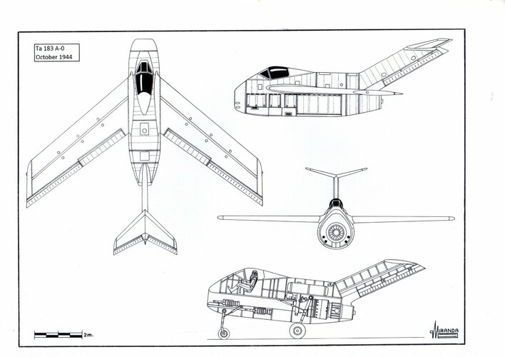
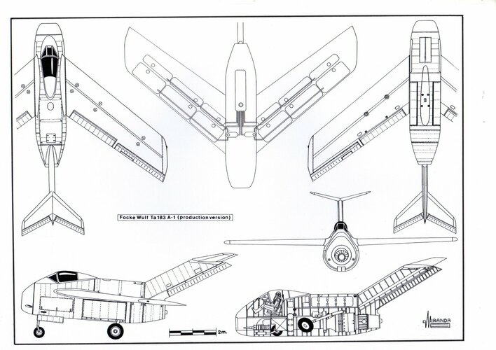
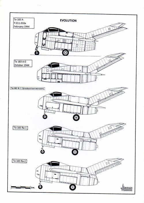
During the selection process, the Ta 183 A suffered numerous modifications that gave way to the Ta 183 A-0 version, winner of the contest. The wing chord was reduced from 252 to 235 cm and the wing area to 22.5 sq. m. The tailfin swept was of 60-degrees, the overall length of 9.2 m and the height of 3.5 m. The tailplane sweep angle was increased to 45-degrees and the ground incidence to 7-degrees.
The estimated maximum speed for this version was set at 960 km/h and the service ceiling at 14,400 m, with an initial climb rate of 20 m/sec.
The
Technisches Amt considered that the 40-degree (25% chord) swept wings of the Ta 183 were potentially dangerous during landing at low speeds. But most of the criticism of its experts were directed against the T-tail plane configuration. They argued that it was too heavy for a fighter, it did not provide enough lateral stability and could not be built on wood.
The T-tail plane was also too advanced for the mentality of the OKL (
Oberkommando der Luftwaffe-Air Command). Its main objection was based on the danger posed by the tailplane to a pilot attempting to bail out at high speed.
The ejector seat designed in 1942, to equip future versions of the Focke-Wulf Fw 190 piston fighter, could launch the pilot at a height of 2 m above the cockpit floor, with a margin of 43 cm over the tailfin. But the T-tail plane, designed to avoid the turbulent airflow generated by the cockpit hood at transonic speeds, had to be installed more than three meters high above the level of the cockpit floor to be effective.
The
Technisches Amt calculated that during an ejection at critical Mach number, the T-tailplane would reach the pilot in only 0.018 seconds. In 1944, the most effective ejector seat of the world was the
Heinkel Kartusche propelled by an explosive cartridge with 30 grams of powder, with an ejection speed of 11 m/sec and 12 g. It was designed for speeds not exceeding 700 km/h. At 1,000 km/h and using a T-tail plane it was necessary to increase the ejection speed to 200 g, with equally lethal effects for the pilot.
Coming ahead of the predictable objections of the
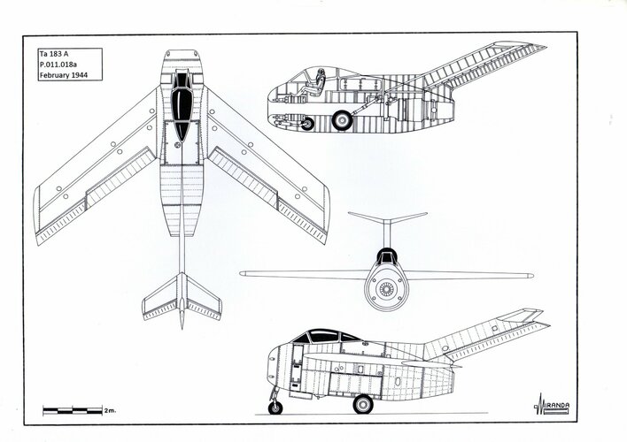
Technisches Amt, Kurt Tank designed a more conservative version as well, with reduced armament and a conventional tailplane. This new configuration, described in the dossier
Baubeschreibung Nr.252, was presented to the OKL at the same time than the project P.011.018a to avoid the total rejection of the project. Both designs received the official designation Ta 183, been described in the specialized literature as Ta 183-I/Ta 183 A and as Ta 183-II/Ta 183 B.
In February of 1944 Kurt Tank sent to the RLM (
Reichsluftfahrtministerium – Reich Ministry of Aviation) a set of drawings and calculations contained in the dossier denominated
Baubeschreibung Nr.252 describing a ‘soft’ second iteration of the Ta 183, denominated Ta 183 B (P.011.037a).
The cross section of the fuselage was 24 per cent lower than that of the Ta 183 A, the armament was reduced to only two MK 108/30, the cockpit was moved backwards 1.5 m and the tail plane was placed at the same height as the head of the pilot. The wingspan was reduced by 50 cm and the sweep wing angle to 34-degree, the wing roots were moved to the rear by 90 cm and the tailplane was moved forward by 72 cm. The internal fuel capacity did not change.
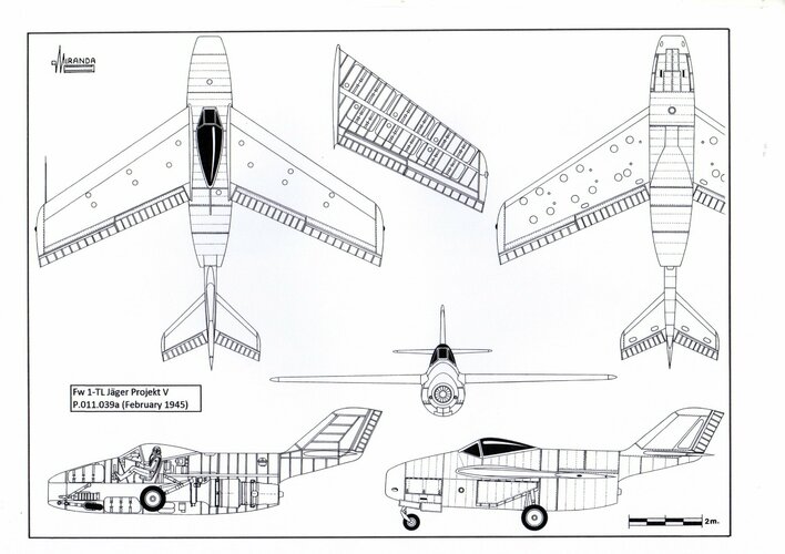
This basic design evolved throughout 1944 trying to adapt to the changing demands of the
Jägernottprogramm. In its version P.011.039a (February 1945) the cockpit had been advanced 36 cm to improve the visibility of the pilot at landing, the wings had been advanced 11 cm to preserve the longitudinal stability, altered by the weight of the new fuel tank of 250 liters installed over the air duct.
The Ta 183 B was superior to all versions of the Ta 183 A in ceiling and maximum speed, thanks to its smaller front section and the lower structural weight of the airframe and surely this information was obtained by MiG designers through the captured German scientists.
When the MiG OKB won the March 11, 1947 fighter contest, the MiG-15 production had priority to receive the most powerful RD-45 turbojet (the Soviet version of the Rolls-Royce
Nene Mk.I).
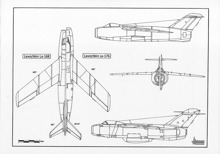
The Lavochkin bureau stopped the La-168 development to concentrate their efforts in the design of the La-174, a new fighter that was 340 kg less heavy than the MiG and that would be powered by the less powerful RD-500 turbojet (Soviet version of the Rolls-Royce
Derwent V).
The La-174 was a 90% scaled down version of the La-168 and it had no relation to the La-174 TK straight wing prototype.
The aircraft was flown on January 8, 1948, suffering dangerous tailplane flutter and crashed during testing on May 11, 1948.
The defect was corrected in the second prototype La-174D that flew on June 12, 1948.
Combats tests performed in the Tshkalovsk research center proved that the La-174D was superior to the MiG-15 in maneuverability, because its lower weight and excellent wing design compensated for the turbojet's lack of power.
In September 1948 the new fighter was accepted for production, alongside the MiG-15, and officially named Lavochkin La-15 in April 1949.
Operational tests with the 192nd IAP began in May 1949, at Kubinka-Moscow, but the unreliable hydraulic system resulted in undercarriage failures and landing crashes due to the extremely narrow track (1.70 m) of its landing gear.
The VVS had already had problems in 1943 with the landing instability of their
Spitfires on rough-field operations and the frequent crashes of the La-15 at side wind were considered unacceptable for a front-line fighter.
Only 235 La-15 fighters were built between December 1948 and August 1949.
The shoulder mounted La-15 wings (with 37º 20’ swept, 25 % chord, 12% thickness, 6º anhedral and smaller span-chord ratio than those of the MiG) were based on those of the La-160. They were more resistant and rigid because they were not designed to accommodate the main undercarriage legs.
But the La-15 wings were more complex to produce, and their light airframe was not sturdy enough to withstand the recoil of a 37 mm cannon.
The more rugged design of the MiG-15 was cheaper and easier to produce.
If the La-15 had been used in Korea against the F-86 fighters it would surely have been more successful in dogfight than the MiG-15, but most Russian historians deny the La-15's involvement in the war.
On the contrary, there are reports in the CIA Current Intelligence Bulletin of multiple sightings of jet fighters with shoulder-mounted wings.
These aircraft were seen by American and British pilots of F-86E, B-26, RF-80 and F-51 aircraft of the UN forces in Korea.
Pilots believed it was a new type of MiG and referred to it in reports as “MiG-17” or “Type-15”.
In late March 1952 a “Type 15” was observed only 100 feet away by the pilot of an F-86E of 4th FIG, 335th FIS. (Report of Lt. James D. Carey published in Time Magazine on March 13, 1952).
According with the CIA-FOIA files and with the reports of the UN pilots, the “Type 15” was sighted 14 times, engaged 10 times, two aircraft were destroyed and 11 damaged.
According to the article published by V. Ilyin, V. Rudyenko and J. Martinek in the Czech magazine Zlinek (Nº 14, vol. 2, 1994) a VVS Fighter Regiment, with twenty-two La-15 airplanes, carried out combat operations in Korea suffering four crashes due to the poor condition of the airfield. The other machines were sent back to the USSR.
Additional information from the specialized authors Mikhail Zhikorov, Warren Thompson and Larry Davis were published at “Wings of Fame” (Volume 1, 1995) and
http://sovietwarplanes.com/board/index.php?topic=1534.0
https://www.aereimilitari.org/forum/topic/9275-lavochkin-la-15-in-corea/
http://sabre-pilots.org/classics/v133duck.htm
http://www.foia.cia.gov/
It is strange that the Soviets did not attempt to use the La-15 against the UN
Sabres when the MiG-15s began to be systematically destroyed because of their inferior maneuverability.
So, what is the truth?
Lavochkin La-15
Fantail technical data
Power plant: one Klimov RD-500 turbojet rated at 1,590 kg thrust, wingspan: 28.9 ft. (8.83 m), length: 31.3 ft. (9.56 m), height: 12.8 ft. (3.9 m), wing surface: 179.6 sq. ft. (16.16 sq. m.), take-off weight: 8,500 lb. (3,850 kg), max speed: 638 mph (1,026 km/h), ceiling: 44,280 ft. (13,500 m), armament: three 23 mm NR-23 cannon, equipment: pressurized cockpit with (German) ultraviolet illumination of the instrument panel, ASP-1N gyroscopic gunsight (direct copy of the British Mk.IID), KUS-1200 speedometer, M-46 Machmeter, V-15 altimeter, RSI-6K R/T, S-13 gun camera and ejector seat.
To test the limits of the La-168 aerodynamic configuration, the La-176 prototype was built during the summer of 1948.
The new airplane was flown on September 22, 1948, fitted with 45-degree swept wings (25% chord) and three fences in each wing, reaching Mach 0.98 top speed only.
The RD-45 was replaced by a Klimov VK-1 (the Soviet version of the Rolls-Royce
Nene Mk.2) with 2,700 kg thrust.
On December 26, 1948, the La-176 exceeded the speed of sound diving from 39,360 ft. (12,000 m) over the Black Sea.
On February 3, 1949, the prototype disintegrated in flight when the canopy locks failed near Mach 1.
Lavochkin La-176 technical data
Power plant: one Klimov VK-1 turbojet rated at 2,700 kg thrust, wingspan: 28 ft. (8.59 m), length: 36 ft. (10.97 m), wing surface: 203 sq. ft. (18.25sq. m.), take-off weight: 10,209 lb. (4,631 kg), max speed: Mach 1.021, ceiling: 49,200 ft. (15,000 m).

")