Wow. Just wow. My own take at the row, right of the picture
- the red one with the tanks ontop, yes, looks like Grumman "intermediate external tank" design of mid-1971
- the ones below
They indeed look like iterations of MSC-036 to MSC-042 series, starting in August 1971 with 036.
That string of Shuttle Orbiter design iterations (as shown in Dennis Jenkins Shuttle magnum opus books ) has long fascinated me.
Because this was the exact moment (August 1971) when the familiar orbiter was born: the first recognizable design leading to the orbiter that flew, 1981-2011.
Among the 036 - 042 lot,
- one had three J-2s, but that wasn't enough (think it was MSC-036)
- another had four J-2s, but the orbiter tail became a little bloated (MSC-037)
- so they shifted to a few SSMEs, and the MSC-040 subseries was born. Among them was the final basic design of the familiar orbiter that flew 10 years later, in 1981, for 30 years thereafters.
- or no engines at all, leaving a beefed up Titan III-L doing all the lifting job.
That one was MSC-042 and there it gets pretty funny: with no engines and a big rocket, this is a freakkin' BURAN - except in 1971, five years before the Soviets started their own Shuttle.
And the American Energiya dragging the engineless orbiter was a Titan III-L. Go figure.
- Ares 1 original design with a SSME upper stage was doomed when it was found that air-starting a SSME was too complicated, as the thing was usually ground-started
- Before 1972 and the choice of SRBs, many shuttle designs had air-started SSMEs because the booster assumed takeoff alone
- the SSME (indirect) ancestor was the XLR-129: RHEINBERRY / ISINGLASS engine tested at components level circa 1969. As ISINGLASS was to be dropped X-15 style, from a B-52 wing pylon, XLR-129 was air-startable.
End result: Ares 1 was screwed by the difficulty of tweaking a SSME for air-starting rather than ground-starting BUT... things might have been different.
There are so many absurd ironies with Ares 1, my mind is blown. And don't start me on Apollo era similar "stick" designs called
SRM /S-IVB. Sometimes with a Block III Apollo on top. As proposed as "space taxi" for that bold plan...
- the SSME (indirect) ancestor was the XLR-129: RHEINBERRY / ISINGLASS engine tested at components level circa 1969. As ISINGLASS was to be dropped X-15 style, from a B-52 wing pylon, XLR-129 was air-startable.
No, the actual 'testing' was never more than cold flow (essentially water) being run through some mocked up components made from other engines (mostly the J2) and never got to combustion or even actual propellant flow testing. The XLR-129 was a pretty much totally 'paper' engine that (unfortunately) never got enough development effort or funding to go anywhere.
No, the actual 'testing' was never more than cold flow (essentially water) being run through some mocked up components made from other engines (mostly the J2) and never got to combustion or even actual propellant flow testing. The XLR-129 was a pretty much totally 'paper' engine that (unfortunately) never got enough development effort or funding to go anywhere.
The PWA ad shows "a test firing of a full-scale thrust chamber" in 1967 for their ''reusable, twin-nozzle rocket engine.. ..being developed"
The XLR-129 is directly related to this lightweight 250,000lb thrust size hardware staged combustion test firing rig.
from the 1972 NASA Authorisation Hearings Before the Subcommittee on Manned Space Flight
250,000 POUND STAGED COMBUSTION PERFORMANCE DEMONSTRATED IN 1967
To verify the high specific impulse attainable with the spraybar injector and transpiration cooled chamber previously evaluated in the 50,000 pound thrust size, a 250,000 pound staged-combustion performance demonstration was accomplished in 1967 during Phase I of the Air Force Reusable Rocket Engine Program. The pressure-fed staged combustion rig, consisting of preburner, main combustion chamber, injectors, regeneratively cooled primary nozzle and water-cooled extendible secondary nozzle is shown in figure 13. The rig is shown in figure 14 operating at full thrust with the nozzle extended. Thirty-two staged combustion tests were conducted to optimize the transpiration cooled chamber design and to determine the performance of the resulting configuration. Based on measured thrust and propellant flows, calculated vacuum specific impulse efficiencies of 97.3, 96.4, and 94.0 percent were achieved at overall mixture ratios of 5.0, 6.0, and 7.0 respectively, with the area ratio 60 nozzle extended, and a transpiration coolant flowrate of approximately 1.0 percent. The test series demonstrated the feasibility of the two-position nozzle concept with full-scale light-weight hardware. Testing with the secondary nozzle retracted at sea level conditions permitted the gathering of performance data at various thrust levels, and demonstrated stable nozzle flow separation. Translation of the secondary nozzle to the extended position yielded engine performance for a large expansion ratio which could be corrected to vacuum conditions.
fig. 13
Durability of the components was evidenced by the good condition of the hardware after a total hot firing time of nearly 10 minutes.
ENGINE COMPONENT REQUIREMENTS DEMONSTRATED
As part of the USAF XLR129 Advanced Development Program, bearings, seals, controls, and lightweight high-pressure valves were designed and tested to assure 10 hour life and the capability of at least 10,000 operational cycles.
Design and analysis techniques were developed to predict bearing dynamic performance. A bearing durability test program was run under simulated "worst case" engine conditions to evaluate the selected designs. Figure 15 shows the excellent condition of XLR129 high pressure fuel turbopump roller bearing elements which completed 15.3 hours of test under the "worst case” conditions.
Dynamic valve and shaft seals have been designed and tested which demonstrate low leakage after 10,000 cycles in 5000 pounds per square inch cryogenic hydrogen and oxygen environments. Modulating hydrogen and oxygen flow control valves of the type shown in figure 16 have been designed and successfully tested in cryogenic environments with internal pressures up to 5600 pounds per square inch. The technology obtained in the development of these valves is directly applicable to similar valves being designed for the Space Shuttle Main Engine.
fig. 14
ENGINE SYSTEM TESTS BEGUN IN 1970
An evaluation of the 250,000 pound thrust size fuel turbopump under engine environmental conditions was carried out with parts of the XLR129 powerhead assembly shown in figure 17. This powerhead subsystem consists of the engine main case, preburner injector and chamber, fuel turbopump, oxidizer turbo-pump simulator, an orifice plate to simulate main combustion chamber back pressure, and a preburner oxidizer control valve.
During tests of this powerhead assembly in 1970, hydrogen and oxygen were pressure fed to the preburner injector from a high pressure supply. These propellants were burned at a mixture ratio of approximately 1.0 in the pre-burner, routed through the hydrogen pump turbine and oxygen pump turbine simulator, and discharged through the back pressure orifice, Liquid hydrogen was supplied to the pump inlet at simulated vehicle conditions, pumped to high pressure and then discharged through a throttle valve to a burn stack. The turbopump, preburner and main case were tested at speeds, loads, and temperatures equivalent to engine operating conditions.
These tests produced a preburner pressure level of 4200 pounds per square inch and a maximum turbine inlet temperature of 2050 degree Fahrenheit. A fuel pump discharge pressure of over 5500 pounds per square inch was achieved.
Performance and durability data was obtained over a range of thrust from 50 percent to 100 percent power and 5.0 to 7.0 oxidizer/fuel mixture ratio.
IMPROVED PERFORMANCE DEMONSTRATED IN 1971
During Phase B of the Space Shuttle Main Engine program, additional staged combustion testing has increased the performance base for the Space Shuttle Main Engine. The test configuration, shown in figure 18, closely resembles the Space Shuttle Main Engine configuration. The assembly, figure 19, includes the preburner, main case, oxygen and hydrogen pump turbine simulators, and a copper-wafer transpiration-cooled chamber liner. A new improved main chamber injector, shown in figure 20, is being utilized in these tests.
Fig. 17
Fig. 18
Fig. 19
Fourteen staged combustion tests have been accomplished to date in this test program. The performance improvement over the testing conducted in 1967 during Phase I of the XLR129 program is shown in figure 21.
PHASE B TEST DATA EXCEEDS 550,000 POUND SPACE SHUTTLE MAIN ENGINE REQUIREMENTS
These data (figure 22) confirm that the high pressure staged-combustion rocket engine will more than meet the specific impulse performance required by the Space Shuttle booster and orbiter.
SUMMARY
Since 1959, NASA, Air Force, and United Aircraft programs valued at $78 million have demonstrated all the significant component technology required for the Space Shuttle Main Engine. High pressure liquid hydrogen and oxygen pumping capability has been proved in three generations of turbomachinery design. Injector designs and cooling techniques for high pressure, high performance combustion systems have been demonstrated in 5,000, 10,000, 50,000, and 250,000 pounds thrust sizes. Powerhead assemblies of combustion components and turbomachinery have demonstrated performance and durability of flight-weight high temperature hardware in the Space Shuttle Main Engine environment. A full-scale 250,000 pound thrust size staged combustion system with all combustion system components, including a two-position exhaust nozzle, confirmed the performance levels upon which the Space Shuttle Main Engine specification is based. In parallel programs, high pressure cryogenic valves, seals and turbopump bearings have been developed which have demonstrated Space Shuttle Main Engine durability characteristics. This comprehensive technology background makes us confident that the Space Shuttle Main Engine requirements can be met, both technically and within NASA's schedule, shown in figure 23. The scheduled accomplishment of the major development milestones, relative to the availability of the NASA supplied test facilities, is consistent with our experience.
Although unique in its requirements, the Space Shuttle Main Engine enters the development phase with a broader base of technology experience than any rocket propulsion system which has preceded it.
No, the actual 'testing' was never more than cold flow (essentially water) being run through some mocked up components made from other engines (mostly the J2) and never got to combustion or even actual propellant flow testing. The XLR-129 was a pretty much totally 'paper' engine that (unfortunately) never got enough development effort or funding to go anywhere.
The PWA ad shows "a test firing of a full-scale thrust chamber" in 1967 for their ''reusable, twin-nozzle rocket engine.. ..being developed"
The XLR-129 is directly related to this lightweight 250,000lb thrust size hardware staged combustion test firing rig.
It's not the XLR-129, if you read the studies on the XLR-129 itself only component testing and the information in the next post go on to confirm that the components were tested but not the entire engine. The problem with the XLR-129 was it was always tied to classified programs which when transfered to NASA from the AF meant that NASA could not continue development work. So they paralleled a new engine using components from the previous program (some XLR-129 but NASA asked for a lot of J2 components to be used as well) but that also didn't go to full testing mostly because Apollo was eating the budget for development work. PWA pitched the engine as the basis for the proposed Space Shuttle Main Engine program but Aerojet won out with their prior work on the M1 engine. (The never fully 'solved' issues with the mechanically complex two-position nozzle didn't help)
Oh gosh, @Dew I want to marry you ! Thank you so much for that. Once again, this will be duly integrated and absorbed in my TL. My intuition was right, I KNEW the XLR-129 or something close had gone beyond component testing. A SSME before the SSME, this will be extremely useful to my Shuttle-less world building.
Found the document, but too big for here and I've been banned from NASAspaceflight because I can't suffer ROBOTBEAT anymore, and the moderators are unable to understand he is an abrasive, hysterical dickhead.
Pages 1165 to 1178, and I know how to extract a small pdf out of a huge one: the Internet provides all the tricks for free, if you know where to find the tools.
It's not the XLR-129, if you read the studies on the XLR-129 itself only component testing and the information in the next post go on to confirm that the components were tested but not the entire engine.
a 250,000 pound staged-combustion performance demonstration was accomplished in 1967 during Phase I of the Air Force Reusable Rocket Engine Program. The pressure-fed staged combustion rig, consisting of preburner, main combustion chamber, injectors, regeneratively cooled primary nozzle and water-cooled extendible secondary nozzle is shown in figure 13. The rig is shown in figure 14 operating at full thrust with the nozzle extended.
..the rig shown in the PWA advert above was part of the XLR-129 program (nothing to do with NASA and not directly related to SSME). Are you really saying all those components are not actually XLR-129 derived components?
edit: so it was technically the advanced cryogenic rocket engine at this point, not the XLR-129 per-se. If that's what you were getting?
..NASA could not continue development work. So they paralleled a new engine using components from the previous program (some XLR-129 but NASA asked for a lot of J2 components to be used as well) but that also didn't go to full testing mostly because Apollo was eating the budget for development work.
Who do you mean by 'they' ? NASA,, PWA or Rocketdyne? I've attached a volume of PWA's report on some of their SSME work for MSFC. There doesn't appear to be any mention of J-2 components?
I'm not trying to be snarky (and apologise if it comes across that way), I'm just interested.
You quoted it again in your response above "The pressure-fed staged combustion rig..." It wasn't part of the XLR-129 program which was a high power tubropump fed staged combustion concept. Part of the history of the XLR-129 was that the Air Force transferred the program (which to that point had no actual testing, only component testing not an actual engine) to NASA which was in the midst of the Apollo ramp up and had no resources to spare to continue development. (A retired Air Force General famously accused NASA of 'hiding' the engine which he asserted was fully developed and tested. He was wrong but I put that down to him being retired and not actually "read-in" on the majority of the program)
I was unclear but the thing with NASA is they asked that those developing the proposed SSME's look into using J2 components, supposedly for cost savings but it wasn't going to happen if Rocketdyne had anything to say about it
This is the next best thing on Space Shuttle history after Dennis Jenkins landmark (and massive) books.
Title "A Shuttle chronoloy" published in 1987, five volumes, all of them at Google books. Finally found all of them. There is tons of interesting stuff inside, I've only scratched the surface.
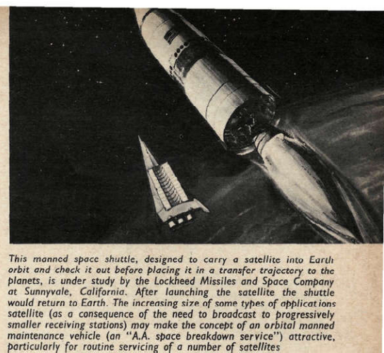
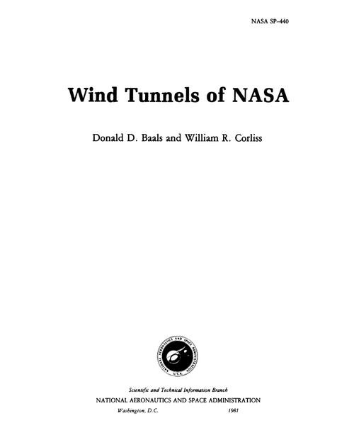
Artist's concept of the pre-Shuttle Lockheed sponsered Star Clipper stage-and-one-half lifting body configuration ascending from a desert launching base - circa 1968
Periodic publication for technical employees of the Lockheed Corporation including updates on research activities and data, ongoing programs, and related topics.
We already have two topics on Boeing TSTO designs, but this is neither the 1960s "Boomerang" nor the early 1980s Model 896. These photos by Angela Coyne appear in the National Archives and were taken on 18 October 1990. They are simply labeled "BOEING NASA TEAM AND TSTO MOD" and show four different models of various sizes. The T-tailed models are the carrier aircraft, while the smaller ones are the shuttles they are supposed to carry underneath.
Original photos (uncropped and unenhanced) can be found HERE.
This site uses cookies to help personalise content, tailor your experience and to keep you logged in if you register.
By continuing to use this site, you are consenting to our use of cookies.

")