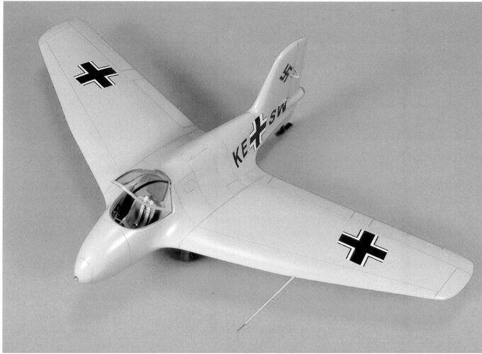
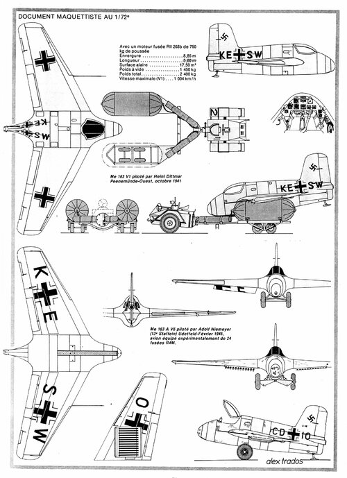
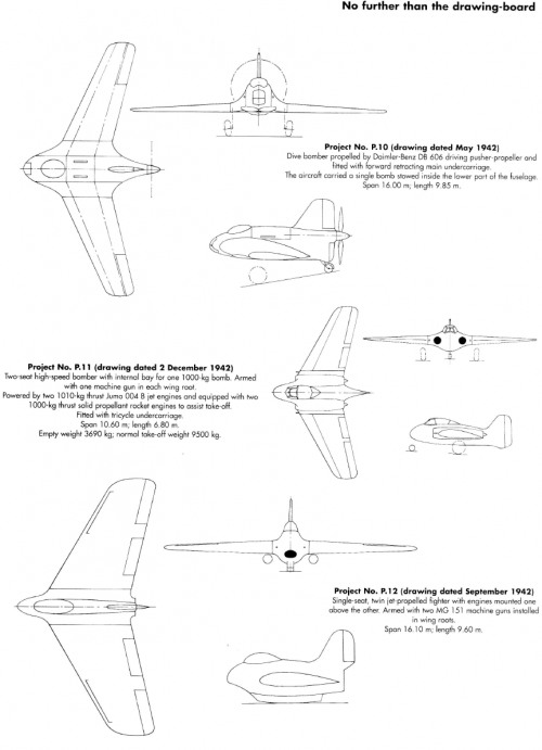
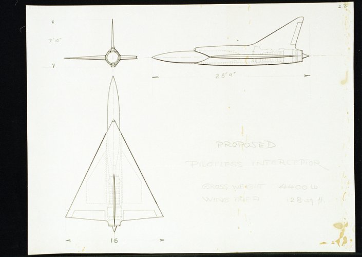
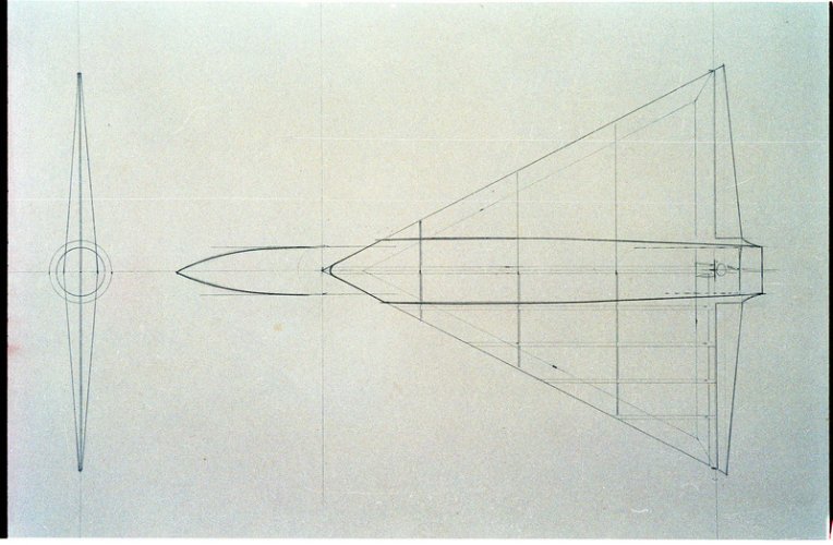
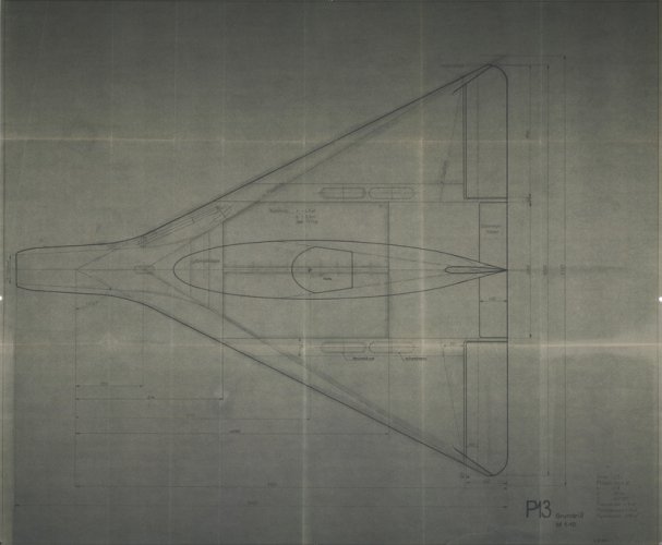
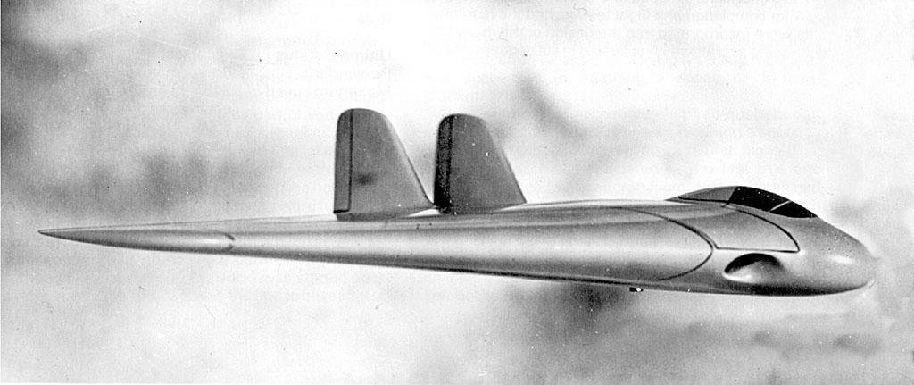
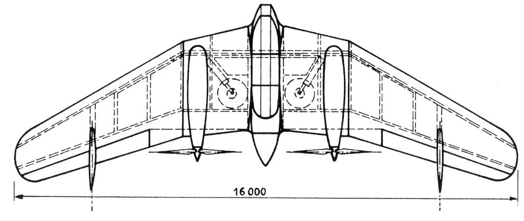
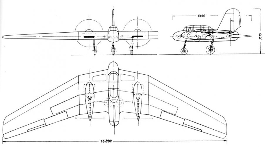
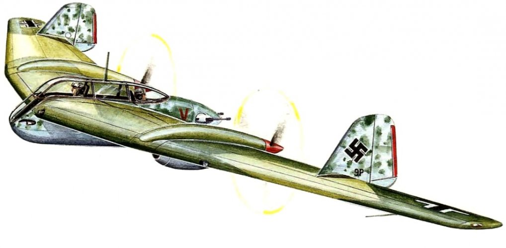
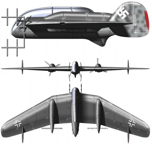
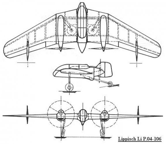
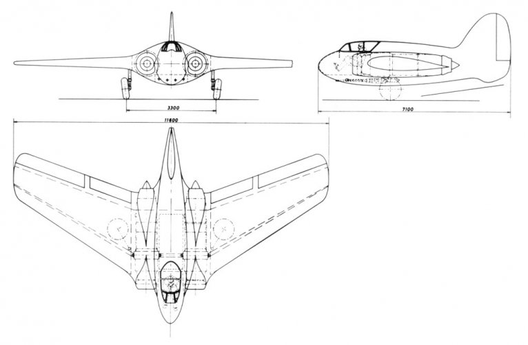
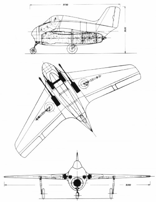
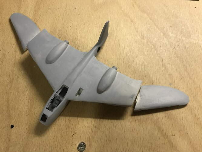
Hello, I am currently building a Lippisch P.10 on a scale of 1:72. Except for small parts, it is scratch-made. I scaled up the three-sided plan at Heinz J. Nowarra, Die deutsche Luftrüstung 1933-1945, Bernard & Graefe Verlag Koblenz.
Now my question: If the machine had been ready for series production, it would certainly not have been named P.10. Would it have been included in the Messerschmitt series, or would it have been named after Lippisch (similar to FW and Tank) and what number could it have recieved?

Many Thanks,

Greetings, ford.prefect

The issue of names for Lippisch's designs had been settled by this point. Lippisch wasn't allowed to call them, for example, Li 163. He did make a case for this but it was rejected and the decision was that his designs had to have the 'Me' prefix (at least, while he continued to work for Messerschmitt!).
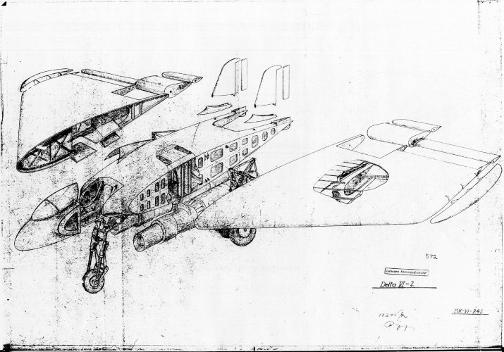
As you're no doubt aware, Lippisch pitched the P 10 (the version you are building) to Erhard Milch and received a contract to develop it. The RLM's engineers, however, were critical of the design and Lippisch decided to change it completely. The P 10 then became a tailless version of the Me 410 designed by Lippisch's assistant Walter Stender. Lippisch and Stender failed to inform the RLM about this change, however. Willy Messerschmitt, who did know about the change, went to the RLM to discuss the P 10 in September 1942 and was appalled to discover that 1) no-one knew anything about this new version and 2) because of the change, the development contract (which had applied to the original design) was now void.
The loss of this contract caused a great deal of animosity between Messerschmitt and Lippisch, and between Lippisch and Stender, with Lippisch seemingly blaming Stender for what had happened.
Ultimately, this seems to have hastened Lippisch's departure from the Messerschmitt company, with Stender going on to work for Zeppelin (I think).
Anyway, prior to all this acrimony, Messerschmitt (according to Lippisch) was going to apply 'Me 265' to the P 10 - the new version based on the Me 410. I guess that if the original P 10 hadn't been dropped, Me 265 might have been applied to that instead. I hope that answers your question.
 
Hello,

@newsdeskdan, thank you very much for the extensive information. However, I now have a problem with the designation "Me 265": I also build the machine named in this way. Here is a picture of the model under construction. It will be built as a carrier-supported aircraft, the separate wing parts will be shown folded.
I know that both aircraft would not have been realized in the real world. In fact, both have been replaced by the Me 329. I just find the designs fascinating and that's why I build them.
 

Attachments

  • Me 265 01.jpg
    Me 265 01.jpg
    526.1 KB · Views: 316
Last edited:
Hello,

@newsdeskdan, thank you very much for the extensive information. However, I now have a problem with the designation "Me 265": I also build the machine named in this way. Here is a picture of the model under construction. It will be built as a carrier-supported aircraft, the separate wing parts will be shown folded.
I know that both aircraft would not have been realized in the real world. In fact, both have been replaced by the Me 329. I just find the designs fascinating and that's why I build them.

Greetings, ford.prefect

The P 10 (designed by Lippisch) wasn't replaced by the Me 329 (designed by Hermann Wurster) - they were designed in parallel. In fact, the Me 329 has a slightly longer history, being derived from the P 04 line of development. A full report on the Me 329 - with the 'Me 329' designation already applied - was produced on March 15, 1942, whereas Lippisch's earliest known sketch for the P 10 dates from May 17, 1942.
At this time, Milch was pursuing a line of development he seems to have personally found very appealing - an unarmed bomber fast enough to avoid any attempt at interception by enemy fighters.
Wurster's Me 329 had two pusher props, each driven by a single engine (two engines, two props) - a configuration which in theory would make the aircraft faster than a machine with two tractor props. Lippisch's P 10 refined this concept even further by having just one pusher prop driven by a doubled engine (two engines, one prop).
It sort of made sense to pursue these two projects at the same time to see which would work out best. But when Lippisch's P 10 was scrapped and replaced by Stender's P 10/Me 265, there were now two designs which both had two engines and two pusher props. The advantage of Stender's P 10/Me 265 was its limited use of existing (Me 410) components.
What actually happened was, Messerschmitt decided to drop both of them and offer the RLM the Me 109 Zw instead (there is a consistent pattern of Willy Messerschmitt favouring designs from his Probue, rather than Abteilung L, which again contributed to Lippisch leaving the company). This was essentially two nacelles with no central fuselage - offering (in theory) an even better aerodynamic form, albeit with two tractor props, which had the advantage of using lots of existing components.
This eventually went head to head with Dornier's P 231 and lost at a crunch meeting on January 19, 1943. The P 231 (which refined the form even further to two engines and two props in a central fuselage with no nacelles) then became the Do 335.
 
Hello, thank you very much for the in-depth information. Unfortunately, this is not shown in the literature available to me. In relation to my models, this would mean that both are to be classified as Me 265 and may not be shown in the same universe. ;)
 
Hello, thank you very much for the in-depth information. Unfortunately, this is not shown in the literature available to me. In relation to my models, this would mean that both are to be classified as Me 265 and may not be shown in the same universe. ;)

I covered the P 10s and the Me 329 in Luftwaffe: Secret Wings of the Third Reich. My research on the Me 109 Zw and Dornier P 231 appears in Luftwaffe: Secret Designs of the Third Reich and I expand on the competition a little further in Luftwaffe: Secret Projects of the Third Reich. I really ought to compile the whole thing into a single book - the many designs which eventually led to the Do 335.
 
From, The Delta Wing History and Development,
 

Attachments

  • 3.png
    3.png
    98.3 KB · Views: 202
  • 4.png
    4.png
    148.9 KB · Views: 153
  • 5.png
    5.png
    102.4 KB · Views: 151
  • 6.png
    6.png
    134 KB · Views: 157
  • 7.png
    7.png
    162.5 KB · Views: 150
  • 8.png
    8.png
    121.9 KB · Views: 152
  • 9.png
    9.png
    136.7 KB · Views: 146
  • 10.png
    10.png
    132.9 KB · Views: 147
  • 11.png
    11.png
    136.3 KB · Views: 148
  • 12.png
    12.png
    57.6 KB · Views: 149
  • 13.png
    13.png
    95.7 KB · Views: 142
  • 14.png
    14.png
    56.6 KB · Views: 141
  • 15.png
    15.png
    86.8 KB · Views: 174
From, Ein Jahrhundert Flugzeuge Geschichte und Technik des Fliegens,

I think that was Lippisch design ?.
 

Attachments

  • 1.png
    1.png
    172.4 KB · Views: 158
From, The Delta Wing History and Development,
It's interesting that Lippisch used the P.01-116 designation for two different variants of a turbojet-powered airframe.

This is fully explained in my Luftwaffe: Secret Wings of the Third Reich. In essence, when he first started P 01, Lippisch drew up a list of different possible configurations numbered 111 to 119. He then picked 116 to work on first. The first drawings of this design are dated April 12 and April 13, 1939. Thereafter, Lippisch's team were frequently diverted by other work - particularly supporting Voigt's project office on conventional designs but also on the DFS 194.
The next P 01 was 111 and it didn't follow till November 1939. Then there was another gap till Feb 1940 when 112 followed, then another gap, then 113 and 114 in July 1940. A whole year later, in July 1941, Lippisch produced a pure-rocket 116 - skipping 115. Then he went back to the numerical sequence again for the 115, then a third 116 followed - the only one of the three 116s to actually appear in the numerical sequence. The long drawn-out timescale makes it easier, I think, to understand why multiple 116s weren't particularly confusing at the time.
 
Amazing article about Messerschmitt Me.263 in Flieger Revue Extra 102.
 
From this book.
 

Attachments

  • 12.png
    12.png
    1.8 MB · Views: 126
  • 11.png
    11.png
    3.4 MB · Views: 117
From, Lotnictwo 2005-7
 

Attachments

  • 18.png
    18.png
    3.3 MB · Views: 85
  • 19.png
    19.png
    3.4 MB · Views: 97
  • 20.png
    20.png
    3.6 MB · Views: 121
Hi,


Attachments

  • 1.jpg
    1.jpg
    142.9 KB · Views: 39
  • 3.jpg
    3.jpg
    84.3 KB · Views: 36
  • 4.jpg
    4.jpg
    195.6 KB · Views: 36
  • 6.jpg
    6.jpg
    85.8 KB · Views: 37
  • 8.jpg
    8.jpg
    77.7 KB · Views: 35
  • 9.jpg
    9.jpg
    99.7 KB · Views: 34
  • 10.jpg
    10.jpg
    56.8 KB · Views: 35
  • 11.jpg
    11.jpg
    104.5 KB · Views: 33
  • 12.jpg
    12.jpg
    82.8 KB · Views: 33
  • 13.jpg
    13.jpg
    57.6 KB · Views: 33
  • 14.jpg
    14.jpg
    95.1 KB · Views: 33
  • 15.jpg
    15.jpg
    131.8 KB · Views: 33
  • 16.jpg
    16.jpg
    165.7 KB · Views: 34
  • 28.jpg
    28.jpg
    71.5 KB · Views: 34
  • 27.jpg
    27.jpg
    206.3 KB · Views: 44
The narrator in that pops up here and there and has a gosh awful delivery. Makes my ears want to shut. Cannot get past that so left on the shelf, he is.
 

Attachments

  • 64462200_10156056431567260_6722349276871000064_n.jpg
    64462200_10156056431567260_6722349276871000064_n.jpg
    46.2 KB · Views: 20
  • 64572062_10156056435292260_946715275707809792_n.jpg
    64572062_10156056435292260_946715275707809792_n.jpg
    119.5 KB · Views: 17
  • 471515845_10160394252282260_2542335571417092018_n.jpg
    471515845_10160394252282260_2542335571417092018_n.jpg
    72.1 KB · Views: 13
  • Lippish P.11.jpg
    Lippish P.11.jpg
    75.5 KB · Views: 18
Last edited:
Lippisch P.11


UsageFlying wing jet fighter
StatusDesign
PowerplantTwo Junkers Jumo 004B turbojets 900 kg static thrust each
Span10.80 m
Wing Area50.0 m2
Aspect Ratio1.28
Length7.0 m
Range3,000 km
Maximum Speed1,200 km/h @ 5,900 m
Weight7,260 kg
ArmamentTwo MK 103 30 mm cannon

"After his time with the Darmstadt and Munich universities team Lippisch turned his attentions in 1944 to more warlike aircraft, whereupon he seems to have once more received the backing of the RLM.
Dating from 1944, the P.11 appears to have been designed in at least two forms. The first to come to light was a flying-wing fighter with a short nose, bubble canopy, end wing leading edges swept back at less than 45°. The trailing edges were straight, apart from a cutout in the center section, and the wingtips were cut off square. A pair of triangular fins were located on either side of the center-section cutout, and two Jumo 004 turbojets exhausted below and between them. An air intake was positioned in each wing leading edge on either side of the nose section. Fuel was to be carried in large tanks in each wing.(P.11-121)

Lippisch P. 11, fighter version
This version was to be developed in parallel with the Ho 229 flying-wing fighter, according to the minutes of a meeting of German aircraft development program planners on November 21 and 22, 1944. It was proposed that the Lippisch P.11 fighter would be further developed in collaboration with the Henschel aircraft company. A second version was similarly powered but was slightly larger, with a wing span of 41 ft (12.60m) and a length of 26 ft 6 in (8.07m). The cockpit canopy was removed from the upper surface and the pilot was located in the extreme nose behind a flush-fitting canopy. It was described as being designed for high speed bombing duties and based on the tailless Me 265 bomber project, with estimated maximum speed given as 560 mph at 32,800 ft (900 km/hr at 10,000 m)"
 

Attachments

  • September 1942 version of the P.11.jpg
    September 1942 version of the P.11.jpg
    100.6 KB · Views: 18
  • December 1942 version of the P 11.jpg
    December 1942 version of the P 11.jpg
    113.8 KB · Views: 18
  • lippisch_p-11-121_TURBOLET schematic.gif
    lippisch_p-11-121_TURBOLET schematic.gif
    102.9 KB · Views: 18
  • Version P11-121 was designed in May of 1943.gif
    Version P11-121 was designed in May of 1943.gif
    57.1 KB · Views: 17
  • The P.11-121 wind tunnel test model.jpg
    The P.11-121 wind tunnel test model.jpg
    51.9 KB · Views: 18
Last edited:

Attachments

  • lippisch_p_04-108_schematic.jpg
    lippisch_p_04-108_schematic.jpg
    74.6 KB · Views: 14
  • lippisch_p_04-114_schematic.jpg
    lippisch_p_04-114_schematic.jpg
    82 KB · Views: 13
  • lippisch_p_08_schematic.jpg
    lippisch_p_08_schematic.jpg
    94.1 KB · Views: 16
  • lippisch_supersonic_delta.jpg
    lippisch_supersonic_delta.jpg
    22.9 KB · Views: 17
  • dfs_40.gif
    dfs_40.gif
    21.2 KB · Views: 26
Last edited:

LIPPISCH-MESSERSCHMITT "P.04", FIGHTER


"Shortly after Alexander Lippisch began working at Messerschmitt AG (Division "L" – Lippisch), he submitted a design for a tailless night fighter-interceptor. Another distinctive feature of the design, along with the lack of a tail, was its telescopic landing gear, extending 1.9 meters when parked. The crew sat in a spacious, elongated cockpit, with the rear gunner controlling a pair of remote-controlled MK103 cannons, and a pair of MK151 cannons in the nose. The aircraft design was rejected by the RLM without explanation.

Crew – 2
Engines – 2 Daimler Benz 601E, 1200 hp
Length – 5.83 m
Width – 16.0 m
Height – 3.15 m
Max. Load – 2295 kg
Max. Speed – 510 km/h
Armament – 4×20-mm MK151 and 2×30-mm MK103"
 

Attachments

  • Lippish Messerschmitt p 04-106.jpg
    Lippish Messerschmitt p 04-106.jpg
    107.3 KB · Views: 14
  • 00100350-1.jpg
    00100350-1.jpg
    84.3 KB · Views: 17
  • p 04-106.jpg
    p 04-106.jpg
    283.8 KB · Views: 13
Last edited:

"In 1941, Prof. Rudolf Rentel was put in charge of the Lippisch P.09 project series. The first P.09 design dates from October 28, 1941 and followed the typical Lippisch tailless layout.
The fuselage was short and contained two unnamed turbojets (most probably Jumo 004s) in the wing roots. The wings were swept back at approximately 33 degrees. A large single fin and rudder was employe ed, with no horizontal tail planes since this was a tailless design. The two main landing gear were attached just outboard of the engines, and retracted to the rear and stowed into the wing. A tail bumper was used instead of a rear wheel. The cockpit was located near the fuselage front, overlooking the aircraft's nose. Armament was projected to be four machine guns or cannon all firing below the cockpit.
This project did not progress past the early design stages, it was only one of many of Lippisch's tailless aircraft designs."
 

Attachments

  • lippisch_p_09_turbojet_schematic.jpg
    lippisch_p_09_turbojet_schematic.jpg
    68.6 KB · Views: 12
  • lippisch_p_09_rocket_schematic.jpg
    lippisch_p_09_rocket_schematic.jpg
    88.6 KB · Views: 13
"Lippisch P.010was the designation for two different designs by Alexander Lippisch , head of "Department L" at the Messerschmitt works . The first design, from November 1941, envisioned a destroyer with two jet engines, while a second design from May 1942 dealt with the construction of a propeller-driven fast bomber. Both concepts used the basic layout typical of the Me 163 as a tailless mid-wing monoplane, but with significantly larger dimensions." (Wikipedia)
 

Attachments

  • lippisch_p_10_turbojet_schematic.jpg
    lippisch_p_10_turbojet_schematic.jpg
    165.5 KB · Views: 14
  • lippisch_p_10_propeller_schematic.jpg
    lippisch_p_10_propeller_schematic.jpg
    72.6 KB · Views: 14
Last edited:
"The Lippisch P.15was a proposed World War II German fighter aircraft.

Development​

Alexander Lippisch designed the Li P.15 after inspecting the new Heinkel He 162 which he thought could be improved. The redesigned He 162 composed of the nose section of the Heinkel 162, the wings and tail of the Me 163C, a newly designed rear fuselage, and landing gear adapted from the Bf 109.

Power was to be supplied by a single Heinkel HeS 011 A turbojet contained within the rear fuselage, which was fed by two intakes buried in the wing roots.

Though the full-scale plane was never actually built, modelers can purchase a Radio Control model version.

Specifications​

General characteristics
  • Crew: 1
  • Length: 6.4 m (21 ft 0 in)
  • Wingspan: 10.08 m (33 ft 1 in)
  • Powerplant: 1 × Heinkel HeS 011 turbojet engine, 12.7 kN (2,900 lbf) thrust
Performance
  • Maximum speed: 1,000 km/h (620 mph, 540 kn)
Armament
  • Guns: 2x 20 mm MG 151/20 autocannon in the wing and 2x 30 mm MK 108 cannon in the forward fuselage sides"
(Wikipedia)
 

Attachments

  • lippisch_p-15_schematic.gif
    lippisch_p-15_schematic.gif
    54.1 KB · Views: 20
  • Lippisch_P.15_sketches.jpg
    Lippisch_P.15_sketches.jpg
    126.6 KB · Views: 20
  • images.jpg
    images.jpg
    298.1 KB · Views: 22
Last edited:
"The Lippisch P.20 was a proposed World War II German fighter aircraft. The P.20 design of April 1943 was an attempt to further develop the rocket-powered Me 163 interceptor into a turbojet-powered fighter. The design was the final one by Alexander Lippisch whilst working for the Messerschmitt company.

Design and development​

The aircraft was externally similar to the Me 163 upon which it was based, although the P.20 was in fact a new design sharing only a few parts with the Me 163. The fuselage was deepened accommodating a single Jumo 004 turbojet fed by a low mounted nose intake. The wings were modified in order to house the retractable landing gear and two heavy MK 103 autocannons in the wing roots. The C-Stoff fuel tanks would have replaced by ones for jet fuel. The cockpit was moved further aft and upwards leaving room for two MK 108 autocannons and the nose wheel. This had to turn 90 degrees to lie flat in order not to disrupt the air flow of the air intake.

As such the Lippisch P.20 was a new design, yet holding on to the overall concept of the Me 163 design which had resulted in a manoeuvrable and easy-to-fly (glider) aircraft. Maximum speed was calculated at well above 900 kmh with a flight endurance of 40 minutes."(Wikipedia)
 

Attachments

  • lippisch_p-20_turbojet_schematic.jpg
    lippisch_p-20_turbojet_schematic.jpg
    326.1 KB · Views: 23
Last edited:

Similar threads

Back
Top Bottom