McDonnell-Douglas Model 279 VSTOL fighter

Deino

Moderator
Staff member
Top Contributor
Senior Member
Joined
2 January 2006
Messages
3,517
Reaction score
3,072
Model 279

[pictures replaced with higher resolution copy below]
 

Attachments

  • McDonnell Douglas model 279 - 03 2 side plan.jpg
    McDonnell Douglas model 279 - 03 2 side plan.jpg
    406.3 KB · Views: 1,885
  • McDonnell Douglas model 279 - 04 3 side plan.jpg
    McDonnell Douglas model 279 - 04 3 side plan.jpg
    251.9 KB · Views: 1,612
Deino your collection is incredible!!. Thank you very much for your posts, I'm learning a lot!

Here's something from mine

One more on McDonnell Douglas model 279-3
 

Attachments

  • McDD Model 273-3.jpg
    McDD Model 273-3.jpg
    80.4 KB · Views: 1,211
A more powerful 279 variant, the 279-4. Source is an Spanish translation from a Salamander Guide from 1986. Spanish tittle: "Guía Ilustrada de Cazas del Siglo XXI".
The 279-4 has two afterburner Pegasus engines, side by side.
 

Attachments

  • McDD Model 279-4.jpg
    McDD Model 279-4.jpg
    108.7 KB · Views: 1,065
McDonnell-Douglas Model 279


[Removed some images - better copies below - Admin]
 

Attachments

  • 1987_09305L.JPG
    1987_09305L.JPG
    22.3 KB · Views: 857
More stuff from NASA technical reports
 

Attachments

  • 279-3b.jpg
    279-3b.jpg
    45.7 KB · Views: 333
  • 279-3.jpg
    279-3.jpg
    82.2 KB · Views: 347
Here is an article from the fantastic Flight archives http://www.flightglobal.com/PDFArchive/View/1984/1984%20-%200705.html?search=STOVL
 
Thanks Steve - downloaded that page months ago but never posted it...

These pictures depict the McDonnell Douglas Model 279-3 concept for a Stovl fighter. A 9.2 per cent scale model f top,) is about to begin windtunnel testing at Nasa's Ames facility. The proposed aircraft ( centre) uses 41 per cent composites and is powered by an advanced Rolls-Royce Pegasus in four-poster configuration producing 36,900lb thrust with fan stream burning. Maximum speed is Mach 2.0 with acceleration from Mach 0.8 to Mach 1.6 in 70sec. Model 279-3 is one of four Stovl concepts now being evaluated for further work by Nasa
 

Attachments

  • 279-3c.jpg
    279-3c.jpg
    82.8 KB · Views: 433
  • 279-3d.jpg
    279-3d.jpg
    55.3 KB · Views: 380
http://www.flightglobal.com/PDFArchive/View/1982/1982%20-%200437.html

Powered by a Pratt & Whitney STF561-C2 turbofan producing 34,000lb with plenum chamber burning, the McDonnell Douglas
Model 279-3 can reach Mach 2. VTO weight is 29,840lb for a 103 n.m. combat radius

Not surprisingly, the McDonnell Douglas submission is a vectored thrust design based on the proven Harrier/Pegasus principle a single 1: 1 bypass-ratio turbofan fitted with rotating nozzles which divert fan and core air downwards for take-off and landing, rearwards for forward flight, and anywhere in between for STO or manoeuvring.Add reheat to the forward, "cold" nozzles and the concept is suitable for supersonic aircraft. Plenum chamber burning (PCB) brings with it design problems, but they can be identified more clearly at this stage than those of any other approach. The engine, with its large-diameter fan, must be located close to the e.g., resulting in an unfashionably fat fuselage. This must be stretched, adding weight, to achieve reasonably low supersonic drag. So much fiery air expelled close to the ground can pose both exhaust reingestion and ground-erosion problems.

The McDonnell Douglas Model 279-3 is a wing/canard design with a 48,800lb gross weight for a ski-jump take-off. Powerplant is a PCB-equipped Pegasus-type engine by Pratt & Whitney, associate to Rolls-Royce on the US Marine Corps AV-8B Harrier II programme. Instead of the raked intakes associated with supersonic flight, the Model 279-3 has short inlets of the type used successfully on the AV-8B, but with half-cone centrebodies.

The all-moving canard destabilises the aircraft, so a digital fly-by-wire flight-control system is used to restore stability artificially. Relative position and output of the front and rear nozzles is governed by the flight-control system for pitch control and vectoring in forward flight: Vtol pitch attitude is controlled by modulating thrust from the forward nozzles, while differential deflection of front and rear nozzles helps lift the nose when wing high-lift flaps are lowered.
 

Attachments

  • 279-3e.jpg
    279-3e.jpg
    85.8 KB · Views: 339
http://www.flightglobal.com/PDFArchive/View/1984/1984%20-%200676.html

McDonnell Douglas pursues Harrier concept

McDonnell Douglas is fully committed to the four-poster vectored thrust concept for its supersonic Stovl fighter design. Windtunnel testing of a 9.2 per cent scale model at Nasa's Ames facility is imminent, and will last 1,500hr. The Model 279-3 is designed to Navy requirements issued 2 years ago. The aircraft uses 41 per cent composites by weight, and draws on technology developed for the AV-8B, F-15, and F-18, all of which are now in production at St Louis. Model 279-3 is a Mach 2.0 aircraft, capable of pulling 6-9g at Mach 0-65 and accelerating from Mach 0.8 to Mach 1.6 in 70sec at 35,000ft. "It has F-15 manoeuvre characteristics combined with vertical take-off and landing," says Dick Martens, senior advanced V/Stol programme engineer at McDonnell Douglas.

Low risk is the theme of MD's work. The company is throwing a lot of effort into developing an idea it is confident could work. Its plenum-chamber burning design aims to equalise all four nozzle temperatures, possibly using independent vectoring front and rear. Integration of engine and airframe would draw on ideas now being developed by the company for its Advanced Tactical Fighter design, due to be submitted to the USAF soon. Windtunnel testing will concentrate on solving hot gas re-ingestion (HGR) and ground effects problems. Like Rolls-Royce, it suggests sizing the engine upwards to reduce PCB temperatures. Dick Martens notes that in any case the need for good acceleration to supersonic speed dictates a larger engine than currently used. Another point, he says, is that a surprisingly small reduction of thrust in such an engine results in a useful drop in PCB temperatures. Hot gas-re-ingestion trials are being Pegasus on full PCB at Shoeburyness. PCB would boost the thrust of today's Pegasus II to more than 30,000lb carried out using water and a 4.1 per cent scale model. Dyed water will be pumped through oversized front nozzles and illuminated by laser so that effects of toeing in the nozzles, auxiliary engine inlets and retractable deflectors can be assessed. Extra MD funding covers research into ground and suckdown effects, looking in particular at the use of lift improvement devices (Lids). "It's all inexpensive testing," says Martens.

A demonstrator, if funded, would also be a low-cost machine, with forward cockpit and fin from the F/A-18, canard from the A-7 (tail), and an AV-8A wing. Co-ordination of the work being done by McDonnell Douglas and other US manufacturers with that under way in the UK is the aim of a Memorandum of Understanding that should be signed before long by the two Governments. The idea is to formalise the supersonic Stovl effort, rationalise the many concepts being proposed, and concentrate resources. In the USA the job of co-ordination is more difficult than in the UK, where research means the Royal Aircraft Establishment, and the industry is British Aerospace and Rolls-Royce. Nasa has already received proposals from the many interested airframe and engine companies and is working now to identify critical technologies thought suitable for further study. The hope is that the USA and UK will be able to exchange technology plans before the Farnborough Air Show, so that final discussions on a joint technical plan for each of the four main concepts can be completed around show time. The four concepts are: PCB Harrier (McDonnell Douglas); ejector (General Dynamics); remote augmented lift system (Grumman); and tandem fan (Vought). A detailed description of each concept appeared in our last Military Propulsion special, published on January 15, 1983.
 
4.2.2.2 McDonnell-Douglas
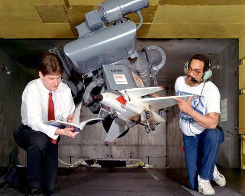
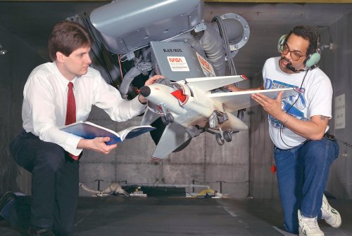
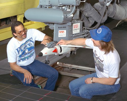
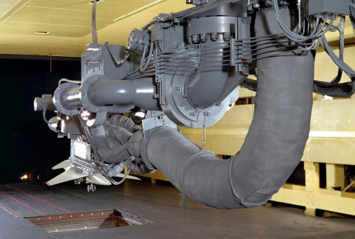
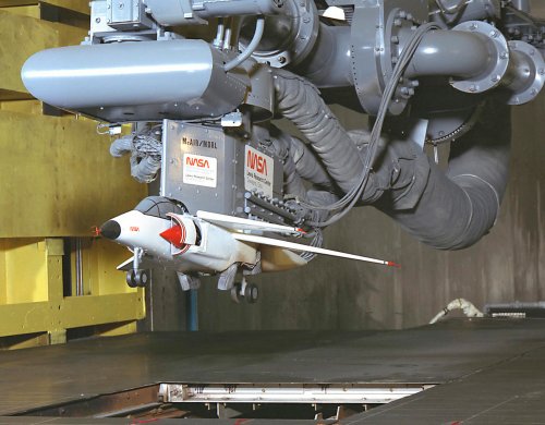
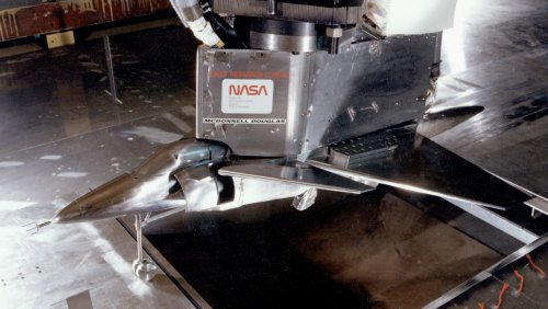
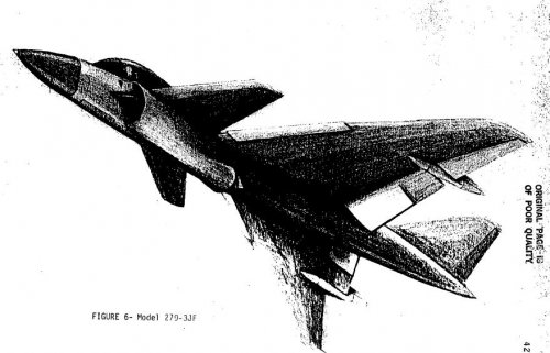
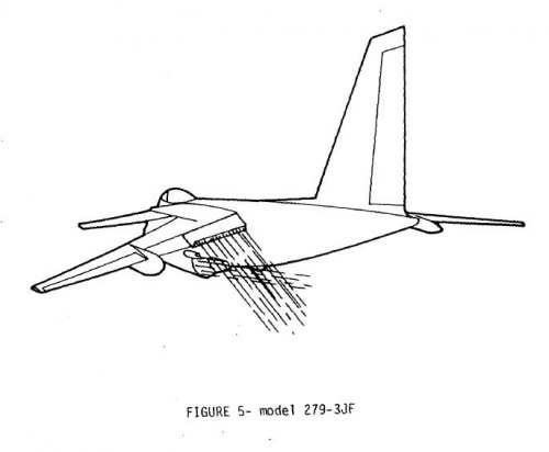
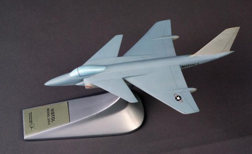
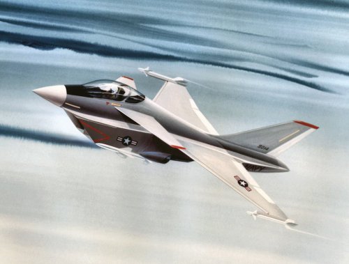
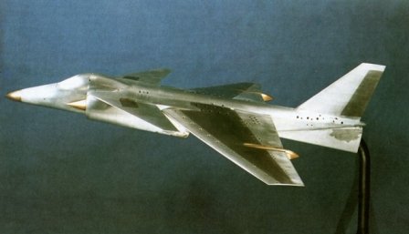
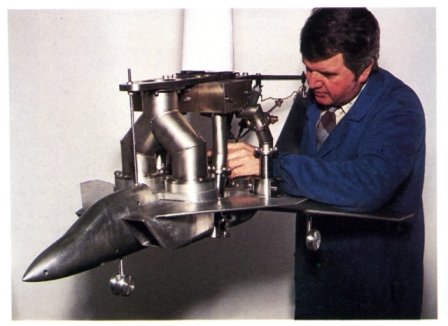
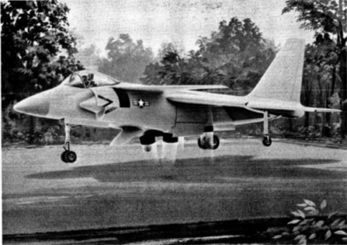
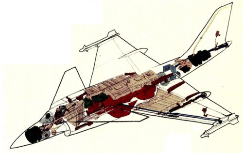
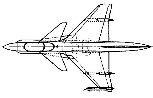
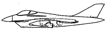
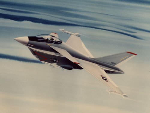
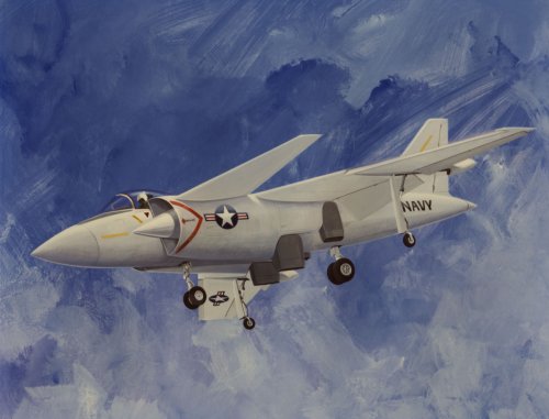
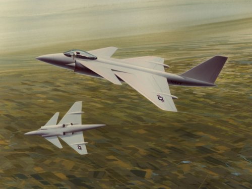
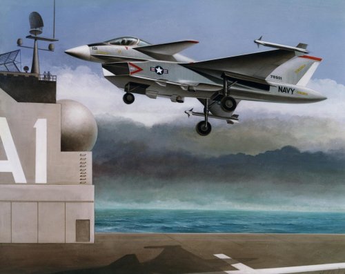
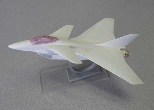
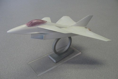
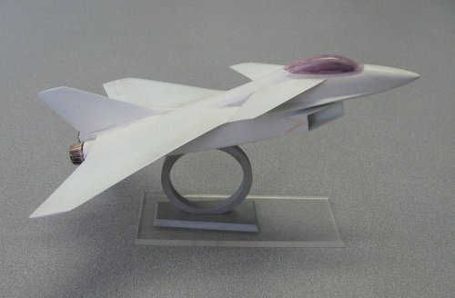
The concepts studied by McDonnell-Douglas (MCAIR) is a canard/wing design with swiveling nozzles forward and aft of the aircraft center of gravity. The four poster configuration, MCAIR model 279-3, is seen in Figs. 69 and 70; 69 depicts the vertical flight configuration, and the cruise flight mode is shown in Fig. 70. References 51 and 58 give details of this concept.

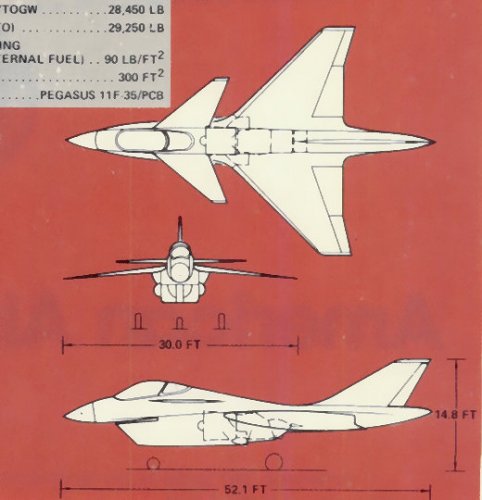
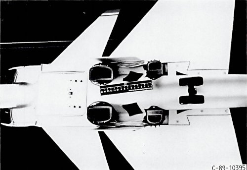
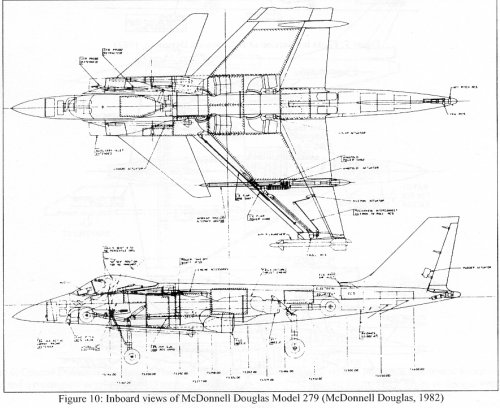
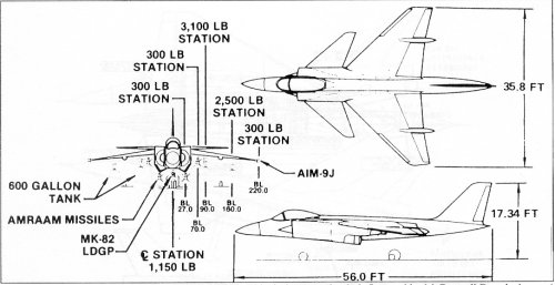
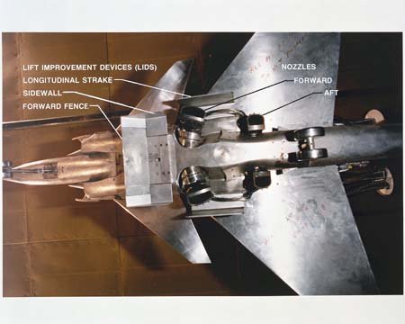
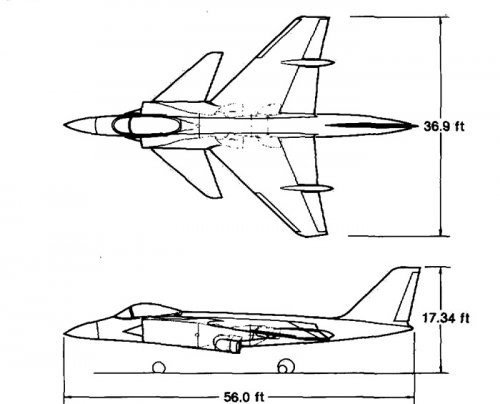
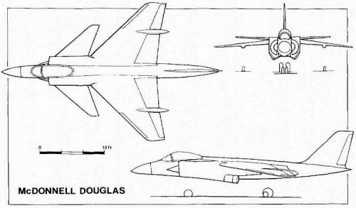
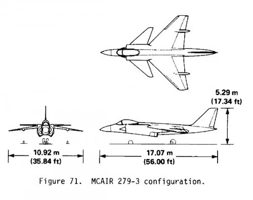
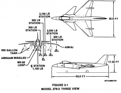
Configuration. Model 279-3 features a close-coupled canard and side-mounted half-axisymmetric inlets to provide air to a single engine with modulated fan-stream augmentation. Four swiveling nozzles provide thrust vectoring capability for vertical flight as well as for in-flight maneuvering. Fan air flows through the forward nozzles and the engine core flow exits through the aft nozzles. Modulation of the fan stream and engine speed provides the capability of trimming center of gravity travel associated with fuel burnoff and store loading. This modulation can also provide a portion of the pitch maneuvering control or can be used as a backup system. The location of the aft nozzles near the wing trailing edge offers the potential of enhanced circulation, translating into increased maneuverability and STOL performance. Thrust vectoring can increase the sustained load factor of Model 279-3 by 0.2 g and the instantaneous load factor by 2.0 g's at 0.6 Mach number at an altitude of 3,048 m (10,000 ft). As shown in Fig. 69, the main landing gear of Model 279-3 are located fore and aft on the fuselage in a bicycle fashion with outriggers in pods on the wing. Three views of the MCAIR concept are shown in Fig. 71, and a dimensional summary is given in Table 9. The wing has an aspect ratio of 3.0, a leading-edge sweep of 45 ° , and 9° of anhedral. The close-coupled canard is mounted high on the inlet sides and has 0 ° of dihedral, a leading-edge sweep of 50 °, and an aspect ratio of 3.0. The exposed area of the canard is 20% of the wing reference area. The single vertical tail is mounted on the aft fuselage.The configuration has a vertical takeoff wing loading of 3.34 kN/m 2 (69.7 Ib/ft 2) and a tropical-day, vertical-takeoff, thrust-to-weight ratio of 1.15 with full fan-stream burning.

Aerodynamic Surfaces. Pitch control is provided by the all-movable, close-coupled horizontal canard; roll control by the differential ailerons; and directional control by the rudder. The wing leading and trailing edge flaps and also the canard are deflected as a function of angle of attack and Mach number to maximize maneuvering capability. The leading edge flaps also are used supersonically as decamber flaps to reduce drag. The trailing edge flaps, which are plain flaps at small deflections, become single slotted flaps at large deflections, for high-lift operation. These flaps, which are close to the aft nozzle, increase the STOL lift. The location of the forward nozzle under the wing, rather than at the leading edge, also improves lift during STOL.The wing planform selection is based on a compromise between subsonic and supersonic performance. Subsonic emphasis is on high sustained maneuverability requiring low drag due to lift. Supersonic emphasis is on lower-lift-coefficient maneuvering conditions during which the minimum drag coefficient CDo is equally important.The wing airfoil camber increases outboard on the wing. There is no twist at the wing-fuselage juncture, but there is leading-edge-down twist at the wing tip.

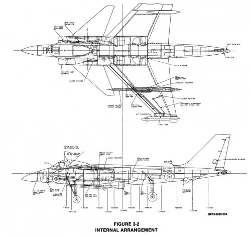
Control System. The Model 279-3 has a digital fly-by-wire control system, which is necessary to augment the subsonic longitudinal instability. This active control system also makes possible (1) engine/fan-stream augmentation/reaction-control-system integration, (2) augmented thrust-vectoring control, and (3) coupled flight/propulsion control. A three-axis reaction control system (RCS), operating on engine bleed air, provides control moments independent of dynamic pressure. During VTOL operation it provides the complete maneuvering control. The pitch RCS is located in the aft fuselage and the forward lower mold line of the inlet, just forward of the nose gear. The lateral RCS thrusts both up and down in opposite wing tips. The directional RCS, thrusting laterally in either direction, is located in the aft tip of the fuselage. During VTOL operation the thrust center is positioned by varying the engine speed and the fan-stream augmentation, using the flight controller. Decreasing the forward nozzle thrust moves the thrust center aft, with the level of thrust maintained by increasing the engine speed. This provides the static trim during VTOL; transient control is provided by the pitch RCS. Additional control is provided by the engine nozzle thrust-vectoring control (TVC). The fore and aft nozzles are symmetrically deflected a small amount for rapid load-factor changes, with rapid turns plus deceleration followed by acceleration. Differential deflection of the fore and aft nozzles is used for STOL control to augment the canard deflection in controlling the high-lift flap pitching moment.

Propulsion System. A single, advanced Pratt and Whitney thrust-vectoring engine (STF 561-C2) with fanstream augmentation serves as the propulsion system. It has a twin-spool turbofan gas generator utilizing a two-stage fan and a five-stage low-aspect-ratio high-through-flow axial compressor with a single-stage, high pressure turbine and a two-stage, low-pressure turbine. The bypass ratio is 1.16, the overall pressure ratio is 25.0, and the fan pressure ratio is 3.50. Table 10 gives additional propulsion system characteristics.The forward, side-mounted nozzles incorporate fan-stream burning augmentors. There is no engine-core augmentation associated with the aft nozzles. The half-axisymmetric, side-mounted inlets have fixed 16.5° half-conical spikes.

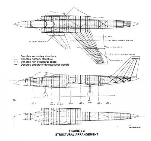
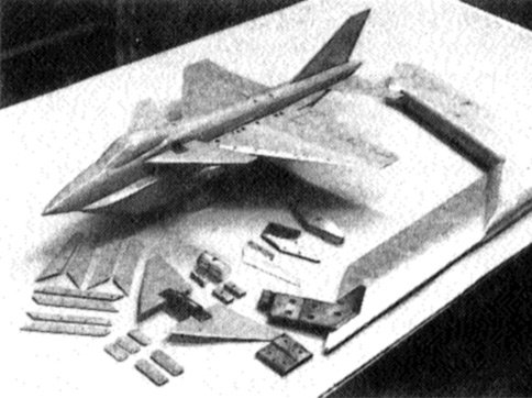
Structure. Composites are used extensively in the Model 279-3. The structural weight consists of 41% graphite epoxy, 21% aluminum, 13% titanium, 8% steel, and 17% other materials. Graphite epoxy is distributed as follows: wing 50%, canard 52%, vertical tail 65%, fuselage 46%, and the engine section 55%.

Mission Performance. MCAIR sized the configuration to the vertical-takeoff, supersonic, DLI mission defined in Fig. 72. Weapons and ammunition are retained throughout the mission. To accomplish this mission and remain within the guideline vertical takeoff gross weight of 13,606 kg (30,000 Ib), the aircraft has a mission radius of 191 km (103 nmi.) and a vertical takeoff gross weight of 13,535 kg (29,840 lb). With full internal fuel [gross weight = 14,161 kg (31,220 lb)] and a rolling takeoff of less than 15 m (50 ft), the radius of the DLI mission is increased to 296 km (160 n. mi.) A weight summary for the vertical takeoff supersonic DLI mission is given in Table 11.

Performance of the Model 279-3 and NASA guideline performance are shown in Table 12. As indicated, all performance requirements are met or exceeded.

The STO characteristics of the Model 279-3 with full internal fuel have been determined by MCAIR for both a flat deck and a 12 ° ski jump. For a 122-m (400-ft) flat-deck run'with zero wind over the deck, the Model 279-3 has an STO gross weight of 18,960 kg (41,800 Ib) as shown in Table 12. With this same takeoff run, the STO weight is increased 17%, to 22,135 kg (48,800 Ib) using the ski jump.

http://ntrs.nasa.gov/archive/nasa/casi.ntrs.nasa.gov/19840014464_1984014464.pdf
 

Attachments

  • 279-3nasa.jpg
    279-3nasa.jpg
    40.7 KB · Views: 251
According to Bill Sweetman, this is one of Model 279 iterations in NASA Ames wind tunnel.
Hi-res version here http://grin.hq.nasa.gov/IMAGES/LARGE/GPN-2000-001637.jpg
 

Attachments

  • GPN-2000-001637.jpg
    GPN-2000-001637.jpg
    275.4 KB · Views: 164
Pictures from McDD NASA contractors report

http://ntrs.nasa.gov/archive/nasa/casi.ntrs.nasa.gov/19840020698_1984020698.pdf
 

Attachments

  • 279-3a.jpg
    279-3a.jpg
    199.4 KB · Views: 294
  • 279-3b.jpg
    279-3b.jpg
    170.6 KB · Views: 345
  • 279-3c.jpg
    279-3c.jpg
    130.1 KB · Views: 300
279-1, early configuration. Source as above.
 

Attachments

  • 279-1c.jpg
    279-1c.jpg
    30.7 KB · Views: 206
  • 279-1b.jpg
    279-1b.jpg
    15.6 KB · Views: 215
  • 279-1.jpg
    279-1.jpg
    54.3 KB · Views: 185
Flateric's model identified as 279-3 forces and moment wind tunnel model. As above.
 

Attachments

  • 279-3e.jpg
    279-3e.jpg
    84.4 KB · Views: 284
From an evolutionary point of view, it's a PCB "Super Harrier" with the tail moved to the front.
 
Greetings All -

Model 279 related artwork I found in the Greater St. Louis Air & Space Museum archives. Some are repeats of previous art but higher resolution.

Enjoy the Day! Mark
 

Attachments

  • xD4C-120187-1 Feb-83.jpg
    xD4C-120187-1 Feb-83.jpg
    162.9 KB · Views: 997
  • xD4C-119690-2 Jul-81.jpg
    xD4C-119690-2 Jul-81.jpg
    177.5 KB · Views: 1,076
  • xD4C-1197787-2 Dec-81.jpg
    xD4C-1197787-2 Dec-81.jpg
    176.3 KB · Views: 1,131
  • xD4C-118809-2 Oct-79.jpg
    xD4C-118809-2 Oct-79.jpg
    135.7 KB · Views: 1,154
Really beautiful artwork Mark. The first one with the ventral intake is the early configuration posted on the previous page.
 
Greetings All -

A couple of new finds to add the thread....

Enjoy the Day! Mark
 

Attachments

  • McDonnell Douglas 279 no stores artwork.jpg
    McDonnell Douglas 279 no stores artwork.jpg
    199.6 KB · Views: 857
  • McDonnell Douglas 279 with stores artwork.jpg
    McDonnell Douglas 279 with stores artwork.jpg
    187.8 KB · Views: 338
Good Day All -

I recently picked up the aviation collection of a friend who passed away earlier this year. Most of the collection is made up of 35mm slides but in the prints I came across the following artwork. When I saw this, I realized it matched many of the features of a small McDonnell Douglas model we have in the Museum collection. Any ideas on a Model #?

Enjoy the Day! Mark
 

Attachments

  • xMG_1677.jpg
    xMG_1677.jpg
    87.9 KB · Views: 228
  • xMG_1676.jpg
    xMG_1676.jpg
    79.9 KB · Views: 211
  • xMG_1673.jpg
    xMG_1673.jpg
    82.4 KB · Views: 222
  • xMG_1672.jpg
    xMG_1672.jpg
    88.2 KB · Views: 458
  • xMcDonnell Douglas canard STOL fighter concept.jpg
    xMcDonnell Douglas canard STOL fighter concept.jpg
    109.5 KB · Views: 578
Mark,

that McDonnell Douglas concept has a similar intake arrangement used on McDD's ATF proposal.

see:
http://www.secretprojects.co.uk/forum/index.php/topic,399.0/all.html
reply#22
 
Mark Nankivil said:
Good Day All -

I recently picked up the aviation collection of a friend who passed away earlier this year. Most of the collection is made up of 35mm slides but in the prints I came across the following artwork. When I saw this, I realized it matched many of the features of a small McDonnell Douglas model we have in the Museum collection. Any ideas on a Model #?

Enjoy the Day! Mark


Mark,

Sorry to hear about your friend.

I believe these are variants of the Model 279-1, which led to the 279-3 with side inlets, which was more widely publicised. More here: http://www.secretprojects.co.uk/forum/index.php/topic,2655.msg34518.html#msg34518

Different intake and rear nozzle (single, not bifurcated) in the artists's impression, so maybe this is the -2. The model appears to be a (twin engined) STOL/CTOL derivative.

Very nice image and model pics - thanks for sharing.

Mike
 
Thanks All - I'm embarrassed to say I missed the connection to the other artwork I posted previously. :-[

Enjoy the Day! Mark
 
Is it a safe bet to consider the attached artwork as somehow related to the Model 279-1 configuration, despite the different intakes and exhausts?


index.php
 
Is it a safe bet to consider the attached artwork as somehow related to the Model 279-1 configuration, despite the different intakes and exhausts?

I have my doubts too.
 
Large copies of these images, NASA via Archive.org. Minor cropping to reduce filesizes and focus on the model.
 

Attachments

  • 1990_04389a.jpg
    1990_04389a.jpg
    700.5 KB · Views: 176
  • 1990_04390a.jpg
    1990_04390a.jpg
    601.3 KB · Views: 135
  • 1990_04378a.jpg
    1990_04378a.jpg
    431.8 KB · Views: 116
  • 1990_04071a.jpg
    1990_04071a.jpg
    665.1 KB · Views: 108
  • 1990_04384a.jpg
    1990_04384a.jpg
    249 KB · Views: 120
  • 1987_04914a.jpg
    1987_04914a.jpg
    593.3 KB · Views: 151
Nice pics, Paul, and I love the Paris-Le Bourget Airshow T-shirt in the pictures!!
 
Posted in the Advanced Harriers topic, this is clearly some form of early Model 279. engine has non-bifurcated rear exhaust.
 

Attachments

  • MDD supersonic stovl (1).jpg
    MDD supersonic stovl (1).jpg
    50.2 KB · Views: 1,051
Nice shot of the 279-3 model underside.


Source: Hot Gas Ingestion Test Results of a Two Poster Vectored Thrust Concept With Flow Visualization in the NASA Lewis 9- by I5-Foot Low Speed Wind Tunnel
Albert L. Johns, George Neiner, and Timothy J. Bencic, Lewis Research Center, Cleveland, Ohio and Joseph D. Flood, Kurt C. Amuedo, and Thomas W. Strock, McDonnell Douglas Corporation, St. Louis, Missouri

http://ntrs.nasa.gov/archive/nasa/casi.ntrs.nasa.gov/19910011803_1991011803.pdf
 

Attachments

  • 279-3 Model Underside.jpg
    279-3 Model Underside.jpg
    78.5 KB · Views: 984
Here is an info about Model 279-3JF;

To investigate the benefit in increased payload, the 279-3 and
the jet flapped 279-3JF were modeled on NASA's "Aircraft Synthesis
(ACSYNT) computer code and flown on a 250 ft. takeoff distance interdiction
mission. The increase in payload weight that the 279-3JF could
carry was converted into fuel in one case, and in another, converted
to bomb load. When the fuel was increased, the 279-3JF penetrated into
enemy territory almost four times the distance of the 279-3, and therefore
increased mission capability. When the bomb load was increased,
the 279-3JF carried 14 bombs the same distance the 279-3 carried four.
This increase in mission performance and improvements in turning rates
was realized with only a small penalty in increased empty weight.


http://ntrs.nasa.gov/archive/nasa/casi.ntrs.nasa.gov/19860021250_1986021250.pdf
 

Attachments

  • 279-3JF   1.JPG
    279-3JF 1.JPG
    26.6 KB · Views: 799
  • 279-3JF   2.JPG
    279-3JF 2.JPG
    81 KB · Views: 784
Manufacturer desk model of the McDonnell Douglas 279-3 V/STOL fighter.
 

Attachments

  • MDC 279-3 01.jpg
    MDC 279-3 01.jpg
    76.3 KB · Views: 618
Model 279-1 picture posted on Facebook by Ian Allan Publishing.
 

Attachments

  • 1146824_432704476843943_660297140_o.jpg
    1146824_432704476843943_660297140_o.jpg
    138.9 KB · Views: 216
Hi, Everyone
Hope things are going well. I've been reading this post and need help. I have a drawing of the 279-4 that has D shaped intakes,but all the pics and artist renderings have F-15 style intakes. Does anyone have a 3 view of the version with F-15 style intakes?
Thanks
 

Similar threads

Back
Top Bottom