FighterJock
ACCESS: Above Top Secret
- Joined
- 29 October 2007
- Messages
- 7,253
- Reaction score
- 8,567
Don't think so somehow quellish about Android, far more likely to be a take of from Linux instead.

What do you think Android is?Don't think so somehow quellish about Android, far more likely to be a take of from Linux instead.

Don't think so somehow quellish about Android, far more likely to be a take of from Linux instead.
Android, and the pilot has to watch 3 ads before he can send a command to a CCA.
 .
.

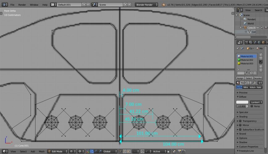
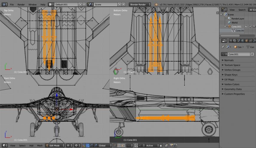
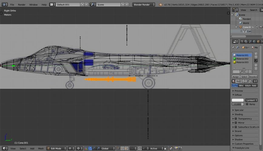
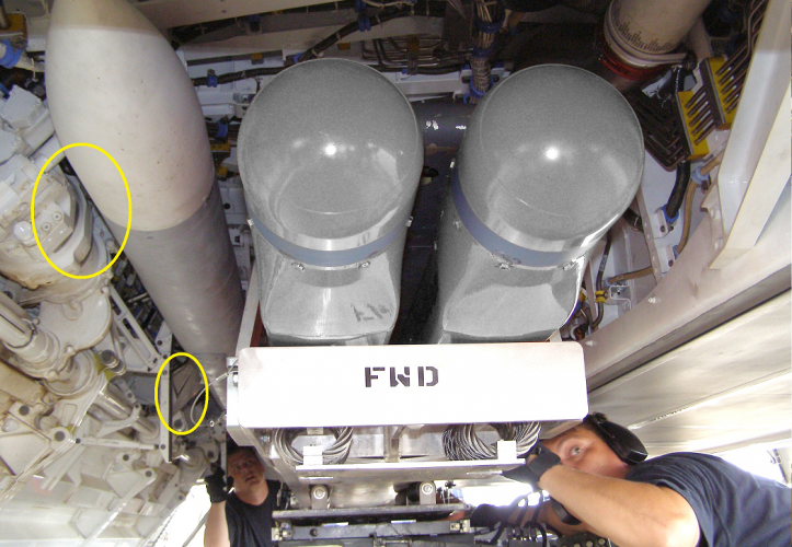
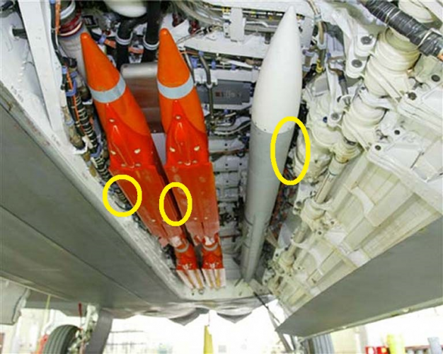
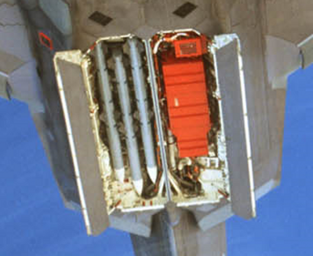
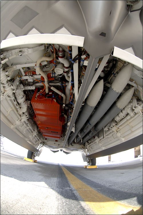
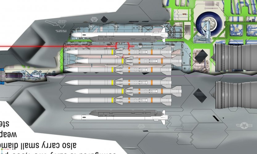
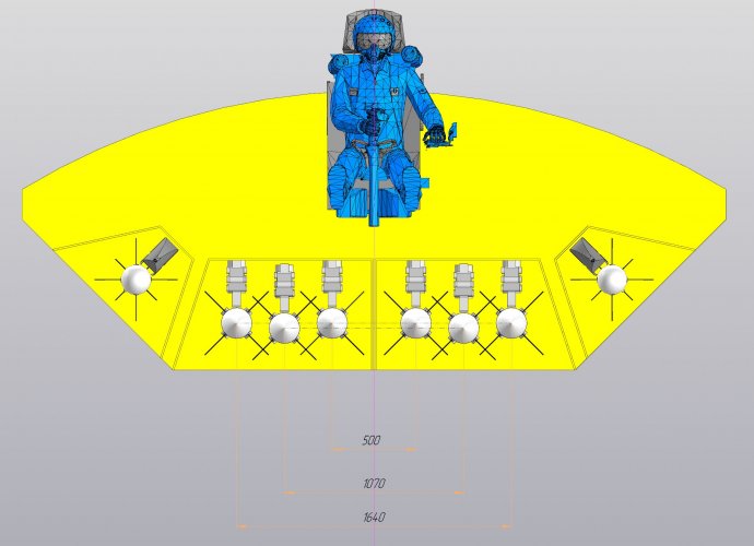
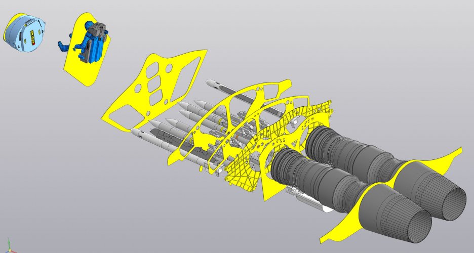
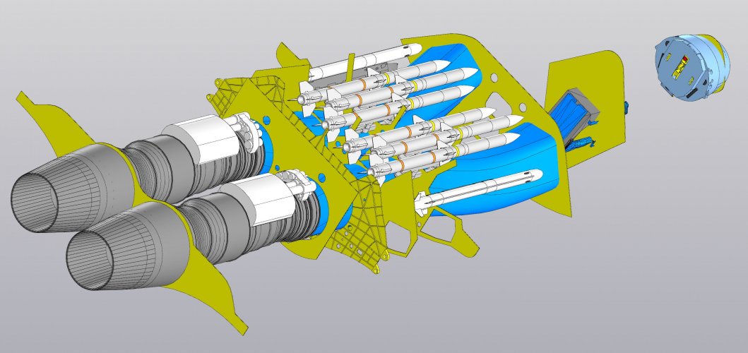
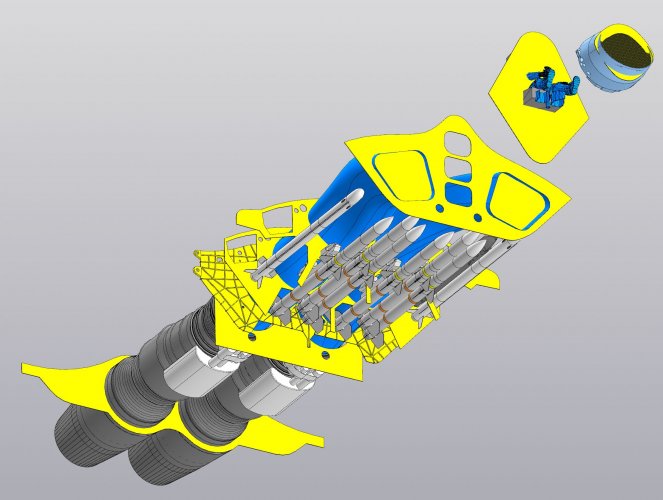
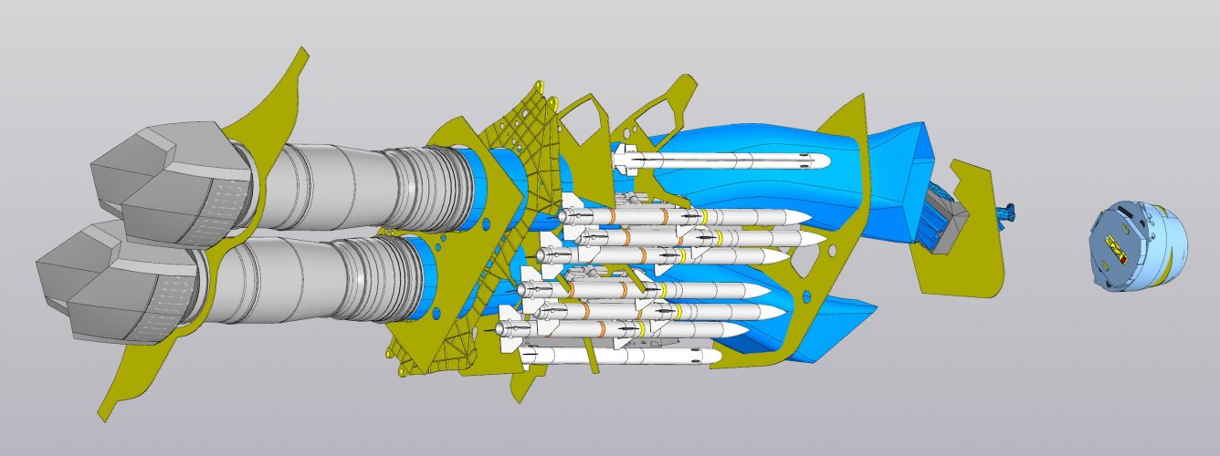
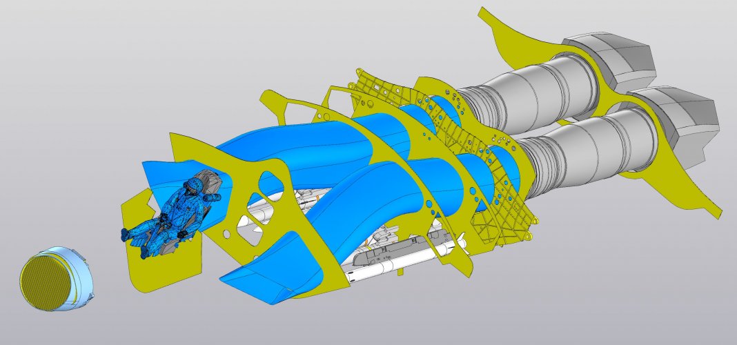
Silly question: you did remember to rotate the AMRAAM wingspan to 45deg, right? Width of 34.3cm that way.Online search for dimensions of F-22's IWB says it is classified. Anyways, 3D CADs can help in estimating current & new capacity, area, volume, etc of existing & new jets. Diagrams on internet are not 100% accurate, small adjustments needed.
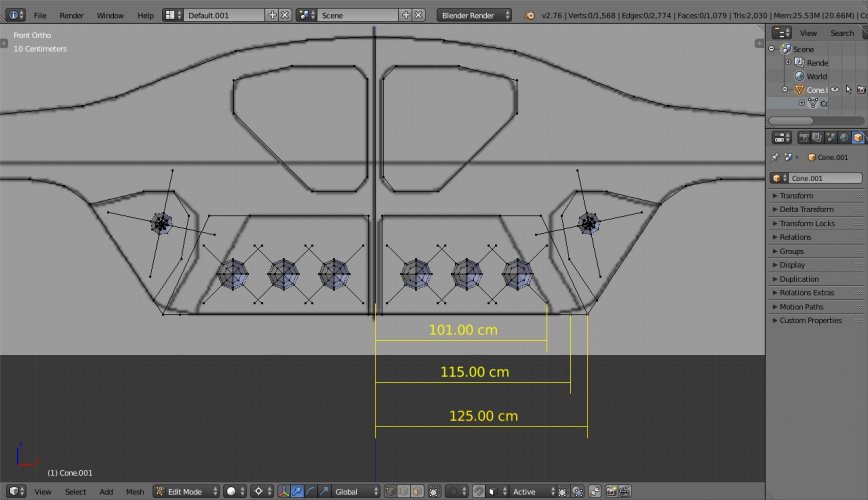
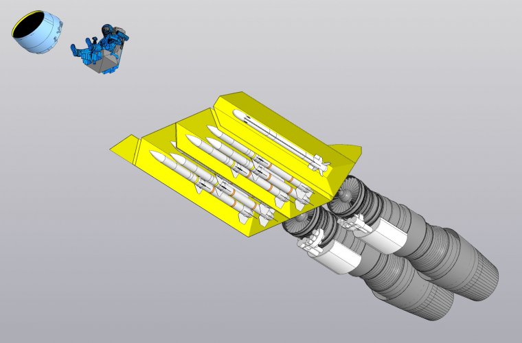
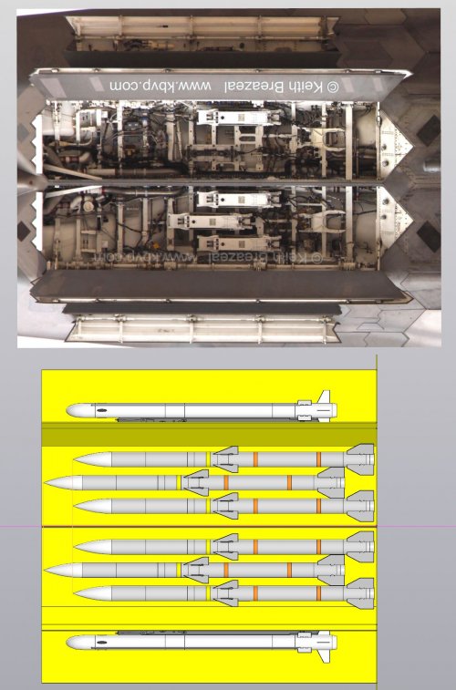
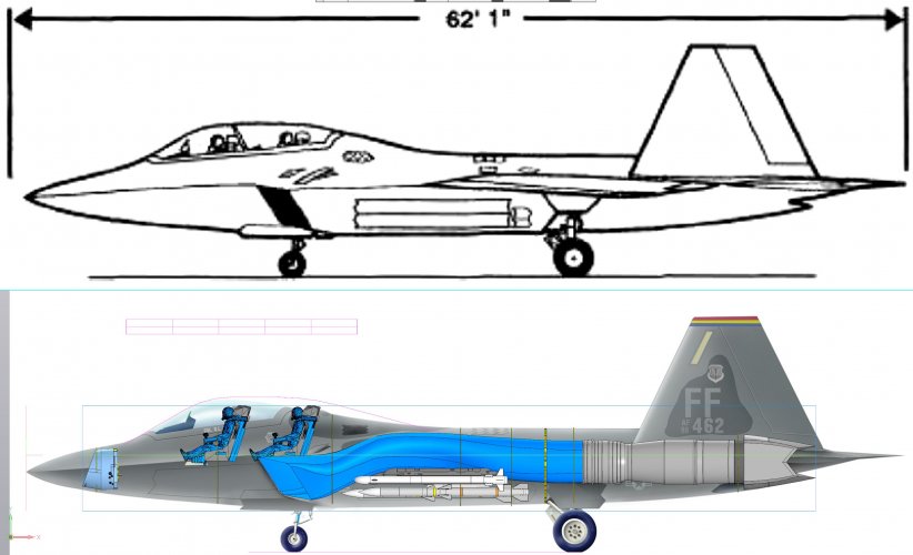
For example here i adjusted diagram dimensions then Blender view-port dimensions as per official specs, making the outline currently. But IWB in diagram looks short to accommodate staggered AIM-120 AMRAAMs.
AIM-120 AMRAAM length 3.66 m, body diameter 17.8 cm, wingspan 48.4 cm.
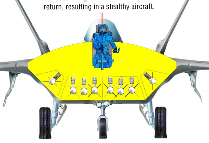
In Diagram each IWB hinge is is 104 cm from center.
We've to leave say 4 cm + 4cm in center for door edge support. This leaves 100cm wide IWB both sides.
When 3x AIM-120 AMRAAMs are staggered then they seem to occupy 4m length & 94 cm width, leaving just 3cm gap with side walls & 4cm gap between fin & body of adjacent AAM.
Silly question: you did remember to rotate the AMRAAM wingspan to 45deg, right? Width of 34.3cm that way.
Alright, just wanted a sanity check.Yes, the opposite tip-tip distance is quoted as wingspan in specs for an individual weapon, but they are rotated 45 degrees before mounting on launchers.
So here the adjacent fin tips would be 34.22cm apart.
I suspect that the gap between fin-tips and side walls is a little different. maybe 3cm between weapons and 4cm between side walls?When 3x AIM-120 AMRAAMs are staggered then they seem to occupy 4m length & 94 cm width, leaving just 3cm gap with side walls & 4cm gap between fin & body of adjacent AAM.
I suspect that the gap between fin-tips and side walls is a little different. maybe 3cm between weapons and 4cm between side walls?
I assume the drawings are based the titanium bulkhead photos and its redrawings.Online search for dimensions of F-22's IWB says it is classified. Anyways, 3D CADs can help in estimating current & new capacity, area, volume, etc of existing & new jets. Diagrams on internet are not 100% accurate, small adjustments needed.
For example here i adjusted diagram dimensions then Blender view-port dimensions as per official specs, making the outline currently. But IWB in diagram looks short to accommodate staggered AIM-120 AMRAAMs.
I assume the drawings are based the titanium bulkhead photos and its redrawings.
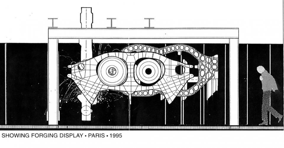
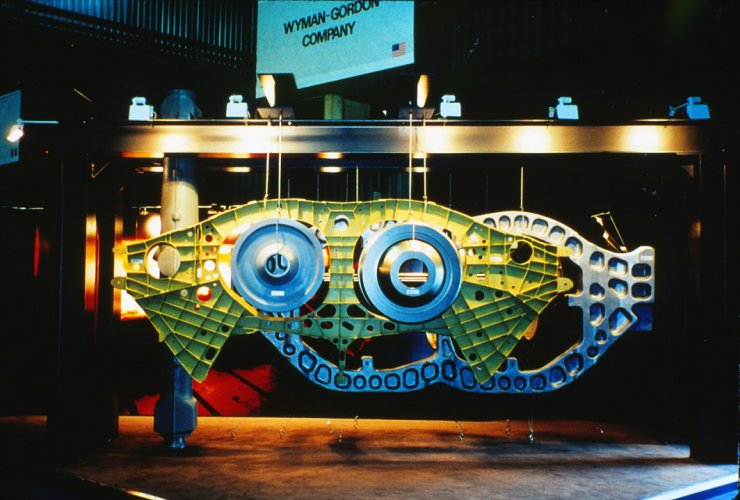
I don't think the drawings are accurate and might be based on skewed images. Then again the bulkhead shown was made before pre-production even has started. Google dates it back to 1995/7 Paris airshow displays (3 times in fact). That said the bulkheads are all located aft and don't represent the whole space of the bay.
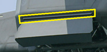
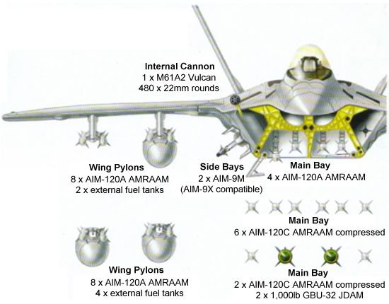
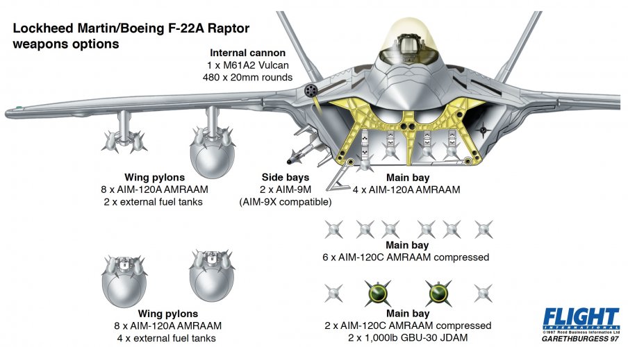
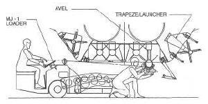
Hi. Gareth Burgess here, the Flight International technical artist who drew the the original F-22 weapons load drawing as shown above by Seragina.There're many drawings of F-22 online. Some have cross sections. I selected 1 of them.
After matching pixels with dimensions, in drawing itself the IWB was short for staggered AAMs. Now even the SWB also doesn't match.
Inaccurate drawings are ok for articles, casual depictions & making outline.
But they need manual rectification for accurate work.
Currently in diagram, the farthest AIM-120's fin is 101 cm from center.
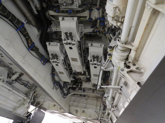
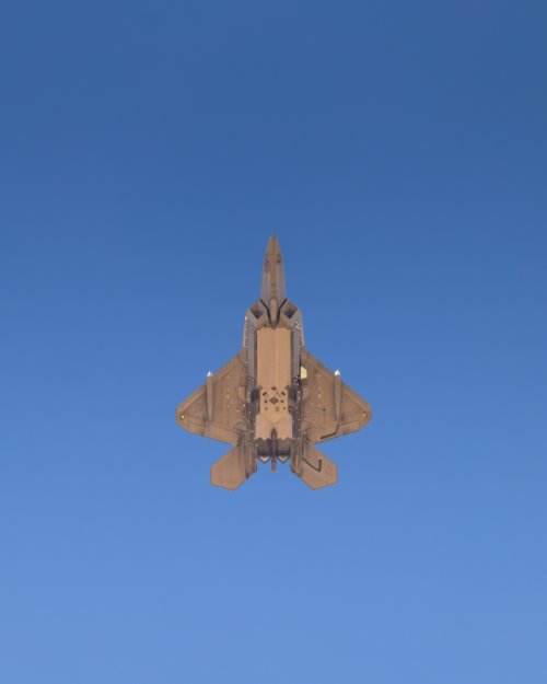
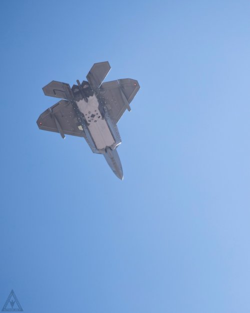
From real pics, considering space for hinge & its drive motor, the door edge could be around 115 cm from center.
Then there is a thin aux-door to cover hinge gap, so add say 5 cm more.
View attachment 818673
So at around 120 cm the belly edge would curve up towards SWB.
The belly & SWB surfaces would meet around say 125 cm from center.
But the diagram's SWB doesn't match with AIM-9L/M dimensions.
So this entire CAD based on inaccurate diagram is inaccurate & needs many small adjustments.
I'll try to find a high resolution head-on pic taken from far distance to superimpose & check.
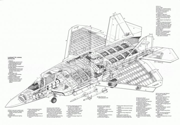
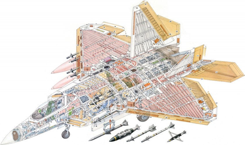
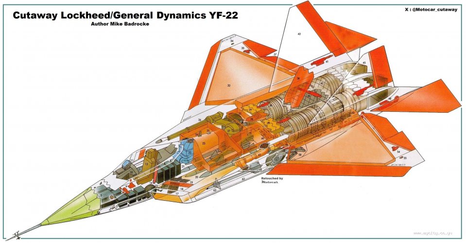
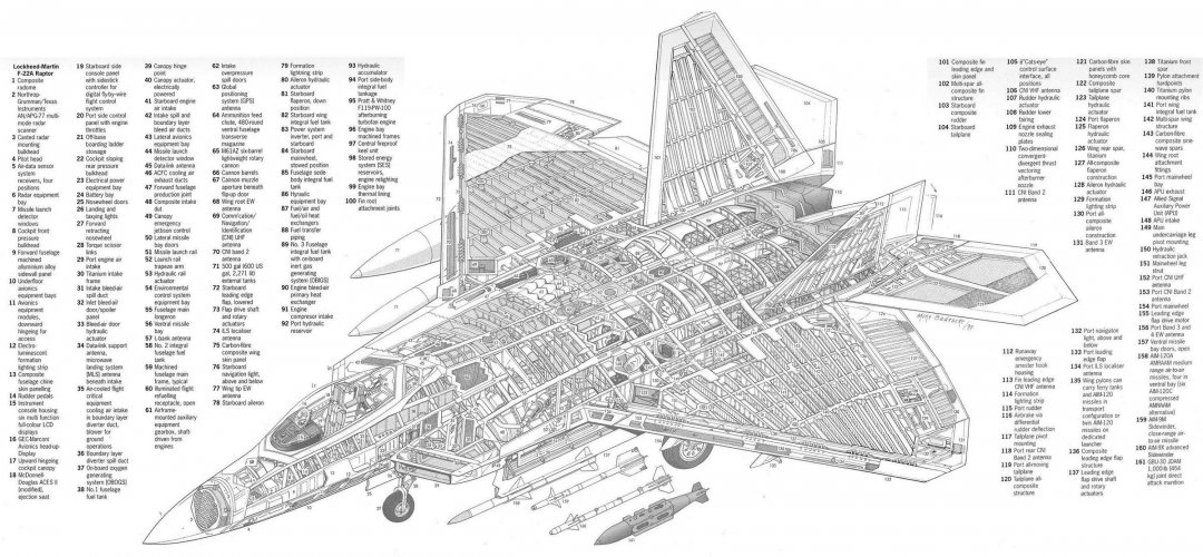
This appeared in the Flight International 1997 F-22 Supplement to support the cutaway drawing produced by Giuseppe 'Joe' Picarella.
Hi. In 2000, Flight produced a JSF supplement around the time of the JSF fly-offs and prior to the selection of the X-35. We tended to do these supplements around major project milestones, like for the Eurofighter Typhoon, and F-18E/F as other examples.I remember those drawings and they were fantastic, Gareth, but I'm wondering has Flight published the same sort of drawings for the F-35?

ZX-81 codec, with a tape recorder to upload data.So what software will the tablet run?
Though Flight did publish an JSF supplement, I produced a micro cutaway of both the Boeing F-32 with addition of the rear horizontal stabilisers as it would have been in service, and the Lockheed Martin F-35 as it was configured at the time.
I also produced a set of full colour general arrangement drawings for each aircraft, including both full and scrap views of the CTOL, V/STOL, and CV variants. In this, with direct access to information supplied from Lockheed-Martin, I was able to produce the twin-seat CV variant drawing. Obviously looking at these drawings now, the F-35 evolved on from these to it's final production configurations.
ThanksBut ,I believe around 2003 both Joe P and Tim Bicheno-Brown produced a more detailed micro cutaway poster of the F-38B, showing from both above and another view from below, with a scrap view of the weapons bay and cockpit layout.
.but if you can get access to the 2003 issue of Flight, that might help you more.
I'll try to find it if I can, might take a day or two. Wait-outThanks
I wonder if any of these drawings have been posted in the F-35 and F-32 threads?
I library I visit semi-regularly might have them in it its' basement, do you know which 2003 issue they were published in, please?
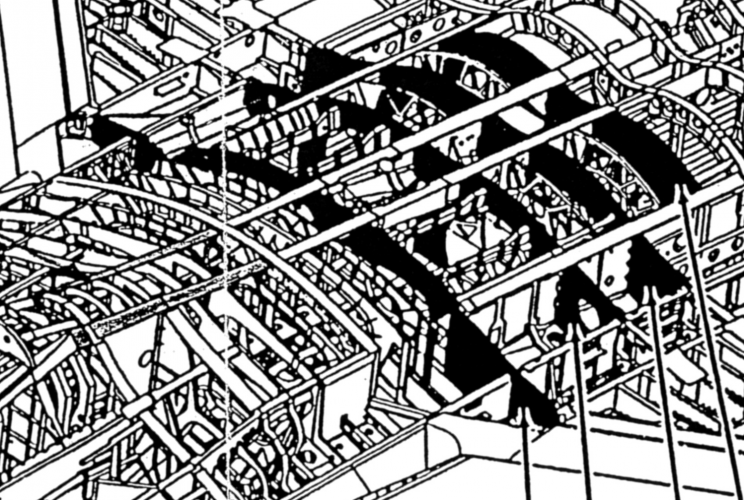
Hi. Gareth Burgess here, the Flight International technical artist who drew the the original F-22 weapons load drawing as shown above by Seragina.
My drawing is 100% accurate to one of the F-22's frames around the internal weapon bays. This appeared in the Flight International 1997 F-22 Supplement to support the cutaway drawing produced by Giuseppe 'Joe' Picarella. Joe produced the cutaway on site as Lockheed-Martin Marietta with major access to both the aircraft and CAD files.
Joe also created an underside schematic showing the weapons bays in detail. From files supplied directly from the Lockheed-Martin F-22 program I also produced the full colour general arrangement drawings of the plan, underside, front and port view. The weapons bay and armament fit diagram was produced from combines files from Lockheed-Martin direct.
These were then reviewed and signed off by Lockheed-Martin. I recall there was some weapons fits we had to not show at the time, though we had access to this information. Lockheed-Martin were great to work with, and gave our team amazing access to information to create the supplement.
I'm sorry to say, but the cross section used for you CAD drawing is incorrect, both in the centre pillar that divides the weapon bays, and also the internal engine intakes are incorrect in shape and position. I'm aware of the original GA drawing this is based on, which itself carries many inaccuracies. Hopefully the attached better resolution image of the internal frame will be of more use to you for the basis of your drawings as it is exactly based on a Lockheed-Martin CAD file.

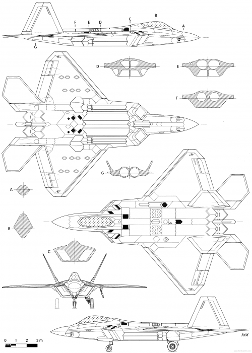
4-views from this (Czech L+K magazine I presume) are redrafted from official LM 1997 F/A-22 Media Guide (just like these) with probably an attempt to add some details from photos. Cross-sections are pure artist speculation pretty wrong in many places as I see. Media Guide still had some very rough IWB cross-section line CAD drawing.The drawings i used to outline my CAD is attached.

Looks like ASRAAM.Which AAM is there in SWB?
Yes well, thank you. Hope the drawing helps. Enjoy.Hello, hope you're doing well.
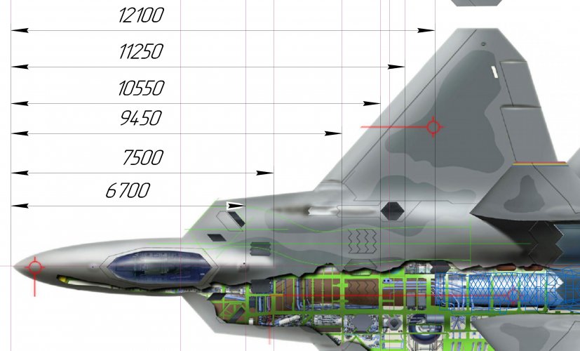
The drawings i used to outline my CAD is attached.
The artist's initials are in lower right corner "Ja M" & website blueprint "www.the-blueprints.com".
This diagram has all orthographic views (front, side, top, bottom), so i found it best to outline, but it is not 100% accurate w.r.t. IWB, cross sections, which need to be expanded a little.
I'll try your diagram superimposition also.
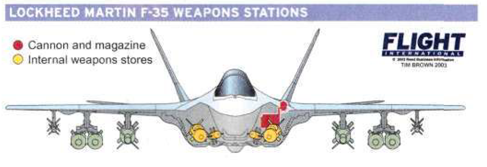
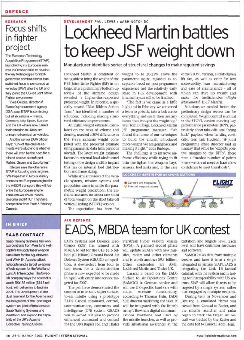
Apologies, I don't think I have the 2003 issue it came from, I did find this from P16, 25-31 March 2003.Thanks
I wonder if any of these drawings have been posted in the F-35 and F-32 threads?
I library I visit semi-regularly might have them in it its' basement, do you know which 2003 issue they were published in, please?
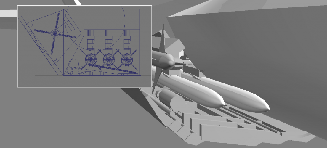
Are those angles on the weapons in the IWBs fairly accurate? If so, LockMart really twisted those all around to make it all fit.Apologies, I don't think I have the 2003 issue it came from, I did find this from P16, 25-31 March 2003.
Sorry I know this is the F-22 thread not f-35 so off topic, but here is the page and graphic up close for you. Again sorry for the low quality, but might be of use/interest.
I didn't produce the drawing so I couldn't tell you 100pc, sorry. However, based on experience of our artwork workflow and how we produced it, I would expect this was produced directly from Lockheed-Martin source material. No artistic twist to it, more than likely as the JSF program supplied the visual, probably to Paul who was based in the US and wrote the article. I recall there was some major 'twisting and pulling' so to speak to get stores to fit the internal dimensions and still be deployable without taking out another munition, launch rails, bay door(s), or the underside of the aircraft. Fun times!Are those angles on the weapons in the IWBs fairly accurate? If so, LockMart really twisted those all around to make it all fit.
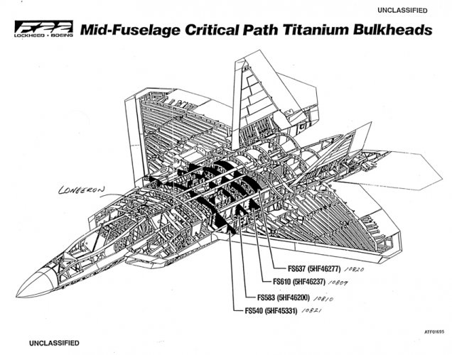
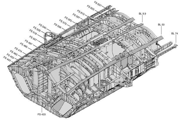
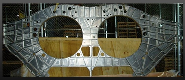
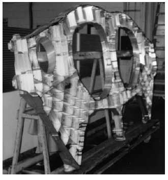
I was able to produce the twin-seat CV variant drawing.