
You are using an out of date browser. It may not display this or other websites correctly.
You should upgrade or use an alternative browser.
You should upgrade or use an alternative browser.
Larger British light fleet carriers?
- Thread starter Lascaris
- Start date
orlovsky
I really should change my personal text
- Joined
- 28 May 2016
- Messages
- 268
- Reaction score
- 570
It's the reason why the c-11 with just 6 or 12ft length over the bs5a has ~12kts more endspeed.Higher steam pressure... didn't knew about that parameter (another one, just to complicate the matter even further !).
The RN catapults had probably 300-400 psi, for this the bs5a is not bad at all...

Last edited:
orlovsky
I really should change my personal text
- Joined
- 28 May 2016
- Messages
- 268
- Reaction score
- 570
We could do with a bit more information on the French boilers and plant used in the Clemenceau class
Indret boilers, 640 psi. Indret is the navy establishment where they were built. The French went for high pressure as the US in contrast to the British; seems to have been a domestic development.
Accumulators 550 psi. Volume 2x27m3 per catapult. According to Moulin, 200-300 kg of steam per launch.
orlovsky
I really should change my personal text
- Joined
- 28 May 2016
- Messages
- 268
- Reaction score
- 570
Also interesting in Moulin: Initially a 4 shaft arrangement was planned for the clems, but they managed two shafts with 126000 hp and this saved 3000 tons weight. (Partially?) explains why the Clems were so light for their size, especially compared to the WWII designs.
Audacious: 4 shaft, 152000hp
Essex: 4 shaft, 150000hp
CVA-01: 3 shaft, 135000hp
Audacious: 4 shaft, 152000hp
Essex: 4 shaft, 150000hp
CVA-01: 3 shaft, 135000hp
while I was looking for the info on the boilers that Orlovsky posted... I came across this and on the lower left side the drawings are worth the click! https://naval-encyclopedia.com/cold-war/france/clemenceau-class-aircraft-carriers.php
The British did have higher pressure boilers available in the 50's but did not use them in the RN. SS Canberra a P&O liner built in the mid to late 50's had 750 PSI boilers for her turbo-electric drive. My gut is saying that would be useful but probably exceed G loads on some airframes.. lolWe could do with a bit more information on the French boilers and plant used in the Clemenceau class
Indret boilers, 640 psi. Indret is the navy establishment where they were built. The French went for high pressure as the US in contrast to the British; seems to have been a domestic development.
Accumulators 550 psi. Volume 2x27m3 per catapult. According to Moulin, 200-300 kg of steam per launch.
My understanding is that on Clem basic hull (maxed out for Verdun and later for CdG) the catapult vs lift vs parking area is all wrong. CdG has an issue of that kind that prevents launching Rafales while landing other Rafales, can't remember exactly.
Coming back to this comment as it’s an oft repeated misunderstanding of how cyclic deck ops work. The Clemenceau and CdG designs are actually quite efficient for air operations - certainly better any of the WW2 mods (Essex, Hermes, Victorious, Ark Royal.. which shouldn’t be a surprise).
This boils down to several features that are *incompatible* with simultaneous launch & recovery but that instead support better cyclic ops:
1) Waist catapult + Bow cat to port = Large deck park (for up to 15 aircraft with both cats clear, up to ~24 aircraft with landing area and waist cat clear)
2) Space for 4-6 alert/spare/tanker aircraft with easy access to both catapults
3) Both lifts clear of the landing area and at least 1x lift clear of the catapults so as not to interrupt air ops when moving aircraft to/from the hangar
4) Good access from the lifts directly to the catapults and to multiple corners of the hangar (especially CdG) which reduces the amount of respotting required
All the above are much more important for sortie generation and flexibility than the ability to simultaneously launch & recover 2 aircraft.
Last edited:
- Joined
- 21 May 2006
- Messages
- 3,002
- Reaction score
- 2,283
I second that ArchibaldThank you for that, very enlightening.
Regards
Pioneer
orlovsky
I really should change my personal text
- Joined
- 28 May 2016
- Messages
- 268
- Reaction score
- 570
Both designs got a lot of unfounded criticism to the extent that it is really difficult to get to the facts.All the above are much more important for sortie generation and flexibility than the ability to simultaneously launch & recover 2 aircraft.
What I am wondering: the bow cat is so far forward and clear of the landing area that simulteneous ops would be almost possible. Was this planned for with shorter catapults and then given up?
As with an arrangement as on CdG, the bow cat could be much longer?
BlackBat242
OK, I changed my personal text ;)
- Joined
- 10 April 2013
- Messages
- 1,482
- Reaction score
- 4,302
UK Admiralty 3-drum 400 psi 700° Colossus, MajesticWe could do with a bit more information on the French boilers and plant used in the Clemenceau class
Indret boilers, 640 psi. Indret is the navy establishment where they were built. The French went for high pressure as the US in contrast to the British; seems to have been a domestic development.
Accumulators 550 psi. Volume 2x27m3 per catapult. According to Moulin, 200-300 kg of steam per launch.
# # 400 psi 700° Centaur
# # 400 psi 600° Ark Royal, Eagle
FW ? 440 psi 750° Victorious (1958+)
Y102A 1-drum 700 psi 950° County (DDG)
# # 650 psi 850° Daring
Y100 1-drum 450 psi 850° Type 12
Y136 1-drum 550 psi 850° early Leander
Y160 1-drum 550 psi 850° Leander
USA BW pressurized 1,200 psi 950° C. F. Adams, Forrest Sherman
CE, FW pressurized* 1,200 psi 950° Brooke, Knox
CE, FW pressurized* 1,200 psi 950° Kitty Hawk, Saratoga/Ranger/Independence
BW, CE, FW unpress. 615/600 psi 900° Forrestal (only), Midway, Essex, Iowa
BW, CE, FW unpress. 600 psi 900° Gearing, Sumner, Fletcher
BW, CE, FW unpress. 600 psi 900° Thomaston, Anchorage, Austin,
BW, CE, FW unpress. 600 psi 900° Iwo Jima , Tarawa
* later altered to unpressurized
Babcock & Wilcox
Combustion Engineering
Foster Wheeler
C7, C11-1, C11-2, C13-0, and C13-1 are 520psi, while C13-2 is 450psi.
Track lengths: C-13-0 = 264 ft. 10"; C-13-1 & C-13-2 = 324 ft. 10"
C-13-0 is dry accumulator type, all other C-13 variants are wet accumulator types.
Each C-13-1 cat shot requires ~615 kg / 1,350 pounds of steam.
C-13-2 shots require ~1,000 kg / 2,200 pounds of steam.
Primary difference between C-13-1 and C-13-2 is that -2 has 21" diameter power cylinders vice 18".
France: CdG 435 psi
Each C-13-3 cat shot requires ~1000 kg / 2,200 pounds of steam.
Last edited:
I was always curious about the possibility of installing a side lift in a Colossus class. When there were plans to modernize 25 de Mayo, besides changing the engines, there were talks with an american about a side lift, to compensate the loss of the rear lift, that has to be welded to stand the weight of the Super Etendards landing.The Admiralty looked at installing a side lift on Victorious but quickly concluded that, at hangar deck level, the ship had insufficient freeboard. To have fitted one would have meant it being damaged in heavy seas and/or water entering the hangar deck itself. Not good news for any carrier due to the free surface effect.
In Ark Royal, the side lift only accessed the upper hangar. Again a lack of freeboard precluded it being extended down to access the lower hangar. It had to be removed when she was Phantomised in the 1960s when the waist catapult was fitted over the space it occupied.
The Centaur design began life with a bit more freeboard at hangar deck level allowing Hermes to have aside lift fitted in her redesign.
Trying to move the forward lift on these ships either port or starboard causes all sorts of headaches. There are solid steel walls either side that incorporate the raising/lowering chain gear and compartments outside those just under the flight deck that contain the motors to power them.
And these are “closed hangar” ships with compartments between the hangar wall and the ship’s side. The lifts themselves are more or less on the hangar centreline. So on Victorious, as reconstructed, you have a forward lift 40ft wide sitting in a hangar that is 62ft wide. That lift can only be accessed from forward and aft. So you are limited as to how far sideways you can move it without moving the hangar wall further out for a sufficient distance to take in the lift, and the space you need to manoeuvre an aircraft onto it. And remember, unlike an Essex or a Midway class, this is all structural steel work adding to the overall strength of the ship’s hull.
In Ark & Eagle the forward lift was 44ft wide in a 67ft wide hangar.
Hermes’ hangar was 62ft wide.
The Essex class were far easier to modify postwar because the main strength deck was the hangar deck, not the flight deck as in British carriers. Their hangar was superstructure, and much easier to modify. The biggest problem in them was relocating, where necessary, the various expansion joints in the hangar structure as longer catapults were fitted and lifts moved from the centreline. An Essex was an “open hanger” ship where the hangar itself, except around the island, extended the full width of the ship.
So a cuestion for those with knowledge: it would have been possible to lengthen the ship with a plug that has the side lift built in ( with all the structural aspects considered in the design) adfing bulges to the hull to compensate for the increase in lenght and add stability?
Sorrry, I meant an American ship design firm…I was always curious about the possibility of installing a side lift in a Colossus class. When there were plans to modernize 25 de Mayo, besides changing the engines, there were talks with an american about a side lift, to compensate the loss of the rear lift, that has to be welded to stand the weight of the Super Etendards landing.The Admiralty looked at installing a side lift on Victorious but quickly concluded that, at hangar deck level, the ship had insufficient freeboard. To have fitted one would have meant it being damaged in heavy seas and/or water entering the hangar deck itself. Not good news for any carrier due to the free surface effect.
In Ark Royal, the side lift only accessed the upper hangar. Again a lack of freeboard precluded it being extended down to access the lower hangar. It had to be removed when she was Phantomised in the 1960s when the waist catapult was fitted over the space it occupied.
The Centaur design began life with a bit more freeboard at hangar deck level allowing Hermes to have aside lift fitted in her redesign.
Trying to move the forward lift on these ships either port or starboard causes all sorts of headaches. There are solid steel walls either side that incorporate the raising/lowering chain gear and compartments outside those just under the flight deck that contain the motors to power them.
And these are “closed hangar” ships with compartments between the hangar wall and the ship’s side. The lifts themselves are more or less on the hangar centreline. So on Victorious, as reconstructed, you have a forward lift 40ft wide sitting in a hangar that is 62ft wide. That lift can only be accessed from forward and aft. So you are limited as to how far sideways you can move it without moving the hangar wall further out for a sufficient distance to take in the lift, and the space you need to manoeuvre an aircraft onto it. And remember, unlike an Essex or a Midway class, this is all structural steel work adding to the overall strength of the ship’s hull.
In Ark & Eagle the forward lift was 44ft wide in a 67ft wide hangar.
Hermes’ hangar was 62ft wide.
The Essex class were far easier to modify postwar because the main strength deck was the hangar deck, not the flight deck as in British carriers. Their hangar was superstructure, and much easier to modify. The biggest problem in them was relocating, where necessary, the various expansion joints in the hangar structure as longer catapults were fitted and lifts moved from the centreline. An Essex was an “open hanger” ship where the hangar itself, except around the island, extended the full width of the ship.
So a cuestion for those with knowledge: it would have been possible to lengthen the ship with a plug that has the side lift built in ( with all the structural aspects considered in the design) adfing bulges to the hull to compensate for the increase in lenght and add stability?
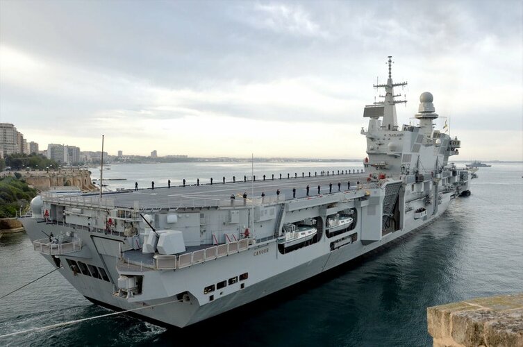
I am not entirely sure where the floor of the hangar IS in this picture... you need about 24 feet/7.3 meters of room between the lift and the sea under it for safety.
Is about at the same level of the boat bays floor. I measured it on the plans of the class, and that is about 17/19 feet over the water, if not mistaken ( will double check tomorrow). The Itslian carrier Cavour has a lateral lift with about that clearance when in the down position, but it is fairly well protected around. So it can be done, I think.Sorrry, I meant an American ship design firm…I was always curious about the possibility of installing a side lift in a Colossus class. When there were plans to modernize 25 de Mayo, besides changing the engines, there were talks with an american about a side lift, to compensate the loss of the rear lift, that has to be welded to stand the weight of the Super Etendards landing.The Admiralty looked at installing a side lift on Victorious but quickly concluded that, at hangar deck level, the ship had insufficient freeboard. To have fitted one would have meant it being damaged in heavy seas and/or water entering the hangar deck itself. Not good news for any carrier due to the free surface effect.
In Ark Royal, the side lift only accessed the upper hangar. Again a lack of freeboard precluded it being extended down to access the lower hangar. It had to be removed when she was Phantomised in the 1960s when the waist catapult was fitted over the space it occupied.
The Centaur design began life with a bit more freeboard at hangar deck level allowing Hermes to have aside lift fitted in her redesign.
Trying to move the forward lift on these ships either port or starboard causes all sorts of headaches. There are solid steel walls either side that incorporate the raising/lowering chain gear and compartments outside those just under the flight deck that contain the motors to power them.
And these are “closed hangar” ships with compartments between the hangar wall and the ship’s side. The lifts themselves are more or less on the hangar centreline. So on Victorious, as reconstructed, you have a forward lift 40ft wide sitting in a hangar that is 62ft wide. That lift can only be accessed from forward and aft. So you are limited as to how far sideways you can move it without moving the hangar wall further out for a sufficient distance to take in the lift, and the space you need to manoeuvre an aircraft onto it. And remember, unlike an Essex or a Midway class, this is all structural steel work adding to the overall strength of the ship’s hull.
In Ark & Eagle the forward lift was 44ft wide in a 67ft wide hangar.
Hermes’ hangar was 62ft wide.
The Essex class were far easier to modify postwar because the main strength deck was the hangar deck, not the flight deck as in British carriers. Their hangar was superstructure, and much easier to modify. The biggest problem in them was relocating, where necessary, the various expansion joints in the hangar structure as longer catapults were fitted and lifts moved from the centreline. An Essex was an “open hanger” ship where the hangar itself, except around the island, extended the full width of the ship.
So a cuestion for those with knowledge: it would have been possible to lengthen the ship with a plug that has the side lift built in ( with all the structural aspects considered in the design) adfing bulges to the hull to compensate for the increase in lenght and add stability?
I am not entirely sure where the floor of the hangar IS in this picture... you need about 24 feet/7.3 meters of room between the lift and the sea under it for safety.

Attachments
Here are the original plans for HMS Colossus… this should allow you to measure the height from the keel & waterline to the hangar floor.So a cuestion for those with knowledge: it would have been possible to lengthen the ship with a plug that has the side lift built in ( with all the structural aspects considered in the design) adfing bulges to the hull to compensate for the increase in lenght and add stability?
French Aircraft Carrier ARROMANCHES as Build 1943 (ex. HMS Colossus) | 3DHISTORY.DE
French Aircraft Carrier ARROMANCHES as Build 1943 (ex. HMS Colossus) – 9 Sheets Scale 1/200, Scale 1/100 and Scale 1/20 (This sets of drawings were...
3dhistory.de
Also if you download the high resolution images at the link above you may be able to read the internal layout clearly enough to determine where the steam turbine machinery rooms are… ideally you would want to cut the hull ahead of the forward machinery room (in order to leave the propeller shaft trunks the same).
Note that none of this would solve 25 de Mayo’s biggest weakness: the slow ship speed and weak catapult which would limit aircraft launch weights…
Attachments
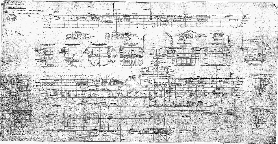
Thank you! I have those. I used the cutaway of Melbourne to msrk the boiler rooms ( red), the uptakes ( black), flotation line ( FL-blue) and hangar floor ( HF-white). Used the vertical view of 25 de Mayo to constrain where to place the lift ( in white) so for it not to interfere with the uptskes, or with the deployment mechanism for tbe emergency arresting net. 25 de Mayoo needed it as the rear elevator was welded as to whistand the impsct of the SUE landing eith their higher V.Here are the original plans for HMS Colossus… this should allow you to measure the height from the keel & waterline to the hangar floor.So a cuestion for those with knowledge: it would have been possible to lengthen the ship with a plug that has the side lift built in ( with all the structural aspects considered in the design) adfing bulges to the hull to compensate for the increase in lenght and add stability?
French Aircraft Carrier ARROMANCHES as Build 1943 (ex. HMS Colossus) | 3DHISTORY.DE
French Aircraft Carrier ARROMANCHES as Build 1943 (ex. HMS Colossus) – 9 Sheets Scale 1/200, Scale 1/100 and Scale 1/20 (This sets of drawings were...3dhistory.de
Also if you download the high resolution images at the link above you may be able to read the internal layout clearly enough to determine where the steam turbine machinery rooms are… ideally you would want to cut the hull ahead of the forward machinery room (in order to leave the propeller shaft trunks the same).
Note that none of this would solve 25 de Mayo’s biggest weakness: the slow ship speed and weak catapult which would limit aircraft launch weights…
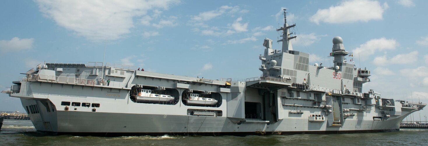
Height from FL to HF is 17feet ( can be 18) wich is a bit more than 5 meters. This is the same height of the HF in the Italian Cavour carrier. They have the elevator encases in a protective structure, that I imagine act as a wave diverter, and will also probsbly be needed as structural reinforcmrnt.
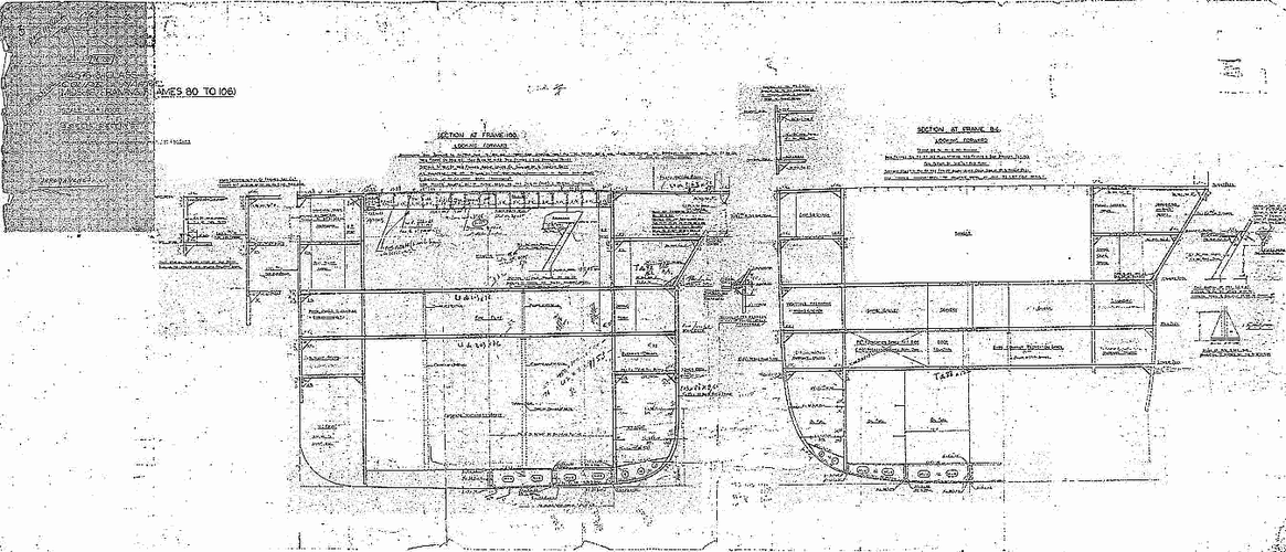
Red arrows show the section wehere a prismatic hull plug can be inserted, if lenghtening can be an option. That would imply either moving machinery aft, if you want to keep your shaft lenghts the same, and implying a relocation of the iptakes ( too complicated?) or adopting diesel electric: you can leave the relative position of your engine rooms the same (with the aft one relocated on the plug) so as not to modify the island position) and cables running to the electrical engines, no llng shafts, etc. more hangar spsce, more deck space, maybe a waist catapult..lot of possibilities. I think in this case bulges would be needed for stability and structural rigidity, as the b/l ratio would go beyond 8, depending on the length of the plug.
Sorry about the misspellings, need a bigger iphone..Thank you! I have those. I used the cutaway of Melbourne to msrk the boiler rooms ( red), the uptakes ( black), flotation line ( FL-blue) and hangar floor ( HF-white). Used the vertical view of 25 de Mayo to constrain where to place the lift ( in white) so for it not to interfere with the uptskes, or with the deployment mechanism for tbe emergency arresting net. 25 de Mayoo needed it as the rear elevator was welded as to whistand the impsct of the SUE landing eith their higher V.Here are the original plans for HMS Colossus… this should allow you to measure the height from the keel & waterline to the hangar floor.So a cuestion for those with knowledge: it would have been possible to lengthen the ship with a plug that has the side lift built in ( with all the structural aspects considered in the design) adfing bulges to the hull to compensate for the increase in lenght and add stability?
French Aircraft Carrier ARROMANCHES as Build 1943 (ex. HMS Colossus) | 3DHISTORY.DE
French Aircraft Carrier ARROMANCHES as Build 1943 (ex. HMS Colossus) – 9 Sheets Scale 1/200, Scale 1/100 and Scale 1/20 (This sets of drawings were...3dhistory.de
Also if you download the high resolution images at the link above you may be able to read the internal layout clearly enough to determine where the steam turbine machinery rooms are… ideally you would want to cut the hull ahead of the forward machinery room (in order to leave the propeller shaft trunks the same).
Note that none of this would solve 25 de Mayo’s biggest weakness: the slow ship speed and weak catapult which would limit aircraft launch weights…
Height from FL to HF is 17feet ( can be 18) wich is a bit more than 5 meters. This is the same height of the HF in the Italian Cavour carrier. They have the elevator encases in a protective structure, that I imagine act as a wave diverter, and will also probsbly be needed as structural reinforcmrnt.
Red arrows show the section wehere a prismatic hull plug can be inserted, if lenghtening can be an option. That would imply either moving machinery aft, if you want to keep your shaft lenghts the same, and implying a relocation of the iptakes ( too complicated?) or adopting diesel electric: you can leave the relative position of your engine rooms the same (with the aft one relocated on the plug) so as not to modify the island position) and cables running to the electrical engines, no llng shafts, etc. more hangar spsce, more deck space, maybe a waist catapult..lot of possibilities. I think in this case bulges would be needed for stability and structural rigidity, as the b/l ratio would go beyond 8, depending on the length of the plug.
About the low speed: 25 de Mayo was going to be reengined, with a CODOG plant, because of the mounting problems with the powerplant resulting in the low speed (that is why Banzai Night didn’t happen in 1982). During that refit is where the placement of a side lift was being considered, to compensate for the aft one being deactivated. The catapult per se was not that weak, actually it was the most potent catapult installed in any Majestic/Colossus. Maybe the new poweplant would have made possible to replace it with a higher pressure catapult with the same stroke lenght (total was 199 feet, stroke lenght 175 feet). I never read that a replacement gor the catapult was being considered though.Sorry about the misspellings, need a bigger iphone..Thank you! I have those. I used the cutaway of Melbourne to msrk the boiler rooms ( red), the uptakes ( black), flotation line ( FL-blue) and hangar floor ( HF-white). Used the vertical view of 25 de Mayo to constrain where to place the lift ( in white) so for it not to interfere with the uptskes, or with the deployment mechanism for tbe emergency arresting net. 25 de Mayoo needed it as the rear elevator was welded as to whistand the impsct of the SUE landing eith their higher V.Here are the original plans for HMS Colossus… this should allow you to measure the height from the keel & waterline to the hangar floor.So a cuestion for those with knowledge: it would have been possible to lengthen the ship with a plug that has the side lift built in ( with all the structural aspects considered in the design) adfing bulges to the hull to compensate for the increase in lenght and add stability?
French Aircraft Carrier ARROMANCHES as Build 1943 (ex. HMS Colossus) | 3DHISTORY.DE
French Aircraft Carrier ARROMANCHES as Build 1943 (ex. HMS Colossus) – 9 Sheets Scale 1/200, Scale 1/100 and Scale 1/20 (This sets of drawings were...3dhistory.de
Also if you download the high resolution images at the link above you may be able to read the internal layout clearly enough to determine where the steam turbine machinery rooms are… ideally you would want to cut the hull ahead of the forward machinery room (in order to leave the propeller shaft trunks the same).
Note that none of this would solve 25 de Mayo’s biggest weakness: the slow ship speed and weak catapult which would limit aircraft launch weights…
Height from FL to HF is 17feet ( can be 18) wich is a bit more than 5 meters. This is the same height of the HF in the Italian Cavour carrier. They have the elevator encases in a protective structure, that I imagine act as a wave diverter, and will also probsbly be needed as structural reinforcmrnt.
Red arrows show the section wehere a prismatic hull plug can be inserted, if lenghtening can be an option. That would imply either moving machinery aft, if you want to keep your shaft lenghts the same, and implying a relocation of the iptakes ( too complicated?) or adopting diesel electric: you can leave the relative position of your engine rooms the same (with the aft one relocated on the plug) so as not to modify the island position) and cables running to the electrical engines, no llng shafts, etc. more hangar spsce, more deck space, maybe a waist catapult..lot of possibilities. I think in this case bulges would be needed for stability and structural rigidity, as the b/l ratio would go beyond 8, depending on the length of the plug.

it looks to me like it is in the 20-ish feet range could be close to 24... if they were considering it we can assume that it is near enough to be workable. It will get you some more hangar area, probably enough for 2 aircraft.Is about at the same level of the boat bays floor. I measured it on the plans of the class, and that is about 17/19 feet over the water, if not mistaken ( will double check tomorrow). The Itslian carrier Cavour has a lateral lift with about that clearance when in the down position, but it is fairly well protected around. So it can be done, I think.View attachment 693020Sorrry, I meant an American ship design firm…I was always curious about the possibility of installing a side lift in a Colossus class. When there were plans to modernize 25 de Mayo, besides changing the engines, there were talks with an american about a side lift, to compensate the loss of the rear lift, that has to be welded to stand the weight of the Super Etendards landing.The Admiralty looked at installing a side lift on Victorious but quickly concluded that, at hangar deck level, the ship had insufficient freeboard. To have fitted one would have meant it being damaged in heavy seas and/or water entering the hangar deck itself. Not good news for any carrier due to the free surface effect.
In Ark Royal, the side lift only accessed the upper hangar. Again a lack of freeboard precluded it being extended down to access the lower hangar. It had to be removed when she was Phantomised in the 1960s when the waist catapult was fitted over the space it occupied.
The Centaur design began life with a bit more freeboard at hangar deck level allowing Hermes to have aside lift fitted in her redesign.
Trying to move the forward lift on these ships either port or starboard causes all sorts of headaches. There are solid steel walls either side that incorporate the raising/lowering chain gear and compartments outside those just under the flight deck that contain the motors to power them.
And these are “closed hangar” ships with compartments between the hangar wall and the ship’s side. The lifts themselves are more or less on the hangar centreline. So on Victorious, as reconstructed, you have a forward lift 40ft wide sitting in a hangar that is 62ft wide. That lift can only be accessed from forward and aft. So you are limited as to how far sideways you can move it without moving the hangar wall further out for a sufficient distance to take in the lift, and the space you need to manoeuvre an aircraft onto it. And remember, unlike an Essex or a Midway class, this is all structural steel work adding to the overall strength of the ship’s hull.
In Ark & Eagle the forward lift was 44ft wide in a 67ft wide hangar.
Hermes’ hangar was 62ft wide.
The Essex class were far easier to modify postwar because the main strength deck was the hangar deck, not the flight deck as in British carriers. Their hangar was superstructure, and much easier to modify. The biggest problem in them was relocating, where necessary, the various expansion joints in the hangar structure as longer catapults were fitted and lifts moved from the centreline. An Essex was an “open hanger” ship where the hangar itself, except around the island, extended the full width of the ship.
So a cuestion for those with knowledge: it would have been possible to lengthen the ship with a plug that has the side lift built in ( with all the structural aspects considered in the design) adfing bulges to the hull to compensate for the increase in lenght and add stability?
I am not entirely sure where the floor of the hangar IS in this picture... you need about 24 feet/7.3 meters of room between the lift and the sea under it for safety.
All in all it would have been smarter for the Argentines to buy Centaur or Victorious
True.. but I don’t think they were ever offered..it looks to me like it is in the 20-ish feet range could be close to 24... if they were considering it we can assume that it is near enough to be workable. It will get you some more hangar area, probably enough for 2 aircraft.Is about at the same level of the boat bays floor. I measured it on the plans of the class, and that is about 17/19 feet over the water, if not mistaken ( will double check tomorrow). The Itslian carrier Cavour has a lateral lift with about that clearance when in the down position, but it is fairly well protected around. So it can be done, I think.View attachment 693020Sorrry, I meant an American ship design firm…I was always curious about the possibility of installing a side lift in a Colossus class. When there were plans to modernize 25 de Mayo, besides changing the engines, there were talks with an american about a side lift, to compensate the loss of the rear lift, that has to be welded to stand the weight of the Super Etendards landing.The Admiralty looked at installing a side lift on Victorious but quickly concluded that, at hangar deck level, the ship had insufficient freeboard. To have fitted one would have meant it being damaged in heavy seas and/or water entering the hangar deck itself. Not good news for any carrier due to the free surface effect.
In Ark Royal, the side lift only accessed the upper hangar. Again a lack of freeboard precluded it being extended down to access the lower hangar. It had to be removed when she was Phantomised in the 1960s when the waist catapult was fitted over the space it occupied.
The Centaur design began life with a bit more freeboard at hangar deck level allowing Hermes to have aside lift fitted in her redesign.
Trying to move the forward lift on these ships either port or starboard causes all sorts of headaches. There are solid steel walls either side that incorporate the raising/lowering chain gear and compartments outside those just under the flight deck that contain the motors to power them.
And these are “closed hangar” ships with compartments between the hangar wall and the ship’s side. The lifts themselves are more or less on the hangar centreline. So on Victorious, as reconstructed, you have a forward lift 40ft wide sitting in a hangar that is 62ft wide. That lift can only be accessed from forward and aft. So you are limited as to how far sideways you can move it without moving the hangar wall further out for a sufficient distance to take in the lift, and the space you need to manoeuvre an aircraft onto it. And remember, unlike an Essex or a Midway class, this is all structural steel work adding to the overall strength of the ship’s hull.
In Ark & Eagle the forward lift was 44ft wide in a 67ft wide hangar.
Hermes’ hangar was 62ft wide.
The Essex class were far easier to modify postwar because the main strength deck was the hangar deck, not the flight deck as in British carriers. Their hangar was superstructure, and much easier to modify. The biggest problem in them was relocating, where necessary, the various expansion joints in the hangar structure as longer catapults were fitted and lifts moved from the centreline. An Essex was an “open hanger” ship where the hangar itself, except around the island, extended the full width of the ship.
So a cuestion for those with knowledge: it would have been possible to lengthen the ship with a plug that has the side lift built in ( with all the structural aspects considered in the design) adfing bulges to the hull to compensate for the increase in lenght and add stability?
I am not entirely sure where the floor of the hangar IS in this picture... you need about 24 feet/7.3 meters of room between the lift and the sea under it for safety.
All in all it would have been smarter for the Argentines to buy Centaur or Victorious
They were offered Implacable in the 50's, I don't know if they were approached by the UK to buy either but I would bet that if the UK had been asked they would have sold them on.True.. but I don’t think they were ever offered..it looks to me like it is in the 20-ish feet range could be close to 24... if they were considering it we can assume that it is near enough to be workable. It will get you some more hangar area, probably enough for 2 aircraft.Is about at the same level of the boat bays floor. I measured it on the plans of the class, and that is about 17/19 feet over the water, if not mistaken ( will double check tomorrow). The Itslian carrier Cavour has a lateral lift with about that clearance when in the down position, but it is fairly well protected around. So it can be done, I think.View attachment 693020Sorrry, I meant an American ship design firm…I was always curious about the possibility of installing a side lift in a Colossus class. When there were plans to modernize 25 de Mayo, besides changing the engines, there were talks with an american about a side lift, to compensate the loss of the rear lift, that has to be welded to stand the weight of the Super Etendards landing.The Admiralty looked at installing a side lift on Victorious but quickly concluded that, at hangar deck level, the ship had insufficient freeboard. To have fitted one would have meant it being damaged in heavy seas and/or water entering the hangar deck itself. Not good news for any carrier due to the free surface effect.
In Ark Royal, the side lift only accessed the upper hangar. Again a lack of freeboard precluded it being extended down to access the lower hangar. It had to be removed when she was Phantomised in the 1960s when the waist catapult was fitted over the space it occupied.
The Centaur design began life with a bit more freeboard at hangar deck level allowing Hermes to have aside lift fitted in her redesign.
Trying to move the forward lift on these ships either port or starboard causes all sorts of headaches. There are solid steel walls either side that incorporate the raising/lowering chain gear and compartments outside those just under the flight deck that contain the motors to power them.
And these are “closed hangar” ships with compartments between the hangar wall and the ship’s side. The lifts themselves are more or less on the hangar centreline. So on Victorious, as reconstructed, you have a forward lift 40ft wide sitting in a hangar that is 62ft wide. That lift can only be accessed from forward and aft. So you are limited as to how far sideways you can move it without moving the hangar wall further out for a sufficient distance to take in the lift, and the space you need to manoeuvre an aircraft onto it. And remember, unlike an Essex or a Midway class, this is all structural steel work adding to the overall strength of the ship’s hull.
In Ark & Eagle the forward lift was 44ft wide in a 67ft wide hangar.
Hermes’ hangar was 62ft wide.
The Essex class were far easier to modify postwar because the main strength deck was the hangar deck, not the flight deck as in British carriers. Their hangar was superstructure, and much easier to modify. The biggest problem in them was relocating, where necessary, the various expansion joints in the hangar structure as longer catapults were fitted and lifts moved from the centreline. An Essex was an “open hanger” ship where the hangar itself, except around the island, extended the full width of the ship.
So a cuestion for those with knowledge: it would have been possible to lengthen the ship with a plug that has the side lift built in ( with all the structural aspects considered in the design) adfing bulges to the hull to compensate for the increase in lenght and add stability?
I am not entirely sure where the floor of the hangar IS in this picture... you need about 24 feet/7.3 meters of room between the lift and the sea under it for safety.
All in all it would have been smarter for the Argentines to buy Centaur or Victorious
IIRC at that point in the late 60's Argentina still had a substantial amount of British IOU's from WW2.. they held about 300 million pounds of them at the end of the war.. they could have done a debt swap and not been out any actual cash.
Brazil tried doing that in 1952 - didn't work; the UK refused to accept it when Brazil was interested in replacing WWII equipment. UK wanted US Dollars, not a debt swap.IIRC at that point in the late 60's Argentina still had a substantial amount of British IOU's from WW2.. they held about 300 million pounds of them at the end of the war.. they could have done a debt swap and not been out any actual cash.
- Joined
- 27 September 2006
- Messages
- 6,417
- Reaction score
- 6,823
If you look at aircraft carriers from the 1950s onward you have a clear divide between:
carriers that can only operate Seahawks and Skyhawks.
carriers that can operate Phantoms and Buccaneers.
I omit vstol Harrier carriers as these are primarily ASW helicopter carriers (Invincible, Sea Control Ship, Garibaldi) with Harriers added.
The Light Fleets work fine with Seahawks and Venoms. India used Seahawks on Vikrant in war against Pakistan.
The F4 requires an Eagle sized carrier as a bare minimum.
France operates F8 and Etendard from Foch and Clemenceau and Super Etendard from De Gaulle. Neither option appealed to the RN who moved after 1966 to ASW carriers.
I have argued in other threads that the 1966 decision recognised that the SSN rather than the aircraft carrier was the UK's most effective way of sinking enemy ships globally. I still think that is true and would have preferred more Astutes to the two carriers we ordered in 1997.
Even the Falklands operation which is always quoted as the justification for RN aircraft carriers could have been avoided by the timely deployment of SSN.
Land based airpower in the Gulf, Balkans and Afghanistan played the main part with carrier airpower being used simply because the carriers were there.
An earlier recognition by the RN that carriers were an expensive luxury would have seen them scrapped in the early 60s as SSN became available.
Supposedly Bonaventure was partially paid for with Ontario Cheddar.Brazil tried doing that in 1952 - didn't work; the UK refused to accept it when Brazil was interested in replacing WWII equipment. UK wanted US Dollars, not a debt swap.IIRC at that point in the late 60's Argentina still had a substantial amount of British IOU's from WW2.. they held about 300 million pounds of them at the end of the war.. they could have done a debt swap and not been out any actual cash.
From "The History of Canadian Naval Aviation 1918-1962" by Kealy & Russell, Chapter IX HMCS Bonaventure.Supposedly Bonaventure was partially paid for with Ontario Cheddar.Brazil tried doing that in 1952 - didn't work; the UK refused to accept it when Brazil was interested in replacing WWII equipment. UK wanted US Dollars, not a debt swap.IIRC at that point in the late 60's Argentina still had a substantial amount of British IOU's from WW2.. they held about 300 million pounds of them at the end of the war.. they could have done a debt swap and not been out any actual cash.
"During negotiations with the Royal Navy the Honourable Mr. Brooke Claxton, then Minister of National Defence, proposed that the United Kingdom should be asked to spend the purchase money, 21 mil-lion dollars, on Canadian cheese. Owing to an acute shortage of gold and dollar reserves the British regret-fully had to put the lid on this savoury suggestion."
The final cost of Bonaventure, excluding provision of certain North American equipment came to approx CDN$31m.
that is good to knowBrazil tried doing that in 1952 - didn't work; the UK refused to accept it when Brazil was interested in replacing WWII equipment. UK wanted US Dollars, not a debt swap.IIRC at that point in the late 60's Argentina still had a substantial amount of British IOU's from WW2.. they held about 300 million pounds of them at the end of the war.. they could have done a debt swap and not been out any actual cash.
Both I believe Tony German and Snowie in their respective books mention it and both dismiss it as rumor. .From "The History of Canadian Naval Aviation 1918-1962" by Kealy & Russell, Chapter IX HMCS Bonaventure.Supposedly Bonaventure was partially paid for with Ontario Cheddar.Brazil tried doing that in 1952 - didn't work; the UK refused to accept it when Brazil was interested in replacing WWII equipment. UK wanted US Dollars, not a debt swap.IIRC at that point in the late 60's Argentina still had a substantial amount of British IOU's from WW2.. they held about 300 million pounds of them at the end of the war.. they could have done a debt swap and not been out any actual cash.
"During negotiations with the Royal Navy the Honourable Mr. Brooke Claxton, then Minister of National Defence, proposed that the United Kingdom should be asked to spend the purchase money, 21 mil-lion dollars, on Canadian cheese. Owing to an acute shortage of gold and dollar reserves the British regret-fully had to put the lid on this savoury suggestion."
The final cost of Bonaventure, excluding provision of certain North American equipment came to approx CDN$31m.
Supposedly Bonaventure was partially paid for with Ontario Cheddar.Brazil tried doing that in 1952 - didn't work; the UK refused to accept it when Brazil was interested in replacing WWII equipment. UK wanted US Dollars, not a debt swap.IIRC at that point in the late 60's Argentina still had a substantial amount of British IOU's from WW2.. they held about 300 million pounds of them at the end of the war.. they could have done a debt swap and not been out any actual cash.
And rebuild at the Gromit & Wallace shipyard ?
You have to admit that it's a great story and part of me actually wishes that it had been true.Supposedly Bonaventure was partially paid for with Ontario Cheddar.Brazil tried doing that in 1952 - didn't work; the UK refused to accept it when Brazil was interested in replacing WWII equipment. UK wanted US Dollars, not a debt swap.IIRC at that point in the late 60's Argentina still had a substantial amount of British IOU's from WW2.. they held about 300 million pounds of them at the end of the war.. they could have done a debt swap and not been out any actual cash.
And rebuild at the Gromit & Wallace shipyard ?
This thread drove me back to reading Libébert & Buyck Mirage F1 monography, volume 1. By July 1969 the Americans wanted three Mirage G into a test squadron at Patuxent, but Dassault was baffled, the French Navy had no money, and officials were lukewarm.
I wondered why on Earth would the USN need Mirage G and did an extended search on the F-111B - Tomcat transition.
Turns out that there was a VFAX, low end to the F-111B, in 1966-68, same role as the other VFAX six years later, that was rammed into NACF to create the Hornet.
That is: a low end to the Big Phoenix & AWG-9 interceptor.
So there was an early "F-18 need" in 1966-68. Before the Grumman 303 took both roles... 1968-71, when it proved too expensive, an all Tomcat fleet, USMC included.
And there comes the Mirage G. There was a brief window of opportunity where it could have become a low end to the F-111B (not the Tomcat) before 1968 and after 1971 - to the F-14A.
VFAX existed between 1966-68 as a low end to the F-111B in case the Sea Pig couldn't be canned. When it was, the Tomcat took both roles: VFX-1 was the F-14A and VFX-2 was the F-14B (that never was, because F401 proved to be crap).
As soon as VFX-1 / VFX-2 kicks in, the Tomcat is there for both roles so no room for a low-end until 1971-72: the dawn of VFAX reborn = Hornet down the road.
Soooo... the Mirage G could have fulfilled the Hornet role of "replace the Phantoms and SLUFF as a low end to the Phoneix interceptor" a decade before the Hornet. Same role !
CV12Hornet
ACCESS: Top Secret
- Joined
- 8 January 2021
- Messages
- 509
- Reaction score
- 1,162
Fun fact: LTV, to help develop their entry for VFX-1, contacted Dassault to get data on the variable-geometry wing, which makes sense given how much the design looks like a mashup of the Crusader, Mirage, and Tomcat. I don't think a direct Mirage G production license would happen, NMIH syndrome is a real thing, but it's not impossible and a Mirage G-inspired single-engine derivative of the V-507 could very well happen.
The real spicy option is Dassault and LTV teaming up for a single-engine VG plane for the VFAX requirement, the MN's need for a new carrier aircraft, and the AA's new interceptor requirement IOTL filled by the Mirage F1. The primary issue would be the engine, the French not being keen by 1971 on license-producing an American engine. Perhaps a common engine bay can be designed to fit both the M53 and early F100?
The real spicy option is Dassault and LTV teaming up for a single-engine VG plane for the VFAX requirement, the MN's need for a new carrier aircraft, and the AA's new interceptor requirement IOTL filled by the Mirage F1. The primary issue would be the engine, the French not being keen by 1971 on license-producing an American engine. Perhaps a common engine bay can be designed to fit both the M53 and early F100?
Similar threads
-
 Cost of light fleet carriers?
- Started by Lascaris
- Replies: 37
-
-
Jean Bart battleship turned aircraft carrier (1942 - 1992)
- Started by Archibald
- Replies: 4
-
 CVA-01 - What was the RN carrier plan 1966-1976
- Started by Thorvic
- Replies: 138
-
Jumboised Cimarron/Commencement Bay carriers
- Started by kaiserbill
- Replies: 23