
You are using an out of date browser. It may not display this or other websites correctly.
You should upgrade or use an alternative browser.
You should upgrade or use an alternative browser.
Kawanishi K-90/KX-2 "Jinpu" (J3K, J6K & carrier-based A8K)
- Thread starter airman
- Start date
blackkite said:Thank you very much. Very interesting paper.I understand that ADI is some kind of emergency auxiliary open cycle liquid cooling system.
Not exactly. ADI, like the German MW-50, is a short-duration power-boosting technique. It cools the intake charge, delaying the onset of detonation and thus allows the engine to run with a higher relative compression ratio.
To generate more power from an engine of a given size running at more or less constant RPM, you have to increase the compression. The more air you can squeeze into the cylinder, the more fuel you can burn. High-compression pistons and heads, mechanical superchargers, and turbosuperchargers are all just ways of pushing more air into a cylinder of a fixed size.
But the fuel-air mixture heats up when it is compressed. IF you over do it, the fuel can self-ignite before the spark plug fires. This causes extreme pressures and temperature rises that can do catastrophic damage to the engine (holed pistons, etc.). High-performance engines that have to run on low octane fuel are vulnerable to detonation, as are engines that naturally run hot, due to inadequate cooling, supercharged engines that lack adequate aftercoolers, and turbocharged engines where the fuel-air mixture picks up heat from the exhaust gas.
For short periods, ADI can delay detonation and let the pilot run the engine at higher pressures than would otherwise be safe. Water mixed with an antifreeze compound (usually alcohol or methanol) is sprayed into the inlet manifold, where it evaporates and cools the fuel-air mixture enough to reduce detonation. So, for example, using 100/150 PN fuel, a P-47 pilot can run his R-2800-63 at 65.0" of mercury manifold pressure at 2700 RPM without water injection. With water injection, he can increase manifold pressure to 70.0" of mercury, which was equivalent to about 7 or 8 mph higher speed or about 400 ft/min faster climb.
But ADI is limited by the amount of water the airplane can carry, the amount that can be sprayed at a time, and the extra stresses that the engine undergoes at higher speeds. Water had to be carried at the expense of fuel and warload. Injecting too much could reduce power by diluting the charge. And running at higher power and pressure for too long could still cause overheating of the cylinder heads. So for these reasons, ADI use was mostly limited to takeoff, climbing under heavy loads, and emergencies.
For more on the effects of higher performance-number fuel and ADI, see "100/150 GRADE FUEL: Initial Testing and Proposals" (http://www.wwiiaircraftperformance.org/150grade/150-grade-fuel.html)
- Joined
- 31 December 2006
- Messages
- 803
- Reaction score
- 363
Blackkite, the simplest way to think about it is that water, methanol, or a mixture of the two is injected into the intake manifold and reduces the temperature in the combustion chamber. This means the compression ratio can be higher, and all things being equal, the engine produces more power.
That's kind of over-simplifying from iversion's excellent description.
ADI was also used on the first commercially available turbocharged car, the 1962 Oldsmobile Jetfire. The water-methanol mixture, not unlike windshield washer fluid, was called "Turbo-Rocket Fluid" and helped keep combustion temperatures under control. In practice, people didn't always add the fluid when needed, and the engine had other issues as well. Modern turbocharged cars typically use intercoolers to achieve the same effect.
Certain classes of drag racing even use ADI today. BMW is looking at it once again to help with ever more stringent regulatory requirements in terms of power and emissions.
blackkite
Don't laugh, don't cry, don't even curse, but.....
- Joined
- 31 May 2007
- Messages
- 8,820
- Reaction score
- 7,721
reduces the temperature in the combustion chamber. This means the compression ratio can be higher, and all things being equal, the engine produces more power.
HmHm........ :")
Many thanks a lot.
HmHm........ :
Many thanks a lot.
blackkite
Don't laugh, don't cry, don't even curse, but.....
- Joined
- 31 May 2007
- Messages
- 8,820
- Reaction score
- 7,721
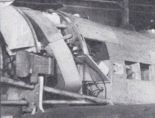
Hi Raiden!
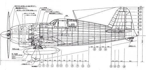
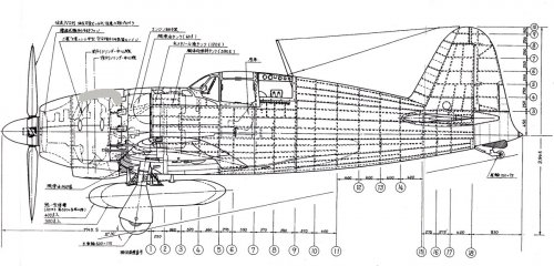
You can see ram air intake for supercharger behind of the forced cooling fan. Sorry for off topic.
Raiden also had an ADI system.
水メタノール液タンク 120L (Water methanol tank 120L)
Source : ISBN4-05-602378-6, Interceptor Raiden Gakken, 10/11/2000
You can see ram air intake for supercharger behind of the forced cooling fan. Sorry for off topic.
Raiden also had an ADI system.
水メタノール液タンク 120L (Water methanol tank 120L)
Source : ISBN4-05-602378-6, Interceptor Raiden Gakken, 10/11/2000
Attachments
blackkite
Don't laugh, don't cry, don't even curse, but.....
- Joined
- 31 May 2007
- Messages
- 8,820
- Reaction score
- 7,721
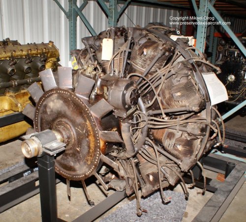
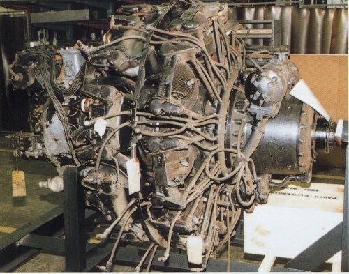
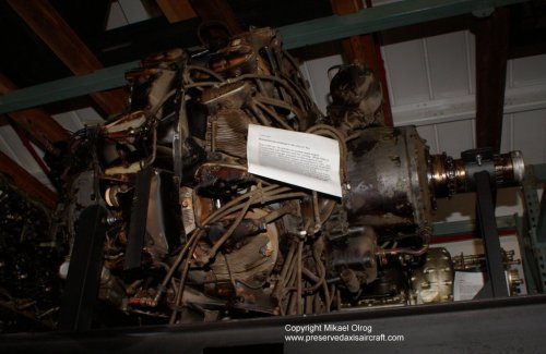
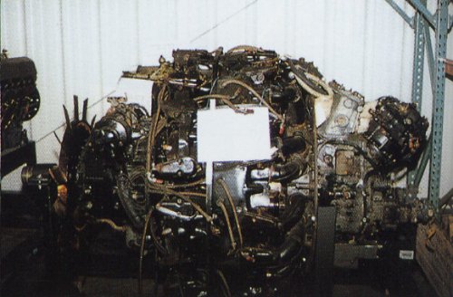
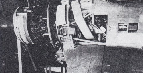
Perhaps I made a mistake. Ki-83's HA211-RU(HA-43-11 RU) engine did not have forced cooling fan.blackkite said:So Ki-83's engine had forced coolin fan.
I think that this engine is from Ki-83 which was tranported from Japan to the u.s. after the war and scrapped.
Reppu used this engine from Ki-83 removing turbocharger.
While HA-43-11 had forced cooling fan.
http://axis.classicwings.com/Japan/engines.htm
http://blogs.yahoo.co.jp/ponkotu1010/8864072.html
Attachments
Dear Blackkite,
A few questions if i may. I am always astonished (and grateful!) for the unique and fascinating images and info of japanese WW2 aircraft that you post. I am trying at the moment to get my head around J3K/J6K though, so i have a few queries:
1. J3K is the one with four cannon in the wing and two 13mm MGs at the wingroots, and intakes on the side of the engine cowling for the MK9A, right? So the 17 shi specification asked for two MGs and four cannons in the wings, and was issues in August 1942, but cancelled in early 1943. Does this mean that the mock-up must have been first built and inspected sometime in early 1943? We see a lot of drawings showing two MGs OVER the nose (like A6M Zero) and two cannons in the wing, is this accurate and is it related to J3K or J6K? In some articles i have read about either two 30mm cannons in the wings or four 20mm cannons. Any additional details about other requirements of 17-shi specification?
2. The J6K is an updated J3K to conform to the 18-shi specification, little different shape wise from J3K and is the one with NO intakes on the side of the NK9A-O engine, SIX 20mm cannons in the wings and two MGs at the wingroots, but because the mock-up shown in the pictures is the J3K one modified to represent J6K and photographed at different times, peoples got confused hence for instance the drawings of the J6K Jinpu with BOTH engine side air intakes AND six 20mm cannons in the wings. Am i close enough?
Many thanks!
PS: well, just to muddy things even further, i have just remembered that in the Ki-87 topic on the last page there is a drawing of a notional N1K6-J with a Ha-45-44 engine which has a two stage 3 speed supercharger, and it has two side intakes behind the engine like the MK9A powered J3K or N1K5-J! The NK9A-O aka Ha-45-42 of the J6K also has a 2 speed 3 stage supercharger, but this variant does not need side intakes behind the engine? Or perhaps the J6K also has side intakes behind the engine, just that it's not visible on the modified mock-up?
http://www.secretprojects.co.uk/forum/index.php/topic,9572.15.html
Thank you, looking forward to it!
Meanwhile, i have just posted this in the Shiden variants topic:
http://www.secretprojects.co.uk/forum/index.php/topic,3494.75.html
So related to that, since the J3K was supposed to have a MK9A engine, and since it appears this engine variant does not require side intakes, could it be that the Jinpu drawings that we see without those intakes, and sometime with two MGs over the nose (like A6M) and two cannons in the wings might actually represent the earlier J3K configuration?
blackkite
Don't laugh, don't cry, don't even curse, but.....
- Joined
- 31 May 2007
- Messages
- 8,820
- Reaction score
- 7,721
Hi!
http://www.secretprojects.co.uk/forum/index.php/topic,4802.45.html
17-shi land base high altitude fighter J3K had a Mitsubishi MK9B(HA-43-21) engine with vulkan coupling drive first stage supercharger and mechanical drive second stage supercharger same as Shinden MK9D engine. So J3K had engine side air intakes for vulkan coupling drive supercharger same as Shinden.
I imagine MK9B engine shape looks like MK9D engine. But MK9B engine was for tractor type propeller, vulkan coupling drivwe supercharger was located behind the engine. Shinden MK9D pusher propeller engine vulkan coupling supercharger was located front of the engine.
The IJN's requirement for J3K armament in 1942 was 20mm cannon×2 and 13mm gun×2.
blackkite
Don't laugh, don't cry, don't even curse, but.....
- Joined
- 31 May 2007
- Messages
- 8,820
- Reaction score
- 7,721
blackkite
Don't laugh, don't cry, don't even curse, but.....
- Joined
- 31 May 2007
- Messages
- 8,820
- Reaction score
- 7,721
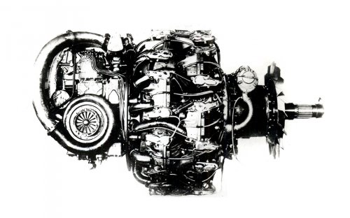
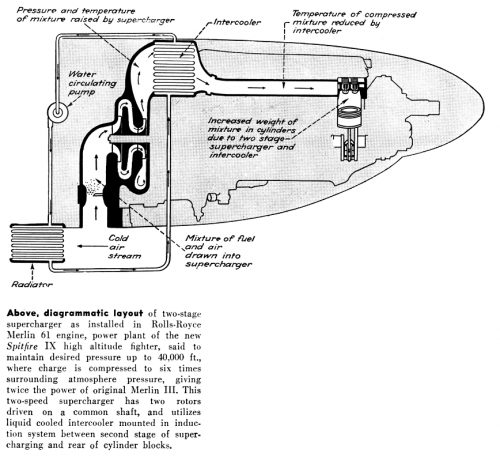
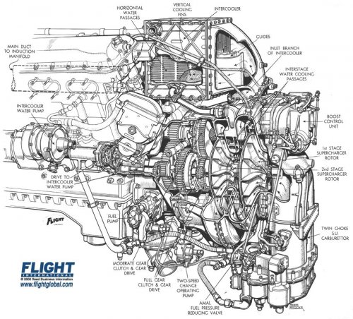
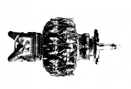
I imagine that NK9A-O engine 2 stage 2 speed mechanical supercharger shape looks like this picture(Rolls Royce Marine 61).
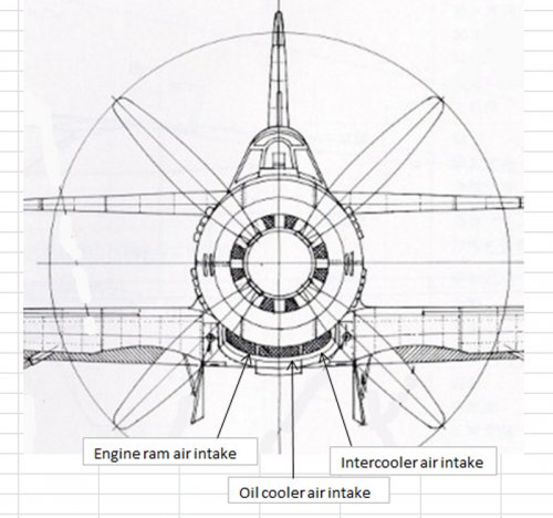
I imagine that J6K engine ram air intake to first stage super charger was located behind the forced cooling fan of the engine or bottom of the engine nacelle. So J6K engine did not need engine nacelle side air intake.
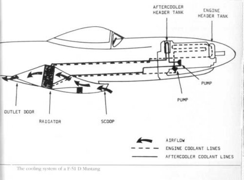
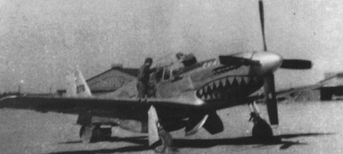
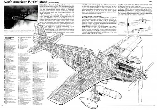
The IJA captured P-51C at China in February 1945.
P-51 engine ram air intake was located front bottom of the fuselage.
P-51 intercooler is cooled by liquid!!
But J6K engine intercooler was cooled by the air. J6K engine was Nakajima NK9A-O air cooled radial with two stage three speed mechanical supercharger and intercooler.
Front view of J6K by famous Minoru Matsubara.
http://www.secretprojects.co.uk/forum/index.php?action=dlattach;topic=4802.0;attach=529358;image
Side view of J6K by famous Minoru Matsubara.
http://www.secretprojects.co.uk/forum/index.php?action=dlattach;topic=4802.0;attach=529304;image
I imagine that J6K engine ram air intake to first stage super charger was located behind the forced cooling fan of the engine or bottom of the engine nacelle. So J6K engine did not need engine nacelle side air intake.
The IJA captured P-51C at China in February 1945.
P-51 engine ram air intake was located front bottom of the fuselage.
P-51 intercooler is cooled by liquid!!
But J6K engine intercooler was cooled by the air. J6K engine was Nakajima NK9A-O air cooled radial with two stage three speed mechanical supercharger and intercooler.
Front view of J6K by famous Minoru Matsubara.
http://www.secretprojects.co.uk/forum/index.php?action=dlattach;topic=4802.0;attach=529358;image
Side view of J6K by famous Minoru Matsubara.
http://www.secretprojects.co.uk/forum/index.php?action=dlattach;topic=4802.0;attach=529304;image
Attachments
blackkite
Don't laugh, don't cry, don't even curse, but.....
- Joined
- 31 May 2007
- Messages
- 8,820
- Reaction score
- 7,721
blackkite
Don't laugh, don't cry, don't even curse, but.....
- Joined
- 31 May 2007
- Messages
- 8,820
- Reaction score
- 7,721
Many thanks for your help Blackkite and fantastic materials, i had no idea that Jinpu factory drawings survived! If there are any more such materials would be great to see them! Is there info as to the speed requirement for J3K, is it still 685kph (370kts) like for J6K or less than that?
Well, it appears the N1K5-J engine could be a multistage MK9 which could be the B version (two stage, two speed right - vulkan coupling first stage, mechanical second stage), which would make sense as it was designed in a time when Japan was desperate for high altitude fighters, so this means that what we have read all these years in the few (in the english speaking world at least) works on japanese aircraft namely the N1K5-J has a MK9A engine, is not correct. In the factory drawing of the N1K5-J, it explicitly says the engine is a MK9?
As to the MK9, i have tried to find some info on the web but it's inconclusive at this point, i'm trying to find out when the engine was first run and when it was flown in a prototype of any type for first time. The program was started in 1941 i read, and it appears the first MK9/Ha-211 flew in the Ki-70 and Ki-74, any additional info and dates? It's either late 1943 or early 1944.
blackkite
Don't laugh, don't cry, don't even curse, but.....
- Joined
- 31 May 2007
- Messages
- 8,820
- Reaction score
- 7,721
1. Unfortunately I can't find J3K speed requirement in Japanese sources.
2. Almost all Japanese sources says that N1K5-J engine was Mitsubishi MK9A(Ha43-11) with single stage two speed machanical supercharger. (Maru magazine, Koku-fan famous aircraft of the world)
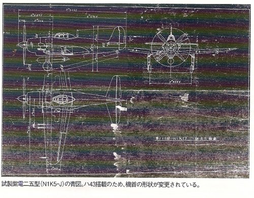
3. Mitsubishi A7M2 Reppu had a MK9A engine and engine ram air intake was located top of the engine nacelle. But I can't fine N1K5-J engine ram airintake at top of the engine nacelle. So air intake located side of the engine nacelle is ram air intake. But why split two intake?
MK9B engine vulkan coupling drive first stage supercharger was devided into two impellers.
2. Almost all Japanese sources says that N1K5-J engine was Mitsubishi MK9A(Ha43-11) with single stage two speed machanical supercharger. (Maru magazine, Koku-fan famous aircraft of the world)
3. Mitsubishi A7M2 Reppu had a MK9A engine and engine ram air intake was located top of the engine nacelle. But I can't fine N1K5-J engine ram airintake at top of the engine nacelle. So air intake located side of the engine nacelle is ram air intake. But why split two intake?
MK9B engine vulkan coupling drive first stage supercharger was devided into two impellers.
Attachments
blackkite
Don't laugh, don't cry, don't even curse, but.....
- Joined
- 31 May 2007
- Messages
- 8,820
- Reaction score
- 7,721
This picture shows MK9A engine. You can see one engine air intake duct to supercharger(which connected engine nacelle front end top ram airintake by duct) at rear end of the engine.(silver color parts)
So I think it's logical that N1K5-J had a MK9B engine.
So I think it's logical that N1K5-J had a MK9B engine.
Attachments
blackkite
Don't laugh, don't cry, don't even curse, but.....
- Joined
- 31 May 2007
- Messages
- 8,820
- Reaction score
- 7,721
A20A(MK9A) engine fablication was finished in middle of February 1942. The first run was started few days after finish of fablication.
Source : THE HISTORY OF MITSUBISHI AERO-ENGINES 1915-1945, MIKI PRESS, 10/9/2005, ISBN4-89522-461-9
Also this book says when the MK9 engine flown on an aircraft for first time was A7M2 in October 1944.
In 13/10/1944, A7M2 was ferried to Suzuka airport from Mitsubishi factory.
HmHm...Ejector exhaust!! This is the first time for me to hear this techinical term. Thansk a lot lancer 21-san.
In Japan we call this system as rocket nozzle or single exhaust thrust nozzle. ;D
Attachments
blackkite
Don't laugh, don't cry, don't even curse, but.....
- Joined
- 31 May 2007
- Messages
- 8,820
- Reaction score
- 7,721
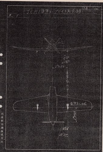
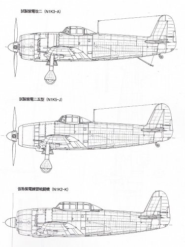
This midddle drawings shows famous Rikyu Watanabe's image for N1K5-J. Perhaps engine is MK9A.
I wonder where is engine ram air intake. Behind engine forced cooling fan same as Raiden and FW-190?
Source : FAMOUS AIRCRAFT OF THE WORLD, N0124, Kyufu, Shiden and Shiden-kai. ISBN978-4-89319-158-8
Following N1K5-J types were planned?
(1) MK9A engine type.
(2) MK9B engine type.
I wonder where is engine ram air intake. Behind engine forced cooling fan same as Raiden and FW-190?
Source : FAMOUS AIRCRAFT OF THE WORLD, N0124, Kyufu, Shiden and Shiden-kai. ISBN978-4-89319-158-8
Following N1K5-J types were planned?
(1) MK9A engine type.
(2) MK9B engine type.
Attachments
Again, many thanks for your invaluable input Blackkite. In the Mitsubishi book, does it says when the MK9 engine was flown on an aircraft for first time?
And as to the FAOTW N1K5-J drawing, strange that the engine deos not have ejector exhaust but a normal old-style collector. Reppu's MK9A engine for instnace (not to mention pretty much all japanese military aircarft of the day) had ejector exhausts.
And as to the FAOTW N1K5-J drawing, strange that the engine deos not have ejector exhaust but a normal old-style collector. Reppu's MK9A engine for instnace (not to mention pretty much all japanese military aircarft of the day) had ejector exhausts.
blackkite
Don't laugh, don't cry, don't even curse, but.....
- Joined
- 31 May 2007
- Messages
- 8,820
- Reaction score
- 7,721
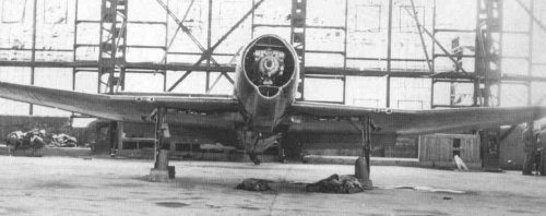
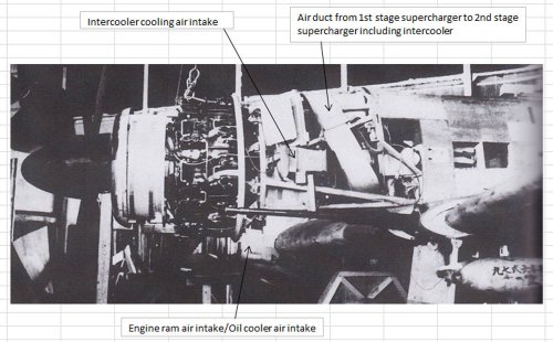
This picture is hard to understand for me.
Text box shows my poor opinion. My opinion need engine nacelle side air intake.Different from factory drawing.;D
I feel it's difficlut to have engine ram air intake or intercooler cooling air intake inside of the engine nacelle behind force cooling fan because engine nacelle is very slim.
Text box shows my poor opinion. My opinion need engine nacelle side air intake.Different from factory drawing.;D
I feel it's difficlut to have engine ram air intake or intercooler cooling air intake inside of the engine nacelle behind force cooling fan because engine nacelle is very slim.
Attachments
windswords
ACCESS: Secret
- Joined
- 19 May 2009
- Messages
- 389
- Reaction score
- 218
Hi Blackkite,
Thanks for posting the video. It looks like the author went to the Battlestar Galactica "Shaking" camera school of CGI animation. ;D
Thanks for posting the video. It looks like the author went to the Battlestar Galactica "Shaking" camera school of CGI animation. ;D
I too enjoyed the Jinpu video very much, thanks Blackkite. Hopefully some clearer CGIs will appear.
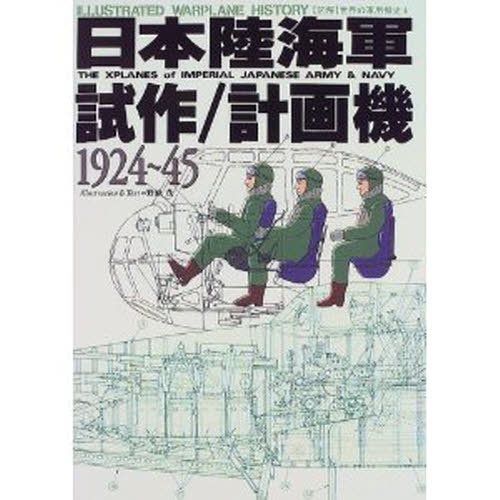
On another note, i have just realized that some of the the Jinpu drawings depicting it with side intakes actually show only ONE intake on the left, sort of like Bf-109. This image is from the book "The X planes of the Imperial Japanese Army/Navy 1924-1945", hope it's OK to post it here.
On another note, i have just realized that some of the the Jinpu drawings depicting it with side intakes actually show only ONE intake on the left, sort of like Bf-109. This image is from the book "The X planes of the Imperial Japanese Army/Navy 1924-1945", hope it's OK to post it here.
Attachments
blackkite
Don't laugh, don't cry, don't even curse, but.....
- Joined
- 31 May 2007
- Messages
- 8,820
- Reaction score
- 7,721
HmHm........Impressive!
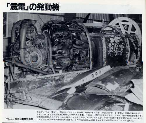
Japanese text of this picture say s that the engine is Nakajima Homare modified type 201?.
May be this picture shows J6K, but famous Minoru Matsuba shows us another drawing for J6K without engine nacelle side air intake.
I wonder what his base is.
Anyway it's true that we do not have precise and detailed J3K/J6K official drawings.
We only have some mockup pictures.
Following picrure shows Mitsubishi A18E engine plan view. You can see valkan coupling drive twin rotor first stage supercharger.
I think J3K's MK9B engine looks like this engine. So I think J3K had engine nacelle side air intake at the both side same as J7W Shinden.
A18E side view.
http://www.secretprojects.co.uk/forum/index.php?action=dlattach;topic=4802.0;attach=564785;image
Attachments
blackkite
Don't laugh, don't cry, don't even curse, but.....
- Joined
- 31 May 2007
- Messages
- 8,820
- Reaction score
- 7,721
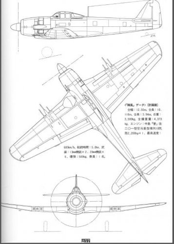
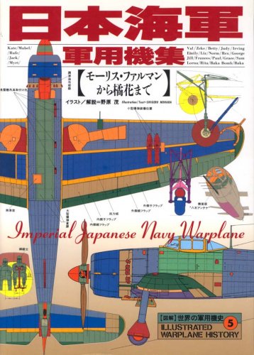
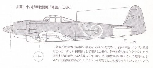
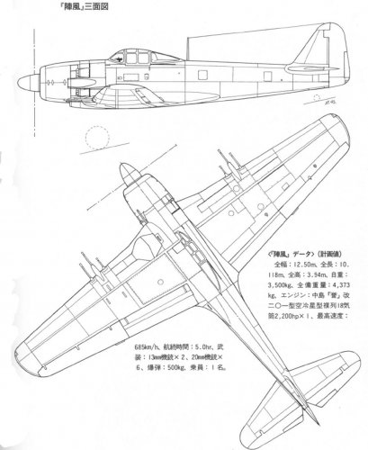
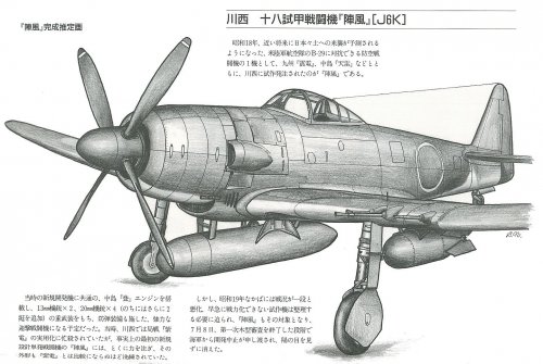
Top drawing shows J6K Jinpu by Japanese famous WW2 Japanese aircraft researcher Shigeru Nohara which appeared in his "THE XPLANES of IMPERIAL JAPANESE ARMY & NAVY" published in 1999. ISBN4-7663-3292-X,GREEN ARROW
Also bottom drawing shows J6K Jinpu by Shigeru Nohara which appeared in his "Imperial Japanese Navy Warplane" published in 1994.ISBN4-7663-3161-3,GREEN ARROW
In this book Shigeru Nohara said that Jinpu shape little changed from this drawing when mockup inspection by the IJN.
(木型審査時点では、イラストの形態とは少し異なるものになっていた。)
So Shigeru Nohara think that top drawing shows Jinpu final shape.
Source of top drawing : http://www.sas1946.com/main/index.php?topic=46694.0
Attachments
blackkite
Don't laugh, don't cry, don't even curse, but.....
- Joined
- 31 May 2007
- Messages
- 8,820
- Reaction score
- 7,721
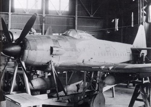
Hi! J6k1 Jinpu Larger images.
Top drawing is by Shigeru Nohara(野原 茂).
Nohara means "green feild."
Shigeru means "to grow thickly." ;D
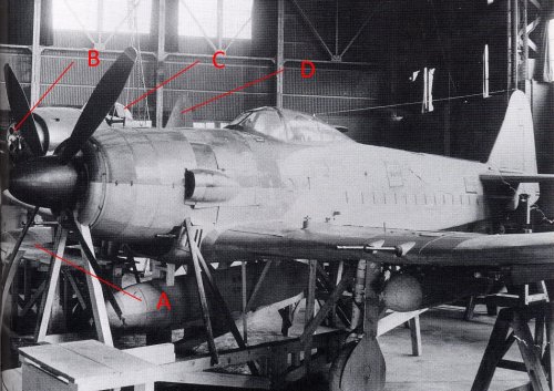
You can see another aircraft behind Jinpu mockup in bottom picture. J3K mockup?
Source of Jinpu images. : http://gefuv.bbfr.net/t7691p80-quizz-aviation
Top drawing is by Shigeru Nohara(野原 茂).
Nohara means "green feild."
Shigeru means "to grow thickly." ;D
You can see another aircraft behind Jinpu mockup in bottom picture. J3K mockup?
Source of Jinpu images. : http://gefuv.bbfr.net/t7691p80-quizz-aviation
Attachments
- Joined
- 1 May 2007
- Messages
- 2,596
- Reaction score
- 1,966
blackkite said:You can see another aircraft behind Jinpu mockup in bottom picture. J3K mockup? ;D
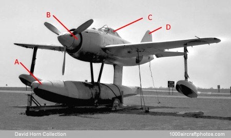
I think the other aircraft is a Kawanishi N1K Kyōfū. Compare the images below, source; http://1000aircraftphotos.com/Contributions/HornDavid/9091.jpg, post and above.
cheers,
Robin.
Attachments
blackkite
Don't laugh, don't cry, don't even curse, but.....
- Joined
- 31 May 2007
- Messages
- 8,820
- Reaction score
- 7,721
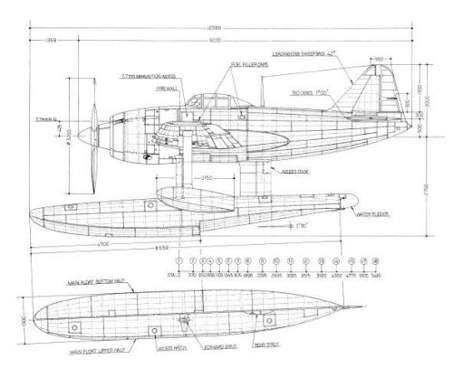
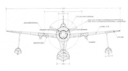
The IJN planned Shiden-kai seaplane fighter in October 1943.(Called Kyofu(強風, strong wind) type22)
Source : Super Zero fighter Reppu(烈風, gale), Maru, Kojinsha, 2/2/2011, ISBN978-4-7698-1490-0
Source : Super Zero fighter Reppu(烈風, gale), Maru, Kojinsha, 2/2/2011, ISBN978-4-7698-1490-0
Attachments
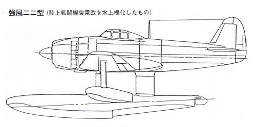
Fantastic stuff like always Blackkite-san, especially the Kyofu-22, that is completely new to me! They should have built the N1K1 like that in the first place (with a low wing)! At least they would have avoided the trouble with the telescopic landing gear, having to redesign the fuselage and so on. But hindsight is a wonderful thing.
blackkite
Don't laugh, don't cry, don't even curse, but.....
- Joined
- 31 May 2007
- Messages
- 8,820
- Reaction score
- 7,721
Jinpu J6K final planned engine was Nakajima Homare NK9K(A?)-O type 42 two stage two speed(three speed?) mechanical supercharged engine with intercooler, forced cooling fan and Oxygen injection.
NK9K(A?)-O enghine was a modified NK9A Homare type 41 engine.(two stage two speed(three speed?) mechanical supercharged engine with intercooler and forced cooling fan)
The reason why engine change from NK9A to NK9K(A?)-O was weight increase by two additional 20mm cannon.
Perhaps "-O" means Oxgen injection.
Source : Reppu and Reppu-kai, Gakken, ISBN4-05-602990-3, January/2004.
blackkite
Don't laugh, don't cry, don't even curse, but.....
- Joined
- 31 May 2007
- Messages
- 8,820
- Reaction score
- 7,721
From Japanese wikipedia,
Homare type 11 (Ha. 45-11, NK9B)
Homare initial production model.
4-shiki fighter Hayate initial production model engine was almost same as this model. Cooling fins were produced by the sand casting method instead of inserted fin type. Carburetor was type 115 hei B type. Position of injection of water methanol injection system was located just before the throttle (in the carburetor), different from later Homare type 21.
Homare type 12 (Ha. 45-12)
Changed Homare type 11 supercharger reduction ratio for performance improvement.
Water methanol injection location was moved over supercharger impeller.
This engine was applied to Ginga and Ryusei.
Homare type21 (Ha 45-21, NK9H)
Homare type 21 was a type 11 modification version. Increase the boost pressure and rpm, improving output to 200 hp. Carburetor was type 115 hei c .Water methanol injection system was changed to the method which methanol injected behind the impeller.This type cooling fins changed to inserted fin type.
This type was applied to Saiun, 4-shiki fighter Hayate, Shiden and Shiden-kai.
Homare type 22 (Ha 45-22, NK9K)
Changed type 21 propeller speed reduction ratio, equipped with forced cooling fan.
This type was applied to Saiun prototype and A7M1 Reppu.
Homare type 23 (Ha 45-23, NK9H-S)
type 21 with Nakajima type low pressure fuel injection system (not direct injection into the cylinder, to spray fuel into the intake manifold instead of carburetor )
This type was applied to Shiden type32(N1K4-J(experimental Shiden-kai 3)) and tested until the end of the war.
Homare type 24(Ha 45-24, NK9K-S)
Same as type 23, type 22 with low pressure fuel injection system.
Homare type 24-Lu(Ha. 45-24Lu, NK9K-L)
Type 24 with turbo charger. This type was applied to Saiun-kai and tested.
Homare type 25 (Ha. 45-25)
Corresponds to overload, improved crank shaft and tested until the end of the war.
Homare type 26 (Ha. 45-26)
Employed VDM type propeller reduction mechanism. Only prototype built.
Homare type 31(Ha 45-31, NK9K-O)
Modified type 21.
Added forced cooling fan, realize high revolution and high boost aimed to increase power (Take off power 2200 hp). Aborted in planning stage.
Homare type 41 (Ha. 45-41, NK9A)
Change supercharger type to 3-speed two-stage supercharger, added intercooler and forced cooling fan.
Only prototype built.
Homare type 42 (Ha. 45-42, NK9A-O).J6K.
Power improved type 41. (Take off power 2200 hp). Only prototype built.
Homare type 44-(Ha 45-44)
Type 41 without intercooler.(Take off power 1810 hp). Tested until the end of the war.
Planned to apply high performance Shiden-kai(temporary name)
Homare type 52 (Ha. 45-52, NK9L)
Type with turbocharger, fuel direct injection system and forced cooling fan.
Homare type 61(Ha 45-61, NK9M)
For pusher type aircraft equipped with shaft extension and forced cooling fan.
Shiden type32(N1K4-J(experimental Shiden-kai 3))
http://www.secretprojects.co.uk/forum/index.php?action=dlattach;topic=3494.0;attach=202643;image
CherryBlossom
English Literature with Film Studies student
- Joined
- 17 April 2014
- Messages
- 78
- Reaction score
- 5
Hello everyone,
It was discussed some time before on this topic, but was wondering if anyone found out more about the Kawanshi A8K1 Toppu?
It seems that there was speculation on whether this was indeed a real project and/if it was a carrier-based J6K.
Does anyone have any information or resources to prove its existence and what it was?
Thanks
Cherry
blackkite
Don't laugh, don't cry, don't even curse, but.....
- Joined
- 31 May 2007
- Messages
- 8,820
- Reaction score
- 7,721
Oh Toppu(突風)!! This is the first time for me to see this name.
突風 means
•a (sudden) gust of wind
or
•a squall
or
•a blast of wind
I find this site.
https://forum.valka.cz/category/view/500610/Kawanisi
突風 means
•a (sudden) gust of wind
or
•a squall
or
•a blast of wind
I find this site.
https://forum.valka.cz/category/view/500610/Kawanisi
Similar threads
-
 IJN Specification 12-Shi (E12/E13, Reconnaissance Seaplane, 1937)
- Started by blackkite
- Replies: 25
-
-
-
 other less known japanese aircraft projects
- Started by airman
- Replies: 14
-
 Nakajima Ki-201 Karyu and "J9N/J9Y" Kikka
- Started by Michel Van
- Replies: 141