Hi Blackkite san
very rare and beatiful photos of the mockup of the Jinpu!,especially the cockpit pic is very awsome I must say!
thanks for sharing these photos!
By the wa I was wondering what aircraft cannon means in Japanese
 
Bringing up an old thread, what did the A8M you mentioned look like, a link in another thread http://www.geocities.co.jp/Colosseum/2610/twinzero.html does not load the image.
hesham said:
Hi,

also the Mitsubishi A8M Rikufu for 20-Shi competition.
 
Winston said:
Bringing up an old thread, what did the A8M you mentioned look like

Here is the only image I have of a "20-shi" Mitsubishi fighter.
 

Attachments

  • 20-shi Ko fghter Mitsubishi 16_6m span wing.jpg
    20-shi Ko fghter Mitsubishi 16_6m span wing.jpg
    549.7 KB · Views: 501
The website says twin-boom, but I'm guessing that is just a made up design?
 
Terribly sorry. I made a big mistake. Perhaps this picture shows J3K1 with Mitsubishi MK9B engine.
Engine nacelle side air intake is for Vulcan coupling drive first stage supercharger.
Upper picture was taken in 8/7/1944 before the second mockup inspection by the IJN. Bottom picture was taken in 2/6/1944 before the first mockup inspection by the IJN. Engine part is little different between two pictures. Some modification was applied to the mockup model after the first inspection.

I imagine that Kawanishi received the first inspection for J6K1 using J3K1 mockup.
 

Attachments

  • J3K1 mock up.jpg
    J3K1 mock up.jpg
    1.1 MB · Views: 322
  • MOCKUP PIC1.jpg
    MOCKUP PIC1.jpg
    377.4 KB · Views: 223
  • MOCKUP PIC3.jpg
    MOCKUP PIC3.jpg
    361.7 KB · Views: 237
This is J6K1 with Nakajima NK9A-O non turbo charged two stage three speed mechanical super charged engine.NK9A-O had a intercooler.
Kawanishi received the first full scale mockup inspection by the IJN in 2/6/1944, and planned to received the second inspection in July 1944. But J6K1 project was cancelled in 8/7/1944 before the second mockup inspection.
 

Attachments

  • J6K with nonturbo charged NK9A-O engine.jpg
    J6K with nonturbo charged NK9A-O engine.jpg
    25 KB · Views: 307
Hi! J3K1.
 

Attachments

  • J3K1.jpg
    J3K1.jpg
    104.4 KB · Views: 292
awsome stuff again as usually Blackkite san! one thing is conspicuous to me one version has a straight wing the other has inverted gull wing like Reppu and corsairfighters
 
T-50 said:
awsome stuff again as usually Blackkite san! one thing is conspicuous to me one version has a straight wing the other has inverted gull wing like Reppu and corsairfighters

Hi! Good point.
I feel both J3K1 and J6K1 had inverted gull wing. But the number of cannon of the wing was changed.
I will check other Japanese sources.
 

Attachments

  • 820526d349f14ad9621ef63544245138.jpg
    820526d349f14ad9621ef63544245138.jpg
    49.1 KB · Views: 237
  • Jinpu.png
    Jinpu.png
    309.8 KB · Views: 255
  • 8566_3.jpg
    8566_3.jpg
    91.1 KB · Views: 206
  • 8566_2.jpg
    8566_2.jpg
    73.4 KB · Views: 250
  • J6K1  3-drawing-ww2shots-air force.jpg
    J6K1 3-drawing-ww2shots-air force.jpg
    682.8 KB · Views: 622
  • J6K1_3D_view.gif
    J6K1_3D_view.gif
    39.3 KB · Views: 582
  • jinpu.jpg
    jinpu.jpg
    20.8 KB · Views: 544
  • J3K1 MOCKUP.jpg
    J3K1 MOCKUP.jpg
    249.7 KB · Views: 551
  • MOCKUP PIC1.jpg
    MOCKUP PIC1.jpg
    377.4 KB · Views: 602
Hi! Jinpu control panel.

Japanese explanation of this site says that....

An unclear meter has more than one vertical line and 1 horizontal line.
An unclear meter seems indicator unit of a radar (cathode-ray tube), but there is no such mentioning in every material.
I can think an unclear meter is a radar display. FK-3 radio cautious machine has been complete in June, 1945 in Kawanishi.
The weight is serious little with 60Kg.
I'm thinking there is a possibility that only indicator unit of FK-3 radio cautious machine was installed in the mock up enough at the time of the 1st time mock up examination held in June, 1944.

http://gunsight.jp/c/jinpu-3D.htm
1 Ignition Switch
2 Indicator (FK-3 radar)
3 Zero-shiki compass type 2
4 Oxyge flow meter type 2
5 Pressure gauge (detail obscurity)
6 Landing gear position indicator
7 Fuel gauge
8 1-Go exhaust gas thermometer
9 Rev counter type 1
10 Turn indicator
11 Speed indicator type 3 modification 2
12 Clock (the latter period type)
13 Fuel selection lever
14 1-Go cylinder Head Temperature Gauge
15 1-Go manifold air pressure gauge type 3
16 Gyro horizons type 2
17 Sensitive altimeter type 3
18 Passage meter
19 Inclinometer type 2
20 Power supply
21 Fuel gauge
22 2-Go oil pressure gauge type 4 (methanol)
23 15-shi Defi Racer Gauge
24 Ku-1-shiki romote indication compass type 3?
25 Degrees of ascent and descent type 2
26 Supply air thermometer
a Unclear knob
b Unclear lever
c Unclear lever
d Hand pump (detail obscurity).
 

Attachments

  • Jinpu_control_panel.png
    Jinpu_control_panel.png
    428.1 KB · Views: 173
I think that this drawing shows Jinpu mockup correctly.
But we can not see engine nacelle side air intake in plan view drawing.
Perhaps the engine in side view drawing shows Mitsubishi MK9B for J3K1.
The armaments in wing shows six 20mm cannon for J6K1.
Side view drawing shows J3K1 except armaments and plan view drawing shows J6K1. ;D
We can see inverted gull wing shapr in a little while in side view drawing.

The planar shape of Jinpu is little similar to FW190. Jinpu Planar shape is quite more dauntless than Reppu.

J3K1 (Kawanishi 17-shi land base fighter, J3K1 (KX-2) :
Kawanishi had a plan for land base fighter called K90 with Nakajima Homare engine.
Kawanishi wanted to develop this plan as J3K1.
But the IJN ordered Kawanishi to install Mitsubishi MK9B engine to J3K1.
Kawanishi began to develop this fighter in August 1942.
J3K1 development was terminated due to MK9B engine Vulkan coupling trouble in beginning of 1943.
J6K1 (Kawanishi 18-shi Ko-fighter, Jinpu(陣風)) :
In 1/8/1943, the IJN ordered Kawanishi to develop J6K1 with Nakajima Homare 42 engine (NK9A-O, 2 stage 3 speed mechanical supercharged engine).
Kawanishi received the first mockup inspection by the IJN in 2/6/1944.
J6K1 was cancelled in 8/7/1944 just before the second mockup inspection by the IJN.
In May 1945, the IJN considered next fighter plan based on J6K1, but never realized.
 

Attachments

  • Jinpu.png
    Jinpu.png
    309.8 KB · Views: 230
Correct side view drawing for J6K1 is this one by famous Minoru Matsuba,

This J3K1/J6K1 Jinpu project was the pitiful project twisted severely by the INJ and MK9B engine same as Reppu.
 

Attachments

  • J6K with nonturbo charged NK9A-O engine.jpg
    J6K with nonturbo charged NK9A-O engine.jpg
    25 KB · Views: 197
Hi FK-3 Radar!
http://www91.odn.ne.jp/yaswara/antennan/yu-gun.html
 

Attachments

  • Jinpu mockup control panel picture.jpg
    Jinpu mockup control panel picture.jpg
    8.3 KB · Views: 821
  • fk-3.gif
    fk-3.gif
    34.9 KB · Views: 147
Hi! Jinpu mockup pictures.
Source : Maru magazine 7/1993
 

Attachments

  • wing and cannon 2.jpg
    wing and cannon 2.jpg
    203.6 KB · Views: 144
  • Wing and 20mm cannon.jpg
    Wing and 20mm cannon.jpg
    1 MB · Views: 119
  • Wing.jpg
    Wing.jpg
    421.4 KB · Views: 122
  • Fuselage structure.jpg
    Fuselage structure.jpg
    293.7 KB · Views: 121
  • Gun camera on the wing.jpg
    Gun camera on the wing.jpg
    354.1 KB · Views: 116
  • Tail stabilizer.jpg
    Tail stabilizer.jpg
    182.1 KB · Views: 108
  • Wing fillet.jpg
    Wing fillet.jpg
    781.7 KB · Views: 102
  • Jinpu mockup pic3.jpg
    Jinpu mockup pic3.jpg
    406.6 KB · Views: 112
  • Jinpu mockup pic2.jpg
    Jinpu mockup pic2.jpg
    409.2 KB · Views: 122
  • Jinpu mockup pic1.jpg
    Jinpu mockup pic1.jpg
    561.5 KB · Views: 132
Hi!
 

Attachments

  • Control panel.jpg
    Control panel.jpg
    453.1 KB · Views: 135
  • Cockpit left and right side.jpg
    Cockpit left and right side.jpg
    928 KB · Views: 112
  • Cockpit.jpg
    Cockpit.jpg
    1 MB · Views: 106
  • Landing gear.jpg
    Landing gear.jpg
    762.7 KB · Views: 113
Hi!
Source :日本軍試作機, The IJA and the IJN experimental aircraft, ISBN4-575-47587-4
You can see oil cooler/inter cooler air intake at the bottom of the engine nacelle.
 

Attachments

  • Tail.jpg
    Tail.jpg
    560.2 KB · Views: 140
  • Jinpu engine.jpg
    Jinpu engine.jpg
    850 KB · Views: 143
  • 51+ieUVjicL.jpg
    51+ieUVjicL.jpg
    45.5 KB · Views: 172
  • Jinpu side view.jpg
    Jinpu side view.jpg
    292.8 KB · Views: 218
  • Jinpu plan view and front view.jpg
    Jinpu plan view and front view.jpg
    958.8 KB · Views: 264
Hi Blackkite san my compliments of all marvelous pictures and data! I enjoyed every picture of the mock up of the Jinpu.
This fighter was an ideal answer to the Grumman F8F Bearcat,I think even better than the F8F!
 
T-50 said:
Hi Blackkite san my compliments of all marvelous pictures and data! I enjoyed every picture of the mock up of the Jinpu.
This fighter was an ideal answer to the Grumman F8F Bearcat,I think even better than the F8F!
Hi T-50 san. Thanks for your appliciation.
Same source
 

Attachments

  • same scale side view 1.jpg
    same scale side view 1.jpg
    402.8 KB · Views: 383
  • same scale 2.jpg
    same scale 2.jpg
    714.1 KB · Views: 378
Amazing poster. Thanks for sharing!

I noticed a small typo though: "Pasty" should read "Patsy"! (a pasty is a sort of pie in England... Patsy is short for Patricia)

Any idea why the Ki-93 is attributed to "Koukukoushou" (never heard of this) instead of Rikugun? Thanks for your answer.
 
Hi!
Tachikawa Army Aero Arsenal ; 立川 陸軍 航空 工廠(Tachikawa Rikugun Koku Kosho)
Rikugun(陸軍) means the IJA. Riku(陸) means the land, Gun(軍) mean the army, Koku(航空) means Aero, Kosho(工廠) means the Arsenal.

Ki-74 is Patsy(Patricia).

The second picture left side runway is Yokota Air base.
http://www.airliftmagazine.com/friendship-festival/#schedule
 

Attachments

  • 立川陸軍航空工廠跡_三本煙&#3.jpg
    立川陸軍航空工廠跡_三本煙&#3.jpg
    273.9 KB · Views: 162
  • Tatikawa_AB_ato1.jpg
    Tatikawa_AB_ato1.jpg
    468.6 KB · Views: 144
  • F1000275.jpg
    F1000275.jpg
    338.2 KB · Views: 142
  • Tokyo and Yokota base upper left.jpg
    Tokyo and Yokota base upper left.jpg
    564.3 KB · Views: 146
  • Yokota air base.jpg
    Yokota air base.jpg
    747.9 KB · Views: 182
blackkite said:
T-50 said:
Hi Blackkite san my compliments of all marvelous pictures and data! I enjoyed every picture of the mock up of the Jinpu.
This fighter was an ideal answer to the Grumman F8F Bearcat,I think even better than the F8F!
Hi T-50 san. Thanks for your application.
Same source
wow these pics are also very cool thanks for sharing these Blackkite san!
 
Through Jinpu topic, I realize that if aircooling engine had a forced cooling fan, there was no air intake for supercharger at the front top of the engine nacelle. Perhaps air intake for supercharger was located behind the forced cooloing fan.
Reppu and Shiden-kai had a air intake for supercharger at the front top of the engine nacelle, because their engine did not have a forced cooling fan.
Reppu prototype had a forced cooling fan.
It's that I should be surprised, but there even are no air intakes for an oil cooler at outside of the engine nacelle in case of Aichi Denko fighter.
 

Attachments

  • Raiden engine supercharger air intake 4.jpg
    Raiden engine supercharger air intake 4.jpg
    237.4 KB · Views: 129
  • Raide engine supercharger air intake 3.jpg
    Raide engine supercharger air intake 3.jpg
    256.9 KB · Views: 113
  • Raide engine supercharger air intake 2.jpg
    Raide engine supercharger air intake 2.jpg
    93.8 KB · Views: 106
  • Raiden engine supercharger air intake 1.jpg
    Raiden engine supercharger air intake 1.jpg
    136.1 KB · Views: 149
  • Denko.jpg
    Denko.jpg
    46.5 KB · Views: 540
  • Raiden.jpg
    Raiden.jpg
    50.2 KB · Views: 579
  • A7M-tigai.jpg
    A7M-tigai.jpg
    39.2 KB · Views: 573
  • Reppu.jpg
    Reppu.jpg
    38.5 KB · Views: 581
  • Shiden-kai.jpg
    Shiden-kai.jpg
    68.1 KB · Views: 601
Hi! Denko engine nacelle.
Denko's air intake for supercharger and air intake for oil cooler were located behind forced cooling fan.

油冷却器 : Oil cooler.
 

Attachments

  • Denko engine nacelle 2.jpg
    Denko engine nacelle 2.jpg
    265.7 KB · Views: 193
  • Denko engine nacelle.jpg
    Denko engine nacelle.jpg
    262.1 KB · Views: 175
So Ki-83's engine had forced coolin fan.
 

Attachments

  • KI-83 front view.jpg
    KI-83 front view.jpg
    162.2 KB · Views: 153
Hi! In case of FW190.
 

Attachments

  • lrg0164.jpg
    lrg0164.jpg
    29.7 KB · Views: 122
  • BMW801.jpg
    BMW801.jpg
    220.9 KB · Views: 130
  • AP_G_4303_FW190-aircool_p054_W.png
    AP_G_4303_FW190-aircool_p054_W.png
    59.1 KB · Views: 141
  • FW190.jpg
    FW190.jpg
    113.3 KB · Views: 139
Grumman F8F Bearcat did not have a forced cooling fan in it's engine. Ram air intake for supercharger were located at the wing root(No.141).
R-2800 was very powerfull. It's not necessary to have a forced cooling fan.
 

Attachments

  • 02-Grumman-F8F-1-Bearcat.jpg
    02-Grumman-F8F-1-Bearcat.jpg
    1.2 MB · Views: 192
blackkite said:
Grumman F8F Bearcat did not have a forced cooling fan in it's engine. ... R-2800 was very powerfull. It's not necessary to have a forced cooling fan.
I think that the necessity probably depends on the engine, the installation, the operating conditions, and the available fuel. When all factors are taken into account, I suspect that forced cooling seems absolutely necessary in the cases in which it was adopted.

The F8F was a late design. By that point, Pratt-and-Whitney had more experience than anyone with air-cooled engines, close-finning, baffling, and cowling design. The R-2800 was mature and highly developed. P&W worked closely with the airframe designers, so the Grumman cowling was probably close to optimal for the engine and application.

US engine and airframe designers also had the advantage of lots of very high-octane, 115/145 fuel--something that often gets left out of these discussions. High octane inhibits detonation, so the engine can run at higher temperatures with less risk. Air-cooled engines are internally cooled, in part, by the evaporation of the fuel. So having the luxury of rich mixtures meant less need for more mechanically involved cooling solutions.
 
iverson said:
blackkite said:
Grumman F8F Bearcat did not have a forced cooling fan in it's engine. ... R-2800 was very powerfull. It's not necessary to have a forced cooling fan.
I think that the necessity probably depends on the engine, the installation, the operating conditions, and the available fuel. When all factors are taken into account, I suspect that forced cooling seems absolutely necessary in the cases in which it was adopted.

The F8F was a late design. By that point, Pratt-and-Whitney had more experience than anyone with air-cooled engines, close-finning, baffling, and cowling design. The R-2800 was mature and highly developed. P&W worked closely with the airframe designers, so the Grumman cowling was probably close to optimal for the engine and application.

US engine and airframe designers also had the advantage of lots of very high-octane, 115/145 fuel--something that often gets left out of these discussions. High octane inhibits detonation, so the engine can run at higher temperatures with less risk. Air-cooled engines are internally cooled, in part, by the evaporation of the fuel. So having the luxury of rich mixtures meant less need for more mechanically involved cooling solutions.
Hmmm....... ::)
I used to read that R-2800 marked 3,800hp at ADI's test stand and P-47's R-2800 marked 3,200hp at combat condition in some Japanese document.
What is ADI?
 
All I want to say through this discussion is that "If you can't find air intake for supercharger in J6K drawing, don't worry, air intake for supercharger is located behind forced cooling fan in engine nacelle".
You only see air intake for oil cooler(middle one) and inter cooler( both side one) bottom of the engine nacelle. ;D
 

Attachments

  • J6K with nonturbo charged NK9A-O engine.jpg
    J6K with nonturbo charged NK9A-O engine.jpg
    25 KB · Views: 172
  • Jinpu plan view and front view.jpg
    Jinpu plan view and front view.jpg
    958.8 KB · Views: 173
Hi Jinpu front view drawing,
 

Attachments

  • JAPANESE ARMY AND NAVY EXPERIMENTAL AIRCRAFT DESIGN WITH PRECISION.jpg
    JAPANESE ARMY AND NAVY EXPERIMENTAL AIRCRAFT DESIGN WITH PRECISION.jpg
    35.6 KB · Views: 203
  • Jinpu front view.jpg
    Jinpu front view.jpg
    138.9 KB · Views: 252
Some things I observe from Blackkites front view profile:

  • The landing gear has a wide track, good for rough fields, even carrier landings (I know this was a land based fighter but I could see a conversion possibility).
  • The outer half of the wings have a dihedral of 7 degrees, much like the A7M Repu.
  • Provision to carry 2 60 Kg bombs or 1 250 Kg bomb per wing.
  • A very small opening for cooling air for the radial engine.
Now some questions:

  • Could the designers have dropped the cooling fan if the propeller spinner was much small (think P-47 or F4U)?
  • Was it designed to carry drop tanks?
  • Could smaller guns (12.7mm) have been installed in the upper cowling, or was there not enough room?
 
Oh good point.
I will try to answer your question.
Hmmm.........spinner design. :-[
Perhaps Japanese designer want to use forced cooling fan in case of such a small propeller spinner like P-47, F4U and B-29.
Perhaps they try to design more small air intake area to realize more small drag.
 

Attachments

  • plan001.jpg
    plan001.jpg
    122.1 KB · Views: 206
"Perhaps they try to design more small air intake area to realize more small drag".

I see your point. Reduction of drag may have been the ultimate goal necessitating the use of a cooling fan.
 
Yes Japanese aero engine's power were very poor at the day.(Recent HONDA F1 turbo engine power is very poor,too. ;D)
Japanese designer forced to design aerodynamically clean aircraft to fulfill the IJA and the IJN's very hard requirements under poor engine power.)
 
•Could smaller guns (12.7mm) have been installed in the upper cowling, or was there not enough room?

Perhaps no room. You can see 13mm guns (三式13ミリ機銃)at the wing root.
 

Attachments

  • 三式13_2mm機銃.jpg
    三式13_2mm機銃.jpg
    155.3 KB · Views: 351
  • The IJN gun and cannon for the aircraft.jpg
    The IJN gun and cannon for the aircraft.jpg
    185.2 KB · Views: 357
  • The IJN large canno for the aircraft.jpg
    The IJN large canno for the aircraft.jpg
    85.4 KB · Views: 333
  • The IJA gun and cannon for the aircraft.jpg
    The IJA gun and cannon for the aircraft.jpg
    168.7 KB · Views: 312
  • The IJA lrage canno for the aircraft.jpg
    The IJA lrage canno for the aircraft.jpg
    194 KB · Views: 328
My apologies at asking about 12.7 mm guns, I forgot the navy used the 13.2 mm size.
 
Hi!
Source : Mr.Minoru Matsuba's book as usual.
 

Attachments

  • Jinpu side view.jpg
    Jinpu side view.jpg
    161.8 KB · Views: 640
  • JAPANESE ARMY AND NAVY EXPERIMENTAL AIRCRAFT DESIGN WITH PRECISION.jpg
    JAPANESE ARMY AND NAVY EXPERIMENTAL AIRCRAFT DESIGN WITH PRECISION.jpg
    35.6 KB · Views: 645
Hmmm....... ::)
I used to read that R-2800 marked 3,800hp at ADI's test stand and P-47's R-2800 marked 3,200hp at combat condition in some Japanese document.
What is ADI?
[/quote]

"ADI" is "Anti-Detonant Injection". Water spray was used to cool the intake charge so that the engine could run at higher supercharger boost pressures--and thus higher power--for short periods without causing disastrous detonation. American engines mainly used it for take-off with heavy loads. But I imagine it might also be used for short bursts of power during combat, such as when chasing a kamikazi at low altitude.

3800 hp with ADI (a LOT of ADI) on the test stand might be possible, but hardly practical in combat. The engine would probably need a rebuild after a relatively short running time. I seem to remember reading that a Napier Sabre made over 5000 hp under similar conditions.

More realistically, early R-2800 engines were rated at 1800 hp at 2600 rpm. When this was raised to 2000 hp at 2700 rpm, the original cast heads developed cooling issues, because the cast-in cooling fins were too few and too thick. C-series engines were therefore redesigned to use a forged head with more closely spaced, gang-sawed cooloing fins. Components were strengthened overall (stronger connecting rods, more teeth on the reduction gears, larger propeller shaft splines, etc.). With additional improvements to the supercharger and injection carburetor, power eventually went up to 2500 hp at 2800rpm or 2800 hp at the same rpm with ADI.

In the F8F-2, the R-2800-30W produced 2250 hp at 2800 rpm. My sources ("Allied Piston Engines of World War II" by Graham White and "Engines of Pratt and Whitney" by Jack Connors) list maximum power for the P-47N at 2100 hp at 2800 rpm and 35,000 ft. The altitude matters, because the P-47 engine was turbocharged and thus achieved maximum boost at maximum rated altitude. Turbocharging heated the compressed intake air more than mechanical supercharging, and the air was thinner to start with at altitude. This probably explains the lower power rating compared to a mechanically supercharged F8F engine running at sea level. American turbocharged engines had problems with overheating throught the war.

Remember too that the above are all short-duration, maximum-rpm, maximum-boost power ratings. In normal use, the F8F's R-2800-30W produced 1720 hp at 2600 rpm, while the P-47N's R-2800-73 produced 1700 hp at the same rpm.

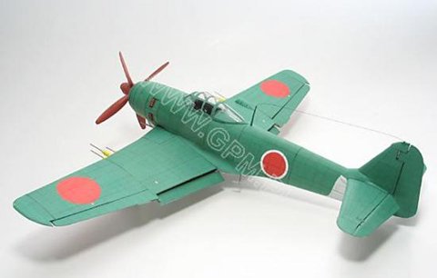
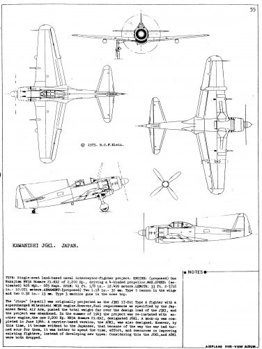
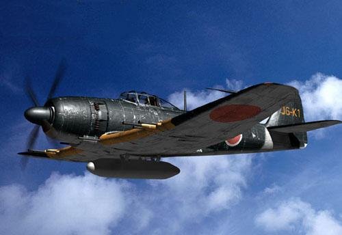
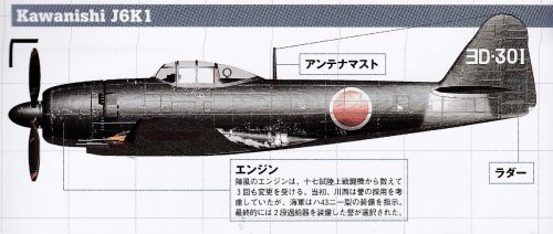
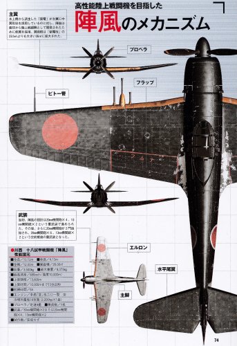
If we go back to the Japanese cooling fan question, I based my repliy on considerations like the above and on experience with how engineers think. Grumman and Kawanishi engineers faced entirely different sets of design constraints. So they came up with different solutions.

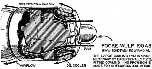
The R-2800 was the product of enormous technical and manufacturing resources that were not available in Japan. Grumman and P&W could base their design decisions on an abundance of high-quality fuel, raw material, and machine tools. High-octane fuel let the R-2800 run hotter without detonation. Surplus fuel let the engine use more of it. The close-finning made possible by sophisticated machine tools and a surplus of raw material maximized heat rejection. Long experience with airline operations led to baffling and cowling designs that optimized internal airflow while minimimizing cooling drag. So the F8F's engine did not need a fan. A fan would, if anything, have been an unneeded source of complexity, added weight, and consequent mantenance problems.

Japan's late-war aircraft and engine designs were the product of scarcity, lack of industrial capacity, lack of raw materials. So I expect that the difference between Kawanishi's J6K and the F8F reflects this fact. The Japanaese engineers could not adopt F8F- and R-2800-style design solutions because their starting point was different. They didn't have the time or resources to duplicate the trial-and-error experimentation that made P&W expert at low-drag air cooling. They couldn't keep supercharged engines cool using lots of high-octane fuel. So they adopted a solution that they could make work, the forced air cooling fan.
 
I receive very valuable information, and thank you very much.

You teach us that American turbocharged engines had problems with overheating throught the war.

I have the memory read by some book in the past that, “cooling performance is insufficient for an air-cooled engine at high altitude because heat transfer area(cooling fin total area) is limited”. I think an air-cooled engine for high altitude of turbo charging (and multistage mechanically supercharging) may be a little unreasonable theoretically. I'm thinking it's a forced cooling fan to settle that. Cooling air is fast by a forced cooling fan, and cooling performance may improve.
 
Back
Top Bottom