Here is an interesting overlay - my digitization of the Ju 87 airfoil from the Russian document, overlaid on a Ju 52 airfoil that I found measurements for in
https://www.fzt.haw-hamburg.de/pers/Scholz/arbeiten/AufgabeTaschner.pdfBTW, this thesis contains an error - the Ju 52 flap is normally 2.5 deg nose down, not 0 deg.

Yellow is Ju 52, magenta is Ju 87. The coordinates are on a unit chord, to allow an overlay. As you can see, the airfoils are related, but not the same.
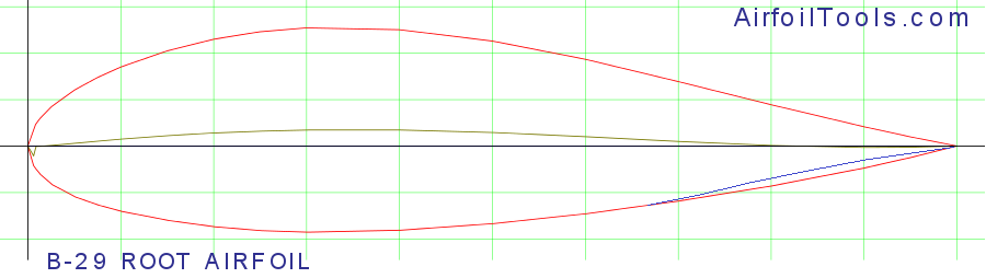
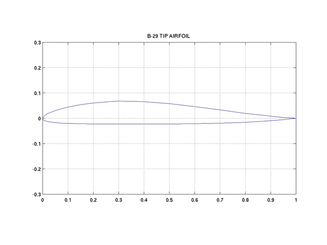
If I may add that this information can only be partial because I suppose it is the root profile, apart from the thickness of the profile which varies up to the salmon of the wing, its coordinates change most of the time. Ex. B-29 extreme wing airfoils ...Camber is crucial and can be scalable !..
 

Attachments

  • b29root-il_l.png
    b29root-il_l.png
    21.3 KB · Views: 151
  • b29tip.gif
    b29tip.gif
    11.2 KB · Views: 104
Hi Tonton,

If I may add that this information can only be partial because I suppose it is the root profile, apart from the thickness of the profile which varies up to the salmon of the wing, its coordinates change most of the time. Ex. B-29 extreme wing airfoils ...Camber is crucial and can be scalable !..

I suppose the tip airfoil is also shown on the Russian diagram ... the caption is illegible, but you can see the washout consistent with the separate washout diagram. (Now that I think about it, one could probably calibrate the aspect ratio of the perspective-corrected diagram with that information.)

What is "salmon of the wing", by the way? I read this as "tip airfoil", but that was only a guess! :)

Regards,

Henning (HoHun)
 
Hi Tonton,

If I may add that this information can only be partial because I suppose it is the root profile, apart from the thickness of the profile which varies up to the salmon of the wing, its coordinates change most of the time. Ex. B-29 extreme wing airfoils ...Camber is crucial and can be scalable !..

I suppose the tip airfoil is also shown on the Russian diagram ... the caption is illegible, but you can see the washout consistent with the separate washout diagram. (Now that I think about it, one could probably calibrate the aspect ratio of the perspective-corrected diagram with that information.)

What is "salmon of the wing", by the way? I read this as "tip airfoil", but that was only a guess! :)

Regards,

Henning (HoHun)
1688554286755.png
Dear Henning,

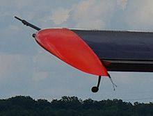
The "salmon" is red on this MH-152 Broussard. I used Reverso for translation but it wasn't a good idea !

Un petit dessin vaut mieux qu'un long discours ... (Napoléon) ;)

Tonton
 

Attachments

  • 149341756_1821451341340561_3961667098502900695_n.jpg
    149341756_1821451341340561_3961667098502900695_n.jpg
    16.2 KB · Views: 92
  • 149171530_1821451361340559_7586494902018861002_n.jpg
    149171530_1821451361340559_7586494902018861002_n.jpg
    15.5 KB · Views: 87
  • 149550674_2929236417296776_3078918989133567536_n.jpg
    149550674_2929236417296776_3078918989133567536_n.jpg
    51.6 KB · Views: 90
  • 148862045_2929236450630106_3558810018160331383_n.jpg
    148862045_2929236450630106_3558810018160331383_n.jpg
    41.1 KB · Views: 83
  • 149316533_2929236473963437_3169896606050279891_n.jpg
    149316533_2929236473963437_3169896606050279891_n.jpg
    30.7 KB · Views: 88
  • unnamed.jpg
    unnamed.jpg
    20.6 KB · Views: 90
  • wRuinoh.jpeg
    wRuinoh.jpeg
    82.6 KB · Views: 107
  • kAiy7Mq.jpeg
    kAiy7Mq.jpeg
    95.1 KB · Views: 117
  • giphy.gif
    giphy.gif
    1.1 MB · Views: 119
Last edited:
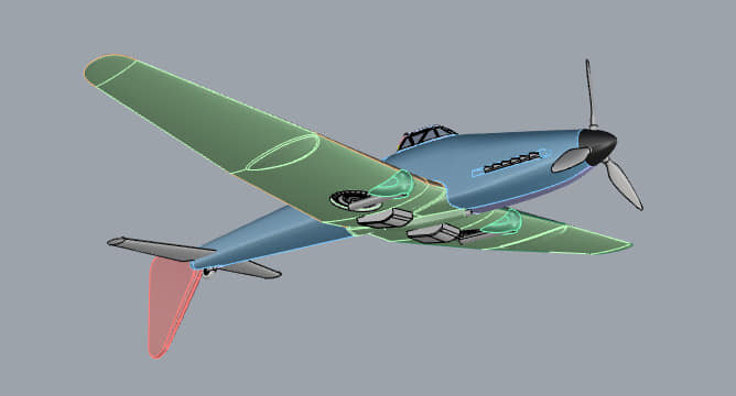
And this is the Ju 187 (see below), about which very little is known. It's really not clear how this fin was supposed to work.​
View attachment 656107
That looks like a Ju 87 windtunnel model that was modified to test the aerodynamics of the proposed configuration. The regular vertical fin and rudder have simply been moved to the bottom of the fuselage, note that the horizontal stabilizer struts are still affixed.The fixed landing gear has been removed and the cowling reshaped. The vertical fin and rudder of the model not being intended as an accurate physical representation of the movable assembly, just a stand in used to determine possible effects on stability and drag when in the lowered position. Rebuilding an existing windtunnel model isn't unusual.
 
Last edited:
That looks like a Ju 87 windtunnel model that was modified to test the aerodynamics of the proposed configuration. The regular vertical fin and rudder have been simply been moved to the bottom of the fuselage, note that the horizontal stabilizer struts are still affixed.The fixed landing gear has been removed and the cowling reshaped. The vertical fin and rudder of the model not being intended as an accurate physical representation of the movable assembly, just a stand in used to determine possible effects on stability and drag when in the lowered position. Rebuilding an existing windtunnel model isn't unusual.

Seems like a plausible explanation to me.
 
The closest match to the Ju 87 wing airfoil is the Göttingen 601 and the flap appears to be the same airfoil.

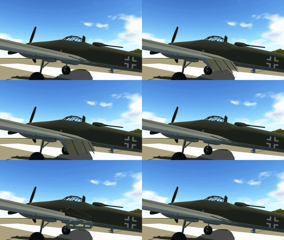
Now, here is the odd part; Ju 87 rigging diagrams call for the flap to be 7 deg nose down in the cruise position. This results in the flap being highly downloaded in cruise:
Ju 87B-2 Rigging 3.png
Ju 87 2D aero.png
 
Hi,

Now, here is the odd part; Ju 87 rigging diagrams call for the flap to be 7 deg nose down in the cruise position. This results in the flap being highly downloaded in cruise:
View attachment 776268
View attachment 776269

Could it be that this is a question of measuring method and reference line?

The diagrams for flap and aileron have somewhat cryptic text on them, "Rm. Bez. E. parallel" and "Bez. E. Querruder". The former is probably something like "Rm-Bezugs-Ebene" ("Rm" reference plane ... not sure what "Rm" stands for, "räumlich"/spatial would come to my mind, but that's too unspecific I'd say.) "Bez. E. Querruder" ist "reference plane aileron".

The 7 degree "Einstellwinkel" (angle of incidence) appear to be measure against the flat aft part of the control surfaces' undersides, though. I believe some aircraft manuals actually have drawings of templates for measurement rigs, it might be that in this case the flat lower surface made this superflous.

With regard to the negative angle of incidence even on the Ju 52, I tried to google the relevant Junkers patent, which should go by the name of "Doppelflügel" (double wing), but had no success so far.

I seemed to remember that the Miles Messenger, equipped with Youngman flaps that are similar to the Junkers Doppelflügel, also has flaps that are set to a negative angle of incidence in cruise position, and the Youngman flap patent at least I was able to find:

https://patents.google.com/patent/US2252656A
From the patent text:

"In dive bombing, it is a great advantage to increase the drag without increase in lift or pitching moment, and it has been found that depression of the nose of the flap or winglet to give a negative incidence relative to the main wing, increases the drag without such a large increase in lift as when the trailing edge is depressed, and also the pitching moment of the combined wing and flap is considerably less."
Of course, you wouldn't want to increase drag in cruise, but as no specific angles are stated here, this wouldn't necessarily rule out that a small negative angle of incidence of the flaps might actually be beneficial in cruise, too.

Regards,

Henning (HoHun)

 
On gliders with flaps, you raise the flaps to decrease lift and drag to increase speed. Full scale flapped gliders use negative flap to cruise between thermals and positive flap to slow down in thermals. Discus launched model gliders use negative flap to generate as little lift and drag as possible during launch for maximum height, which is the highest speed it will achieve in its flight.
 
Experimental modification for a Junkers Ju 87 D3 to deliver spies behind enemy lines, 1944. Up to two people in each pod (plus equipment); they would be airdropped and land by parachute. Program was cancelled due to issues with the deployment mechanism.


Looking for information and original sources for the below attached documents.
 

Attachments

  • Ju 87 Passenger Pods - III.jpg
    Ju 87 Passenger Pods - III.jpg
    46.4 KB · Views: 36
  • Ju 87 Passenger Pods - II.jpg
    Ju 87 Passenger Pods - II.jpg
    27.5 KB · Views: 32
  • Ju 87 Passenger Pods - I.jpg
    Ju 87 Passenger Pods - I.jpg
    48.5 KB · Views: 33
  • Ju 87 Passenger Pods VI.jpg
    Ju 87 Passenger Pods VI.jpg
    26 KB · Views: 37
  • Ju 87 Passenger Pods V.jpg
    Ju 87 Passenger Pods V.jpg
    26.7 KB · Views: 38
Hi all

on "wwii.modeller.co.az" I look at this photo !

What is that ?
A mock up or the first fin tail projects ?

thanks........I don't know !

A few years ago I made a modification on the schematic cut of the Ju-87 to recreate that of the Ju-87V1, although its drifts were different, those in the image seem to be from the early model, I share with you with the permission of the moderators that Cutaway Junkers Ju-87V1 2 vis
 

Attachments

  • Cutaway Ju-87V1 modified by Motocar.jpg
    Cutaway Ju-87V1 modified by Motocar.jpg
    638.4 KB · Views: 71
Last edited:
Hi,

can I ask about something, was there early Ju-287 designation,which
used for a development of Ju-87 or not?.
 

Similar threads

Back
Top Bottom