Grumman Naval Aircraft Design Concepts
Evolving From Current F-14 Versions

STANLEY W. KANDEBO/BETHPAGE, N. Y.

Tomcat21.jpg
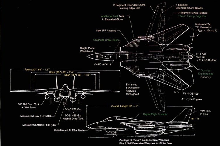
Extended glove vanes and a slightly larger horizontal stabilizer are two external features that distinguish the Grumman Super Tomcat 21 from the F-14D. The aircraft is an advanced tighter based on the F-4D. A dedicated attack version at the Super Tomcat 21 also has been defined.

Design concepts developed by Grumman for emerging U. S. Navy fighter and attack requirements center on several advanced versions of the F-14 incorporat- ing evolutionary upgrades that can be added, in building block fashion, to the existing F-14D.

Although Grumman has been working on F—14 upgrades that would improve upon the current F-14D for several years, the latest designs and configurations were developed at the Navy’s request following cancellation of the A-12 attack aircraft program and postponement of a naval version of the advanced tactical fighter. “Grumman’s ground rules though were that each evolution had to be retrofittable into the F-14D,” Paul C. Bavitz, Grumman’s vice president for advanced F-l4 programs, said. This approach would allow the Navy to improve the aircraft through periodic block upgrades that it could define based on budgets and cost. This method also would allow the service to continue building F-14s until it decides where naval avi- ation should go, he said.

The evolutionary progression of the F- 14, defined by Grumman includes:

F-14 Quick Strike, an aircraft that improves the strike capability of the F-14 by adding stand-off weapon capability and more radar modes to the basic F-14D design. The improvements, which are common to technologies found in the F-15E and A-6F, could be retrofitted into all F- 14Ds. Design options also could improve survivability and reduce aircraft vulnera- bility. Super Tomcat 21, a fighter with improved engines, cockpits and sensors; increased-lift wing slats and flaps, and greater internal fuel capacity. This design also would address F-14 vulnerability, reliability and maintainability issues. The Super Tomcat 21 would feature al- most an order-of—magnitude reduction in the F-14D’s vulnerable areas. The aircraft also would incorporate a single-point maintenance panel, improved diagnostics and upgraded servicing systems that, when combined with its advanced avionics, would reduce unscheduled maintenance manhours per flight hour 40% when compared to the F-14A.

Attack Super Tomcat 21, a dedicated, interim attack aircraft derived from the Super Tomcat 21 that is capable of Mach 2 at high altitudes and 600 kt. speeds without afterburner at low altitudes. This attack aircraft, which would incorporate the Super Tomcat 21’s improvements and retain the fighter’s gun, also probably could carry the radar developed for the A-12. Adding thicker outer wing panels would boost the at- tack aircraft’s capability to carry fuel in- ternally. In addition to the Quick Strike and Super Tomcat 21 family, a more revolutionary strike fighter called the ASF-14 also was considered. With an R&D cost of about $4 billion, this aircraft could be de- veloped as a lower cost alternative to the naval version of the advanced tactical fighter by incorporating ATF engines and electronics into the F-14 airframe. It has received less attention in recent months than the other F-14 derivatives, Bavitz said. The Quick Strike retains the F-14D’s four fuselage rails, each with five substations, and the two wing weapon pylons, both with two substations, as well as the F-14’s two nacelle drop tank stations. Ac- cording to Bavitz, this aircraft configuration, which was studied before the A-12 was canceled, offers the Navy options to improve the ground attack capability of the F-14. Development costs could be $100-200 million, depending on the options select- ed. It would take about two years to develop and test the required software, and a Quick Strike aircraft could be available about one year after that, he said. A key aspect of the QuickStrike would be improvements made to the F- l4’s Hughes AN/APG-71 radar. Several of the improvements—including a synthetic aperture radar mode for high-resolution ground mapping; a Doppler beam sharpening mode for wide-sector, medi- um-resolution ground mapping; and a fixed target track mode—were developed for the F-15E’s AN/APG-70 radar and could be transitioned to the F-14 easily, Bavitz said. A sea surface search mode and a terrain avoidance feature would require some development, however, he said. Other sensor changes to the aircraft include addition of a Flir navigation pod and a targeting Flir pod that includes a laser range finder and designator. The Flir pods could be mounted on the aircraft’s wing pylons. Stand-off weapon capability could be added by modifying the F-14D’s stores management system. The required software for this change and the necessary weapon interface card for the F-14D’s encoder/decoder box would be based on items developed for the A—6F, Bavitz said.

The AYK-14 mission computer software required for aircraft radar and weapon controls, as well as the necessary display system software changes, also would be based on work done for the A- 6F, he said. These changes would allow the aircraft to carry laser-guided bombs, imaging-infrared Maverick missiles, Stand-off Land Attack Missiles and the data link pod required for SLAM control. Predeployment improvements scheduled for the F-14D already add Harpoon and HARM capa- bility, Bavitz said.

Other aircraft improvements would center on the cockpit, where color displays, a digital color map system and a head—up display for the Flir, all night-vision compatible, could be added. To increase mission radius, the aircraft’s wing pylons, already fitted with plumbing to handle drop tanks, could be fitted with a pair of 300-gal. drop tanks. They could also be fitted onto the aircraft’s aft fuselage weapons rails, which would allow Flir sensors to be carried on the pylons. This added fuel would in- crease the combat radius of the Quick Strike by about 80 naut. mi. when compared to the F-14D, Bavitz said. The two aircraft receiving the most attention from the Navy, however, are the Super Tomcat 21 and Attack Super Tomcat 21. According to Bavitz, a Super Tomcat 21, which, depending upon the mission, would have a flight radius 50- 100% better than the F-14D’s, could be built and begin flight test in about three years. Production deliveries could begin in about six years.

Grumman estimates the R&D cost of the aircraft and its sensors at “somewhat less than $2 billion,” which is about half the price the Defense Dept. plans to spend on F/A-18E/F airframe R&D. Central to the Super Tomcat 21 design is an improved high-lift system consisting of a composite single-slotted Fowler flap and a blunter, extended chord composite slat that more than compensates for the 2,000 lb. this design adds to the zero- eight of the F-14D. Grumman and the Navy have wind-tunnel-tested this system twice, and each time they found it pro- duced 25% more lift, through maximum angle of attack, than the current system did. With 25% more lift and only 5% more weight, this aircraft—equipped with two 280-ga1. drop tanks—could be launched from a carrier with zero kt. of minimum wind across the deck, Bavitz said. Air- craft recovery speeds are about 15 kt. lower than those of the F-14D, and the bring- back capability of the Super Tomcat 21 is about 2.5 times that of the A-6, he noted. Other external changes to the aircraft include using the F-14’s inboard wing gloves for fuel storage, a modification that requires an increase in the trailing edge of the aircraft horizontal stabilizer. But using the glove areas for fuel storage adds about 2,200 lb. of internally carried fuel. With two 280-gal. nacelle-mounted drop tanks, which the F-14 regularly carries and retains during supersonic flight, and two 300-gal. drop tanks mounted on the aircraft’s wing pylons, a Super Tomcat 21 armed with four air-to—ground and two self-defense missiles could be launched from a carrier carrying slightly less than 28,000 lb. of fuel. If 425-gal. nacelle-mounted drop tanks are substituted, more than 28,000 lb. of fuel can be carried. And increasing the size of the nacelle tanks does not affect weapons car- riage or release.

According to Bavitz, all mission calculations and signature characteristics were developed with each size of nacelle drop tank installed. The aircraft also can land on a carrier with both size tanks, he said. Gas turbine changes in the Super Tomcat 21 center on the installation of an aux- iliary power unit (APU) and use of a new powerplant, a version of General Electric’s F1 10-GE-129 improved performance en- gine adapted for the Navy. This power- plant would provide about 35% more thrust in mid-altitude, transonic flight conditions than the F110—400 engines now in the F—14D can provide. The new engine also would allow the aircraft to supercruise at about Mach 1.3 while carrying four air- to—air missiles, Bavitz said.

NOZZLE NEED REDUCED

A vectoring, axisymmetric engine exhaust nozzle also is a possibility, but the high angle of attack capability demonstrated by the F-14—77 deg—reduces the need for this type of nozzle. The APU was positioned where the F- 14D’s vent tanks are located, requiring the tanks to be moved to the vertical sta- bilizers. Inside the aircraft, the crew stations would feature large multicolor displays, helmet-mounted displays and sights, and a single-piece windscreen (AW&ST Apr.1, p. 17). Aircraft controls would be upgrad- ed to an electronic system. Very-high- speed integrated circuit (VHSIC)pro- cessor modules would be used to improve signal processing throughput and increase memory capacity. The processors also would be used to fuse all aircraft sensor data, providing one track for each target, regardless of which sensor is following the target. A shortfall in the F-14D, which has only sensor correlation capability, is that each sensor generates a track for each tar- get. VHSIC processors are considered a low-risk development item because they have been demonstrated in AYK-14 mis- sion computers, Bavitz said. Aircraft data links probably would remain the same as in the F—14D, with joint tactical informa- tion distribution system and the ASW— 27C being used. The most substantial changes to the aircraft are in the sensor area, however. The aircraft would incorporate a multimode radar that employs two-dimensional, passive, electronically scanned array technology. This would double the power of the AN/APG-71 radar now in the F-14D. It also could be equipped with inverse synthetic aperture radar and ground-moving target indicator modes. Other technologies could double the detection capability of the radar, Bavitz said.

Infrared search and track systems and a television camera system would be re- tained, and a navigation Flir and an at- tack Flir with a laser rangefinder/target designator would be added. For signature and drag reduction, the Flirs would be installed on either side of the aircraft in fairings ahead of two weapon launch rails, Bavitz said.

In addition to signature reduction techniques, other items will be added to improve survivability. The Super Tomcat 21 would carry more than twice the expendables, boosting the chaff/flare packets carried on the F—14D from 60 to 135. And if additional expendables are required, 320 more packets of BOL chaff can be carried in LAU-7 launchers. These would be mounted on the aircraft stations that normally carry AIM-9 missiles. “Almost half of the 2,000 lb. added to the aircraft were due to survivability items,” Bavitz said. The aircraft also would be equipped with an ALQ-l65 jammer with two trans- mitters, one being dedicated to low-band jamming. The F—14D now is equipped with a version of the jammer that has a single transmitter. The attack version of the aircraft, the Attack Super Tomcat 21, would be highly common with the fighter aircraft, and would retain most of its features, including the aircraft’s M61-A1 20—mm. gun and 700 rounds of ammunition, improved performance engines, APU, survivability improvements, advanced cockpits and improved high-lift system. The attack ver— sion would contain several more features that would improve strike capability. Global positioning satellite navigation capability would be added and when coupled with a terrain following/terrain avoidance radar mode, a navigation Flir, a digital data-driven moving map and a wide field of view head-up display, the aircraft would be capable of making high-speed, low-altitude penetrations. As an altemative, the radar developed for the A-12 could be installed, an option unavailable for the F/A-18 due to the size limitations of the aircraft, Bavitz said. The Attack Super Tomcat 21 would be capable of low-level speeds of 600 kt. without afterbumer and 700 kt. in full afterbumer while carrying ground attack weapons, Bavitz said. In an antisurface warfare configuration, the aircraft would be equipped with two HARMs, four Harpoons, two self-defense missiles and two 280-gal. nacelle-mounted drop tanks. The aircraft, which could de- liver nuclear weapons, also could carry up to 24 Mk. 82 bombs, 14 Mk. 83s, six Mk. 84s or six Harpoons on its fuselage and wing pylons.
AWST 29 April 1991
 
Last edited:
I've seen this question answered three different ways.
1. The variable intake ramps enable speed above Mach 1.8 were incredibly maintenance heavy and they were "fixed" in place in the 90s as a cost savings. Though perhaps they are conflating the intake ramps with the glove vanes?

2. With the F-14Bs higher airflow F110engines they re-profiled the intake ramp geometry for the additional air flow at the cost of top end speed.

3. The Mach 1.8 limit was more structural longevity/safety. The thermal stress above Mach 2 would delaminate the canopy and stress the skins.
https://www.facebook.com/groups/Grumman.F14.Tomcat/posts/3428469360727461/

Point one is slightly correct. The boundary layer dump vent at the top on the duct exhausting up onto the overwing fairing was originally actuated by a hydraulic ram to vary the exit area. The ram was later replaced by a fixed link which fixed the exit area at about 100 square inches.

The inlet ramps were functional on all F-14 variants to the end of the life of the airplane. You can see the wipe marks left in the inlet sides by the ramp seals in any museum bird that has not been repainted. Ramps were cycled to physical (not flight) limits in OBC during aircraft startup.

The glove vanes were fixed (made inoperable) in the F-14As and never included in the F-14B's and D's (both the conversions from A's and new build production airframes). Which caused an embarrassing oopsie when the first F-14B (then F-14A+) got down to Pax River and the the testers found that the change had gone though the system and no one had run a formal stability val/ver effort though Flight Test. That was rectified quite quickly. Removing the glove vanes neatly opened up some space for the ALR-67 RWR gear that was later added.

- Point two. I can't speak to this.

- Point three is probably close to correct. Short story (long story TLDR): late in life, some of the older F-14 aircraft were suffering honeycomb delamination in the Rohr-built inlet module assemblies. 20+ years after fabrication and fleet use/abuse, it was impossible to determine if these were due to quality escapes ("Friday afternoon/Monday morning" units) or later damage. The F-14 was not alone in these problems; IIRC, a F-15C was lost or almost lost south of Eglin AFB during a low-altitude, high-Q flight when a horizontal stab delaminated and explosively disintegrated. Has anyone noticed that classic aluminum honeycomb skins are no longer used on high performance aircraft?
 
Last edited by a moderator:
From what I have read the original Hornet 2000 concept was really just supposed to be a larger, longer ranged replacement for the Hornet, while upgraded Tomcats or a new design (NATF, A/F-X) would fill the air superiority role. At some point the Navy abandoned that plan in favor of what has become the Super Hornet.

I like the Super Hornet, and I think it can do the job well, but in several years I think we will need a true Tomcat replacement, perhaps the F/A-XX can be that.
 
in several years I think we will need a true Tomcat replacement, perhaps the F/A-XX can be that.
FAXX is pushing more towards strike, but is supposed to be able to do BARCAP as well.
 
Here's a start with Post #289
From Aviation Week & Space Technology, September 21, 1981
I have tried to locate another reliable source with the same description, such as announcements published by the USN or Grumman, but no relevant records exist, which is why I suggest further checks(possibly due to flawed search approaches). Such a huge modification is equivalent to the upgrade from the classic bug to the super bug. Logically, this news should not be exclusively reported only by Aviation Week & Space Technology.
 
Point 1 is correct, 2 and 3 are not.

On point 2, The Tomcat's inlets were designed for a 30,000 lb thrust engine from the start. (Sandboxx's info is wrong on this point).
On point 3, the F-14 airframe and the canopy in particular was designed for mach 2.4+. I've certainly never heard or seen anything to suggest there were delamination/structural issues from mach 2+ flight, and I worked on the Tomcat.
My thoughts on the three points cited by Sir isayyo2 are as follows.
Regarding point one. I think it's a conflation of two separate design elements. This citation appears to mix the inlet-top Bleed Door with the Glove Vane. The Bleed Door is described as a two-positioned bleed door in the NAVAIR 01-F14A-1 preliminary flight manual, but is described as a fixed bleed door in the NAVAIR 01-F14AAA-1 manual for production variant F-14A . This indicates that between 1970 and 1972, the bleed door was modified from a movable part to a fixed one due to undisclosed reasons((possibly cost-related?).The removal of the Glove Vane occurred in the 1980s. For these reasons, I am dismissing the first point as invalid.

Regarding point two. As for the second point, I have seen claims that the inlet ramp schedule of the F-14B/D was modified to enhance transonic performance, yet this adjustment also capped the aircraft’s maximum speed. However, I have not discovered any matching records in official documents such as flight manuals, so I do not endorse this view.

Regarding point three. The F-14 fleet suffered extensive airframe aging by the 1990s. Personally, it is plausible that maximum speed limits were imposed to slow fleet deterioration, consistent with the airframe aging issues illustrated by Sir AIM9Xray. Therefore, I consider the third point valid.

Wait!! A thought just occurred to me: Sir SCAT-15F, did you mean to suggest that the removal of the glove vanes increased severe supersonic drag, thereby reducing the maximum speed of the F-14A/B/D variants? If so, is there any official evidence—such as documents from the NAVAIR or Grumman?
 
Last edited:
Wait!! A thought just occurred to me: Sir SCAT-15F, did you mean to suggest that the removal of the glove vanes increased supersonic drag,

Yes as a secondary effect; without the vanes to counteract Mach tuck, the tailplanes had to be deflected from their neutral position which increased aft-end drag.

But the vanes were primarily designed to meet the draconian spec, and when in service that extra margin of Mach 2+ manoeuvrability couldn't justify the complexity of the vanes' hydraulics, controller and position-comparator computer. The reshaping of the beavertail compensated for the increased supersonic drag to an extent.
 
On point 2, The Tomcat's inlets were designed for a 30,000 lb thrust engine from the start. (Sandboxx's info is wrong on this point).
On point 3, the F-14 airframe and the canopy in particular was designed for mach 2.4+. I've certainly never heard or seen anything to suggest there were delamination/structural issues from mach 2+ flight, and I worked on the Tomcat.

The F-14A was flown to mach 2.41 in official testing, and the top speed with TF30's installed was always listed as mach 2.4. Also, there are at least two pilots who flew the operational A-model to mach 2.5; "Charlie" Brown being one of them. Only a stripped-down F-15 has managed to hit that number, so in reality the F-14A is just as much a mach 2.5 aircraft as the F-15 is.
In fact, the TF30 performs better at that speed than the F100 (look no further than the F-111F; a more honest mach 2.5 aircraft than the F-15. It even had built in airframe temperature sensors to specifically limit time at mach 2.5).

The F401, BTW underwent a 24 hour simulated test at mach 2.4 specifically for the Tomcat installation.

The F110-GE-400 installation did have somewhat higher drag. That was intentional as they evaluated 3 tailpipe lengths and chose the middle length as a compromise. The longer one had the lowest supersonic drag and the short one had the lowest subsonic drag.

Regarding weight, the F-14A was supposed to be 36,000 lbs empty but was overweight from the first protoype. With the TF30-P-412's it weighed 40,100 lbs. That grew to 43,500 lbs in the D.

Recall the F-35A was supposed to be 26,000 lbs but ended up at over 29,000.

With the F401 engines installed, the F-14 empty weight was the lowest of any variant at approximately 38,600 lbs. Ship number 7 (now on the Intrepid) flew with the F401's in 1973, and in that non-weapon system equipped test configuration was likely right around 36,000 lbs empty.
This was by far the highest performance Tomcat ever flown. In 1973. It also had the ability to pull 7G at mach 2+ because it had the wing glove vanes, which the B, D and ST-21/variants deleted.

The ST-21/variants would have been at least 46,000 lbs empty even with added use of composites, and with the added drag from the modified wing gloves (to say nothing of all the air to ground paraphernalia) would have completely erased any gains from the -429 engine (or even a -432, for that matter).
The F119 idea made much more sense, but only if they also turned the Tomcat into a full-FBW aircraft actually reducing weight and enabling greater internal fuel without bulging out the wing gloves.
Sir, I have some information to share with you, as I still have several questions remaining.

1. Regarding speed.

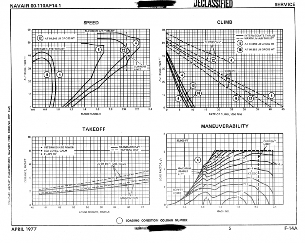
Both the 1974 and 1977 F-14A SACs indicated a maximum speed of Mach 2.4, but also specified a current limit of Mach 2.05. I personally believe this was to prevent TF30 engine failure or an additional speed limit set by NAVAIR for flight safety.
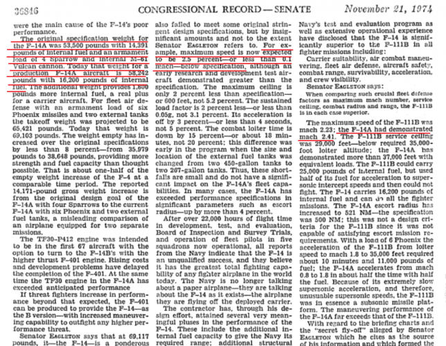
Records from the 1974 congressional hearing show the F-14A demonstrated an actual speed of Mach 2.41. However, the same document also notes that the production F-14A’s real maximum speed is 0.1 Mach (or 2.5%) lower than the original specification. Could you please advise what the maximum speed requirement was stated in the original specification?

2. Regarding weight.

According to the same hearing documents, the F-14A’s weight in the original specification configuration (14,391 lb internal fuel + 4 AIM-7 missiles + M61 cannon) was 53,500 lb. As of 1974 (which I believe is the "today" referenced in the document), the F-14A carried 16,200 lb internal fuel along with AIM-7 missiles and the M61 cannon, with an actual weight of 58,242 lb. Meanwhile, the empty weight of F-14A was also increased from the original specification value of 35,979 lb to 38,648 lb by 1974. Additionally, the Preliminary Flight Manual NAVAIR 01-F14A-1 (June 1972) lists the zero-fuel/stores gross weight of F-14A is approximately 37,781 lb. Internal fuel capacity is approximately 16,000 lb. I have two related questions: What was the purpose of expanding the internal fuel capacity, Or was the original internal fuel volume insufficient to meet the designed range requirement? Furthermore, was all of the weight growth during this period solely caused by the increase in internal fuel?

3.Regarding exhaust nozzle configuration.

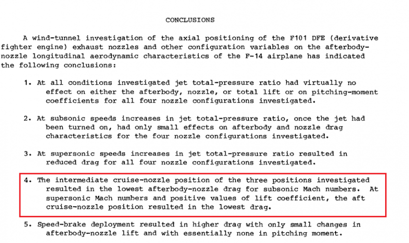
According to the NASA report released in March 1982, titled Effects of Installation of F101DFE Exhaust Nozzles on the Afterbody-Nozzle Characteristics of the F-14 Airplane, the intermediate cruise-nozzle position yields the minimum drag at subsonic speeds, while the aft cruise-nozzle position provides the lowest drag under supersonic positive lift conditions. Additionally, this aft cruise-nozzle position originates from the original design intended for the F401-PW-400 engine.
 

Attachments

  • 0f9df23c-2acd-4280-aa79-f407504f09da.png
    0f9df23c-2acd-4280-aa79-f407504f09da.png
    1.4 MB · Views: 76
  • b9641b16-33fa-4827-a5b7-bb6ed4da2061.png
    b9641b16-33fa-4827-a5b7-bb6ed4da2061.png
    196.6 KB · Views: 53
  • da2bdfb6-3ec4-4a06-aff3-b3dab7d26917.png
    da2bdfb6-3ec4-4a06-aff3-b3dab7d26917.png
    922.8 KB · Views: 72
AWST 29 April 1991
Hi all - long time lurker!

Sorry to sidestep for a second, but I am looking for as-high-quality-as-possible planviews of Tomcat-21. I do illustrations for a dogfight boardgame: Birds of Prey, and have been tasked with rendering the Tomcat-21 for the upcoming yearly convention.

if anyone can provide some links, definitive references or even scans, this would be greatly appreciated!

.Morten
 
The AN/AAS-42 is actually capable of supporting AIM-54 launches. Judging by the descriptions in these two videos, the AN/AAS-42 is truly a "game-changer" in air combat. Based on the details provided, the AN/AAS-42 appears to employ angle-only TMA (Target Motion Analysis) for range estimation; however, it is unclear how the system mitigates the errors inherent in long-range ranging with a single sensor. Alternatively, could two F-14Ds be performing TMA by networking via Link 16?


Attachments

  • AAS-42 ranging.png
    AAS-42 ranging.png
    53.7 KB · Views: 73
Based on the details provided, the AN/AAS-42 appears to employ angle-only TMA (Target Motion Analysis) for range estimation; however, it is unclear how the system mitigates the errors inherent in long-range ranging with a single sensor. Alternatively, could two F-14Ds be performing TMA by networking via Link 16?

It's probably kinematic range, somewhat like triangulation of a target, using ownship movement and angular rate changes of the target. That requires an offset to the target to generate the angular change, unless the target isn't head-on. Takes a while to resolve range satisfactorily. Exchanging bearing data over LINK16 is theoretically possible, whether it was a thing at the time is another question.
 
It's probably kinematic range, somewhat like triangulation of a target, using ownship movement and angular rate changes of the target. That requires an offset to the target to generate the angular change, unless the target isn't head-on. Takes a while to resolve range satisfactorily. Exchanging bearing data over LINK16 is theoretically possible, whether it was a thing at the time is another question.
Based on Jungle's description in the video "Flying the F-14D Super Tomcat" (specifically between the 17:40 and 18:00 marks), he would push his wingman out about 10 miles; by exchanging bearing lines via Link 16, they could determine the target's precise location. I believe that the concept of utilizing Link 16 for what is now known as cooperative passive ranging was already being implemented at that time.

I am also curious whether passive mode could support long-range AIM-54 launches for "fleet defense missions."
 
Here are several stories about the F-14 Central Air Data Computer (CADA). Doing a site search, nothing much has been posted about the topic. One of the YouTube videos was linked back in April 2022. This will add some needed info about this important piece of the F-14.

The first story one talks about the CADA operation and function. Tom's Hardware did two stories about the CADA that compliment the others. The other ones are about the designer Ray Holt.

The World's First Microprocessor: F-14 Central Air Data Computer
View: https://www.youtube.com/watch?v=YpruA5mC7wg


The MP944 was the 'real' world's first microprocessor, but it was top secret for nearly 30 years — F-14 Tomcat's chip lived in the shadow of the Intel 4004, but was eight times faster
https://www.tomshardware.com/pc-com...-shadow-of-the-intel-4004-for-nearly-30-years

3D-printed F-14 Tomcat uses an FPGA recreation of the 'world's first microprocessor' — CADC's MP944 chip controls the fighter's swing-wing system, among other things
https://www.tomshardware.com/pc-com...fighters-swing-wing-system-among-other-things

Ray Holt and the CADC – The World’s First Military Digital Flight Computer
https://www.eejournal.com/article/r...orlds-first-military-digital-flight-computer/

Ray Holt and the Lost History of the First Multi-Chip Microprocessor
https://www.eejournal.com/article/r...story-of-the-first-multi-chip-microprocessor/

Ray Holt and the history of MP944/Cadc @ Rome Technopole, 2017
View: https://www.youtube.com/watch?v=3GROYRkWvxc


Ray Holt Oral History
View: https://www.youtube.com/watch?v=dxvcBa2RIbU


Ray Holt Oral History (Transcript of YouTube video "Ray Holt Oral History")
https://www.computerhistory.org/collections/catalog/102792868/
 
Good questions.


This is a spring-loaded flipper door for the ECS Ram Air Inlet. It is hinged at the bottom and is opened by air loads in flight. On the ground, the Ram Air Door stays closed and a fan sucks air thought the [grilled] ECS Aux Air Inlet to prevent FOD ingestion.

The MiG-29 later adopted the same strategy to prevent engine FOD ingestion during ground operations.


"the armrest handgrip on the pilot canopy windshield frame."

The HUD on the F-14A/B was designed specifically for the the Tomcat as part of the Vertical Display Indicator Group (VDIG).

The HUD on the F-14D (along with the MFDs, DPs, SMS etc) was hardware that was originally designed and for and used in the F-18A and its cockpit. (And was to be also used on the A-6F for cost saving.) As such, the space under the windshield of the F-14 (front to back) was a little shorter than that of the F-18, so the combiner glass assembly intruded into the cockpit slightly*. The handgrip on the windshield frame was removed so you didn't break the combiner glass(es) when installing or removing the HUD.

The discussion is about the same for the F-14B Upgrade which removed the old HUD from the VDIG chassis and replaced it with the existing Sparrowhawk HUD (creating the VDIG/R unit).

So, in both cases, it was much cheaper to use the off-the-shelf hardware that was already qualified than to modify the HUDs to remove the combiners. (IIRC, the center windshield glass did have to be replaced for HUD compatibility - but I may be misremembering.)

*there is also some criticality about the fore/aft placement of the HUD "eyebox", that area where the pilot's eyes have to be for best viewing of the HUD imagery (this being a fixed position aft of the combiners) - but discussion of that is above my paygrade.

Here is an advert for a predecessor Smiths HUD to that used in the F-18. As you can see, there is more to the unit than just the combiner glass and up-front control that you have to stuff under the windshield!
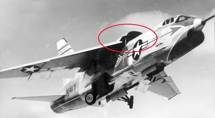
Not the same but similar confusion that has been haunting me for looonge period is why there was frontal surface also appeared on F-8 Crusader looks like a siginificant drag area against her taking off. Is this a pure blunder or there was a trick never photographed?
 

Attachments

  • 531L.jpg
    531L.jpg
    45.3 KB · Views: 43
It is a trade-off. On take off, the increased wing incidence helps the wing generate more lift for easier take off, with better visibility over the nose. After the aircraft clears the deck/runway the wing lowers into the fuselage, reducing drag, allowing for easier acceleration. On landing, you gain an extra air brake.
 
It is a trade-off. On take off, the increased wing incidence helps the wing generate more lift for easier take off, with better visibility over the nose. After the aircraft clears the deck/runway the wing lowers into the fuselage, reducing drag, allowing for easier acceleration. On landing, you gain an extra air brake.
Not quite, the wing is where the lift is. It pulls the fuselage up. That's why you wouldn't have to make the pivot mechanism stronger if you put stores on the wing, like on Marine Crusaders with wing pylons, but would if you put significant extra weight on the fuselage.
 
at least 46,000 lbs empty even with added use of composites, and with the added drag from the modified wing gloves (to say nothing of all the air to ground paraphernalia) would have completely erased any gains from the -429 engine (or even a -432, for that matter).
The F119 idea made much more sense, but only if they also turned the Tomcat into a full-FBW aircraft actually reducing weight and enabling greater internal fuel without bulging out the wing gloves.
Even if the F‑14 were changed to FBW, I strongly doubt there would be remaining internal volume within the airframe to increase fuel capacity. Referring to the fuselage cross‑section drawings from the Flight Manual, I believe the rapidly tapering contour of the F‑14’s aft fuselage reduces internal volume, which in turn limits its internal fuel load.

Additionally, I would like to ask whether Grumman ever developed an F‑15E‑style “glass cockpit” for follow‑on F‑14D upgrade programs. The Grumman Newsletter dated 28 April 1989, in its article “Grumman Unviels New Simulation Lab”, features a distinctive cockpit layout. While the outer cockpit contour clearly identifies it as an F‑14, its MFD arrangement differs substantially from both the production F‑14D and the ST‑21 configuration.
 
Even if the F‑14 were changed to FBW, I strongly doubt there would be remaining internal volume within the airframe to increase fuel capacity. Referring to the fuselage cross‑section drawings from the Flight Manual, I believe the rapidly tapering contour of the F‑14’s aft fuselage reduces internal volume, which in turn limits its internal fuel load.

Additionally, I would like to ask whether Grumman ever developed an F‑15E‑style “glass cockpit” for follow‑on F‑14D upgrade programs. The Grumman Newsletter dated 28 April 1989, in its article “Grumman Unviels New Simulation Lab”, features a distinctive cockpit layout. While the outer cockpit contour clearly identifies it as an F‑14, its MFD arrangement differs substantially from both the production F‑14D and the ST‑21 configuration.

Does it? Front cockpit pretty much looks like F-14D with WAR HUD of the F-16 Blk 40/42 and a third (left) MFD in place of the analogue back-up flight instruments. It might well be that digital engine/fuel indicators might have been used, but that's not really evident from the granny black/white pic of the newsletter. It's noteworthy that the ST21 slides describe 3 x 5in x 5in color MFDs and 4 x 6in x 6in MFDs. I'm inclined to believe the 5in ones were for the front cockpit, the 6in ones for the RIO.
 
Does it? Front cockpit pretty much looks like F-14D with WAR HUD of the F-16 Blk 40/42 and a third (left) MFD in place of the analogue back-up flight instruments. It might well be that digital engine/fuel indicators might have been used, but that's not really evident from the granny black/white pic of the newsletter. It's noteworthy that the ST21 slides describe 3 x 5in x 5in color MFDs and 4 x 6in x 6in MFDs. I'm inclined to believe the 5in ones were for the front cockpit, the 6in ones for the RIO.
I lean toward an overall layout similar to that of the F‑15E: two 6‑inch MFDs for each crew station, plus one 5‑inch MFD in the front cockpit and two 5‑inch MFDs in the rear cockpit. That said, there are no high‑resolution photos available, so I cannot make out the exact configuration. This is why I wanted to ask former Grumman employees on the forum for information regarding this new simulation lab.
 
Such a layout makes sense, but as you said, the lack of proper images makes it near impossible to say. Maybe the MFDs in the granny pic can be overlaid to determine whether or not they are different in size. My reasoning is based on the assumption that the two 5in x 5in MFDs in the F-14D front cockpit would simply be replaced by colored units of the same size.
 
Hello, first let me raise a toast to this beautiful fighter.

I'm looking into NF-14A BuNo 158625.
It fired an AIM-120 on September 23, 1981, It was the AWG-9 modified to support the AIM-120 as well, or was this a launch-only test with no guidance testing involved?
I've read that the AIM-120A could be fired without modification using signals similar to the AIM-7, keeping the existing data bus and other systems unchanged. However, I believe guidance would still have required a radar modification.

Also, when I was talking about the F-14 with a friend, I was told that this same BuNo 158625 became the test aircraft for the AN/APG-71. I haven't been able to find any information on this and have no way to confirm whether it's true. does anyone have any information on this?
 

Similar threads

Back
Top Bottom