In case you are wondering why I keep on about the W2/500..... when Stanley Hooker told Adrian Lombard to get on with the straight through engine to replace the Welland he took the best of the B26 (STx9) and the best features of the W2/500. Using as much of the B23 as possible Lombard's team came up with the B37 Derwent 1.
The improvements in performance of the W2 series came about through the interplay of several factors.
Compared with the W2B the W2/500 had a larger hub/tip ratio which permitted an increase in mass flow. Also fewer turbine blades of longer chord were used; the number used on the W2/500 was 54 each with a chord of 1.4 in., compared with 72 blades of 0.8 in chord. The change to fewer, larger blades was made on the recommendation of the RAE after the W2B suffered a number of turbine blade failures. The new blades were more resistant to the gas bending forces (lower stresses) and minor damage from solid particles passing through the annulus.
Metallurgy was key to development of a light, reliable engine. The advent of Whittle's gas turbine created the need for stronger, more durable alloys capable of high-temperature service When the WU was designed the best available material was Firth-Vickers 'Stayblade' and this was used for both disc and turbine blades. By the time the W1 was on the boards, F-V had produced an improved alloy- Rex 78 and this was used for the blades. But the first to answer the challeng was Leonard Bessemer Pfeil, who is credited with the development of Nimonic alloy 80 in 1941, at Henry Wiggin's research facility in Hereford. This alloy used for the blading was introduced into the later stages of the W2B development programme and in the W2?500 and /700 from the start.
The top two development issues that kept the W2B engineers awake at night were surging of the compressor and turbine blade failures. Some blade failures were a secondary consequence of a failure elsewhere. A piece of combustion chamber that had broken off could pass through the rear of the engine, notching blades on the way and this often led to blade failure. One series of failures was odd. Sometimes blades failed at the root sometimes half way up and occasionally close to the tip. Resonance would be expected to produce failures at the same place. Eventually it was realised failure was caused by a thermocouple mounted in the exhaust duct 3 inches downstream from the turbine. It was adjustable radially across the annulus and Whittle believed that there must be an upstream pressure field ahead of it of sufficient magnitude to interfere with the flow through the blades as they passed through it. It seems this was a correct diagnosis as the failure rate dropped dramatically after the thermocouple had been removed. [but it foretold of a similar problem that occurred during early development of the RB211 some 30 years later].
Another source of grief was the rubbing of turbine blade tips. The running clearance was intended to be small in order to minimise aerodynamic losses; unfortunately it is start-up and shut-down that determines the clearance. For instance at shutdown there is a sudden draught of cold air through the annulus which rapidly cools components of small mass like shroud rings, vanes, and blades but larger items, such as the disc cool more slowly. This means if the running clearances are too small the shroud ring could contract onto the blade tips on shutdown and at worst pick up the melted tip of the blades which would cause bending forces as blades passed over the material or as serious it could just lock up the rotating assembly causing much damage.

 1273413AVIA_13_150_IMG_0002.JPG182 KB · Views: 332
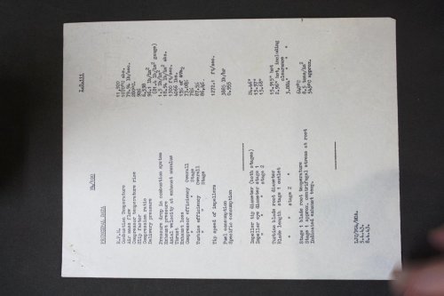 8401388AVIA_13_150_IMG_0004.JPG98.8 KB · Views: 328
 4518934AVIA_13_150_IMG_0023.JPG81.1 KB · Views: 319
 3988850AVIA_13_150_IMG_0024.JPG88.9 KB · Views: 315
 7804722AVIA_13_150_IMG_0025.JPG93.9 KB · Views: 310
 4264280AVIA_13_150_IMG_0026.JPG75.8 KB · Views: 113
") .
.