Early British gas turbine development

There is a description of the Jumo 004 engine here.
Should we have a thread early German gas turbine development?
It states in above link that originally solid Tinidur-derived blades were used but hollow came along afterwards.
Another ref gives this info.
"In 1936, when development work on the Jumo 004 started, a high-temperature Krupp steel known as P-193 was available. This material, which contained Ni, Cr, and Ti, could be given good high-temperature strength by means of solution treating and precipitation hardening. Krupp developed an improved version of P-193 known as Tinidur. It was of the same type as Nimonic 80, which was used in British Gas turbines from 1942 but contained over 50 percent iron (which was replaced by Ni in Nimonic 80) and this caused a rapid drop in creep strength at 1080F (compared to 1260F for Nimonic 80). While Krupp knew that Tinidur could be improved by increasing the Ni content from 30 to 60 percent, there was a recognition that Ni would not be available. The Ni content was therefore left at 30 percent. Similarly, work on cobalt-based alloys was also shelved due to a shortage of cobalt." (Journal of Engineering for Gas Turbines and Power, October 1997, Vol. 119)

The same articles also references the material compositions for both Tinidur and Cromadur:

Tinidur - 15% Cr, 30% Ni, 2% Ti, 0.8% Si, 0.7% Mn, 0.15% C, balance Fe. This composition is similar to today's A286.

Cromadur - 18% Mn, 12% Cr, 0.65% V, 0.5% Si, 0.2% Ni, 0.12% C, balance Fe.

when calculating amount of strength/or degrees of cooling remember that the tet is an average of the traverse across exit root to tip. The actual local temperature will be as much as 200 deg C hotter/colder than this... typically mid span of blade will be hottest in a well designed combustion chamber outlet1
 
Hi
Did the early c1940 Hungarian turboprop use air cooled blades.
/
tartle said:
There is a description of the Jumo 004 engine here.
Should we have a thread early German gas turbine development?
It states in above link that originally solid Tinidur-derived blades were used but hollow came along afterwards.
Another ref gives this info.
"In 1936, when development work on the Jumo 004 started, a high-temperature Krupp steel known as P-193 was available. This material, which contained Ni, Cr, and Ti, could be given good high-temperature strength by means of solution treating and precipitation hardening. Krupp developed an improved version of P-193 known as Tinidur. It was of the same type as Nimonic 80, which was used in British Gas turbines from 1942 but contained over 50 percent iron (which was replaced by Ni in Nimonic 80) and this caused a rapid drop in creep strength at 1080F (compared to 1260F for Nimonic 80). While Krupp knew that Tinidur could be improved by increasing the Ni content from 30 to 60 percent, there was a recognition that Ni would not be available. The Ni content was therefore left at 30 percent. Similarly, work on cobalt-based alloys was also shelved due to a shortage of cobalt." (Journal of Engineering for Gas Turbines and Power, October 1997, Vol. 119)

The same articles also references the material compositions for both Tinidur and Cromadur:

Tinidur - 15% Cr, 30% Ni, 2% Ti, 0.8% Si, 0.7% Mn, 0.15% C, balance Fe. This composition is similar to today's A286.

Cromadur - 18% Mn, 12% Cr, 0.65% V, 0.5% Si, 0.2% Ni, 0.12% C, balance Fe.

when calculating amount of strength/or degrees of cooling remember that the tet is an average of the traverse across exit root to tip. The actual local temperature will be as much as 200 deg C hotter/colder than this... typically mid span of blade will be hottest in a well designed combustion chamber outlet1
 
As promised... the equations for the effect of component efficiency on overall thermal efficiency of the gas turbine.
 

Attachments

  • pl92.pdf
    134.8 KB · Views: 71
Researching about early axial compressor work (starting in 1926!) ...
There is a reference in A McKenzie's technical volume in RRHT books series to the RB106... my belief was only a bit of combustion work was done but apparently a 5-stage LP compressor rig was built. It was RR's first transonic compressor with the first stage having no igv and a tip entry Mach No=1.2 and hub MN=0.75. It had a drop of 5% effy compared with a typical Conway LP which was in contemporary development. In order for Conway to be uprated a zero stage was added and also they also looked at using a transonic design for this. Scaling a stage from the RB106 gave a design that was tested and gave an effy drop of 1% compared with a conventional spool of subsonic blades but the trade-off was that there would be no need to bleed off anti-icing air for igvs and lighter weight. Though the trade off looked positive the design was not proceeded with but it was the start of research that led to the big fans of today.
 
The RCA3 engine which we covered here did in fact progress beyond paper at Derby. The HP compressor was constructed for rig testing- the first multistage axial on a single spool to be designed at Derby (as distinct from the Griffith layouts). It had a rotten performance and at a Hives (Hs) Monday morning meeting when all senior engineers met (including the Barnoldswick ones) it was suggested that it would be better to go for the Metrovick F2 compressor and the Hooker suggested that the HP spool be a centrifugal one. Hs concurred and that was the end of the RCA3 turbofan and the beginning of the Clyde turboprop!
The favoured RCA3 layout was a three shaft engine with a single stage fan ... the relevant section drawings are in patent pdf below...
 

Attachments

  • GB579820A.pdf
    1 MB · Views: 51
In #78 I talked of the WR1 being a gas turbine learning device for RR Derby. In fact it was also useful in the PI engine programme, providing the turbine design, which was scaled for Crecy turbo-blower duty.
 
Ref Proteus anti-icing.
Apologies if this has already been covered. I have searched without luck.

Was the Indian Ocean icing described below of a different kind beyond the capability of the BOAC 'Rabbit Warren' fixes?

Here is an account of RAF Proteus (511 Sqn) icing over the Indian Ocean around 1961.

From the Britannia captain, Nick Carter, in his book "Meteor eject".
"The Proteus engines generated ice...lumps of ice would break away and cause 'engine bumping'..the bumps got louder and could be heard by the passengers...If ignored the engine would flame out, an even greater concern to the passengers who would witness a long tongue of flame as the engine attempted automatically to relight."

With regard to fixes....
He says "The solution was to fit heaters to the intakes which were switched on when flying in cloud within the critical temperature range".

Rod Banks ( I kept no diary p. 188) also says "Eventually the icing problem was cured by fitting Napier electrically heated mats at the bends."
 
I had already read your Rabbit Warren development story as a complete fix for icing before BOAC would accept the engines so two things came to mind when reading those books.

I wasn't expecting to read of engines in service still having an icing problem nor expecting mention of heater mats as a solution.

Presumably the RAF received engines without the mods and accepted the icing until heater mats were introduced?
 
The point I was trying to make was that there were no Napier mats in the solution for the Proteus... the mats were a Britannia solution i.e.
Ice Protection [for Britannia]. There are two major systems: hot air and electric mats. The former utilizes hot gas tapped from between the compressor-and power-turbines of each engine, diluted with air induced from the flow inside the cowling. This mixture is used to heat the leading edge and outer walls of the main cowling and intakes, together with the elbow to the compressor intake and the radial intake vanes. Pre-selected temperature control is automatic. Protection of the wings is also achieved by hot air from the same source.
The complete empennage is protected by Napier Spraymats applied to the leading edges of the tailplane and fin, and on the double-curvature surfaces of the elevator horn balances. They are applied also to the ventilating air intakes in the two upper fixed beams in each engine cowling. Airscrew blades and spinners are heated by internal electric elements. The six forward windscreen panels are also electrically heated by a transparent conducting layer on the outer glass lamination.
Rod Banks, who I once met when he came to discuss an article he was writing on the 'R' engine, called his book 'I kept No Diary' because he kept no diary and when telling a story relied on others to pin down the date and precise details... he obviously remembered the problems but did not differentiate the solutions in this case.... the book is a great record but needs to be checked for exact accuracy.
 
Since writing the original post I have been provided with a RRHT article which may be regarded as 'definitive'

Proteus Icing problem… an article for RRHT by Bryan Williams

The Problem
In the mid-1950s the Bristol Britannia, the first large, long range, four turbo-prop engine powered airliner was entering into service. Subsequent to the development flying, route proving and initial operation, an unexpected meteorological problem was encountered. In temperate regions, particularly over the North Atlantic, no problems had occurred. However on routes through tropical regions to South Africa and the Far East, when flying in cloud at the normal cruising flight level of 20-25,000ft., icing conditions were encountered. Ice built up in the engine intakes, then periodically broke off and passed through an engine, momentarily extinguishing the combustion flames and causing a ‘bump’ which although not dangerous, was uncomfortable for passengers and unacceptable to the airline. The problem was seriously delaying entry into full service, and there was an urgent requirement to understand and fix the problem.

Investigations
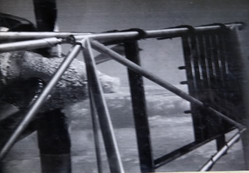
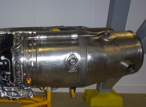
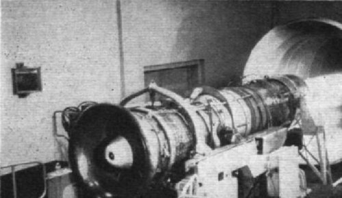
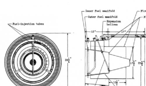
The Britannia used the Bristol Proteus III turbo-prop engine; this was developed from the earlier Mk II version, which had been designed for the Brabazon II and Princess aircraft. To achieve a minimum length, the engine had reverse flow which was retained in the Mk III version. The airflow after entering the forward facing intake, passed along the outside of the engine, and then turned approximately 180° to a forward direction before entering the compressor. It was found that under certain tropical conditions, ice accumulated on the outer radius of this 180° bend, then periodically broke off and entered the engine. Earlier flight tests had included those on an Ambassador aircraft which was re-engined with the Proteus III and fitted with equipment to spray water into the intake under icing conditions. A very early version of closed circuit TV was also fitted which speeded up the test programme as events could be seen immediately during flight, rather than waiting for the processing of film.
This work showed no problem in the inlet duct, only icing on the compressor inlet guide vanes which was dealt with by the anti-icing system fitted. It had also been considered that heat from the core of the reverse flow engines would eliminate any possible icing in the intake duct. In order to understand the problem, a wide ranging investigation involving Bristol Aero Engines Ltd, the Royal Aircraft Establishment Farnborough (RAE) and the Meteorological Office was undertaken.
Flight tests in Central Africa, based at Entebbe in Uganda with the CCTV on an engine confirmed the build-up and shedding of ice. Other instruments were fitted in an attempt to gain data on ambient moisture levels. Within tropical cumulo-nimbus clouds at the flight level, there appeared to be three possible cloud conditions which could be the cause:

1. A super-cooled water droplet cloud with air at above 0°C.
2. An ice crystal cloud well below 0°C (‘dry icing’).
3. A cloud with a mixture of free water and ice crystals, slightly below 0°C (‘mixed icing’).

The first condition could be considered as the conventional low level icing problem. Super-cooled water droplets freeze on impact with an aircraft, giving glazed icing on wings, engine cowling leading edges and propellers and various methods have been developed to remove the ice or prevent the build-up, typically by the application of heat to the surfaces.
During operation in the ‘dry icing’ condition, some of the ice crystals seemed to partially liquefy on the warmer walls of the intake. This enabled the crystals to adhere to the walls, other crystals then coalesced on this base until a piece of ice broke off and was ingested. This process was observed in flight and was also reproduced in an altitude test facility. A similar process in an accelerated form took place in the ‘mixed icing’ condition. Free water moistened the intake surfaces, giving a base for ice crystal adhesion. It appeared that this only occurred when the ambient temperature was somewhat below 0°C. At around 0°C a combination of slightly super-cooled water droplets and ice crystals did not adhere. As glazed ice deposits formed, they were eroded by ice crystals.
The principle variables in ‘dry icing’ and ‘mixed icing’ were total water concentration and air temperature.
Data from instrumentation on the flight tests and altitude test facility runs, showed engine incident rate increasing with concentration levels in ice crystal clouds at various temperature levels. Concentration effects in ‘mixed icing’ conditions were also demonstrated. In this case there were two variables. With low levels of free water it was found that up to a certain level of ice content there was no build-up. As the concentration of ice crystals increased, accumulations of ice growing increasingly large and shedding less frequently were formed. If the free water content was increased at a given ice content, the deposits washed away before reaching any great size.
The ‘mixed icing’ condition was most critical in producing engine incidents, so one aim was to establish if there was a critical value of total water concentration.
Determination of this was difficult, it was not possible to simulate in ground tests and no flight instruments were available to measure ice crystal content in the presence of liquid water. Data from RAE suggested that total water concentrations within the intake of less than 2-4 grms/cu.metre, of which a large proportion was in the form of ice crystals would not cause problems. It was also considered that there could be some ‘enrichment’ in the intake due to crystals and droplets being drawn into the intake. This factor was difficult to assess, but may have been as high as 2 or 3, so implying that the critical concentration in the free air was possibly between 1 and 2 grms/cu.metre at the 20-25,000 ft. flight level. Changes in temperature produced differing results in the ‘dry’ and ‘mixed’ icing conditions. In the former case, increased temperature seemed to increase engine disturbance, probably due to warmer intake surfaces on which ice crystals impacted, melted and coalesced more readily. The latter condition showed a less marked effect, probably due to some water being present on the surfaces over the narrow temperature range involved.
The investigation then attempted to establish the frequency of climatic conditions which produced high concentrations. Unfortunately there was little data then available on the free water content of clouds. It was thought that an estimate could be obtained by analysing rates of rainfall data at points along the aircraft routes, as the rate of rainfall might be related to cloud water content. However data on rainfall rates, as opposed to the total amount of rainfall in a period, was not available in these tropical regions.

The Solution
During the summer and autumn of 1957 there was a period of intense activity to find a solution to this problem.
In addition to ground tests of complete engines, other basic work was undertaken. For example, the compressor alone was run on the electrically driven 3000HP compressor test rig to measure effects of ice ingestion. The best simulation of an incident was obtained by dropping bags of chipped potatoes into the compressor inlet while it was run at speed!
A two dimensional aerodynamic model of the 180°C inlet bend was also made in wood and Perspex. Air was blown through the model and a spray of table salt granules injected into the stream from a pressurised tank, together with a very fine spray of water. This gave a good simulation of ice buildup
(N.B. it had to be Cerebos salt, as for some reason Saxa would not stick!). Various changes to the duct shape were made including weirs and fences on the surface. None of these made any significant difference.
Eventually, a solution was found on this rig. A narrow slot was formed on the outer radius of the bend and a jet of air blown through it which increased the velocity of the boundary layer in that area. After some trial and error an optimum position was obtained. It was then found possible to fit ducting to the engine nacelles to allow warm air to be bled from the compressor to feed similar slots when icing conditions occurred, (they became known as ‘B Skin Jets’). It of course did cause a small reduction in engine performance when operating. Further flight tests in Central Africa and later from Singapore and Darwin confirmed the effectiveness of this method. In addition, glow plug equipment was installed in the combustion system to give an automatic relight, should an event still occur.

Conclusions
These problems over 50 years ago showed the result of an unexpected meteorological condition on the operation of an airliner. It only occurred in tropical conditions where high water contents existed in clouds at the flight level. Eventually the Britannia proved a very efficient and reliable airliner for the time, being in service with several airlines and the RAF for a number of years. This was particularly shown on the North Atlantic routes in the late 1950s. The long range version was the only aircraft then capable of flying consistently westbound from London to New York in virtually all weather conditions without a refuelling stop. The Israeli airline El Al was particularly innovative in developing ‘pressure pattern’ flying, by diverging from great circle flight paths in accordance with forecast upper winds and also increasing altitude as fuel was burnt. They were able to fly eastbound, New York -Tel Aviv, 6,100 miles, without a stop. A serious result of the various delays entering into full service was that sales of the aircraft were limited, as airlines preferred to wait for the pure jets then being developed, (e.g. the Boeing 707). Ironically, after all the work, delays and insistence of the users that the problem must be completely solved, it is believed that the equipment was little used. Aircraft captains, wherever possible, changed course or altitude to avoid flying through tropical cumulo-nimbus cells to minimise general air turbulence and give maximum comfort to their passengers.

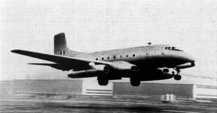
Also this picture [from here] shows the trial in Africa.
 

Attachments

  • De-Ice-proteus.jpg
    De-Ice-proteus.jpg
    52.4 KB · Views: 260
Thank you for your patience and detailed explanations on the Proteus anti icing development.

Are you able to help with these..
1. On the Double Mamba what is the large dia pipe, with flex middle section, going from compressor delivery to exhaust? see photo attachment

2. Had Bristol done any reheat development prior to the Olympus 320?
 

Attachments

  • 169-1.jpg
    169-1.jpg
    251.3 KB · Views: 241
Bristol started looking at adding a reheat system to the Olympus in the mid-50s and decided that as Solar in the USA had a fully variable system available they would look to using this in order to rapidly learn and acquire technology. So in 1956 the Olympus 101 was equipped with a Solar built afterburner designed by Paul Pitt, Solar's top engineer. The 102 was also tested with the afterburner and a 40% thrust boost was achieved; 12,000 lbt dry, 16,800lbt reheated. A formal programme was then agreed to support the development of the TSR2 design. This led to a programme 1959-62 on a 301 modified to reflect higher duty operation (temperature etc). The first tests were carried out using a fully-variable nozzle-equipped 38 inch diameter jetpipe from Solar. It had hydraulic system to control the nozzle. The experience from this enabled Bristol to design and test their own 40.5 inch dia. jetpipe with a pneumatically-controlled fully variable nozzle.
tbc
 

Attachments

  • Olympus 101 with a Solar afterburner-1956.jpg
    Olympus 101 with a Solar afterburner-1956.jpg
    71.1 KB · Views: 201
Interesting story about Solar. They built exhaust manifolds in WW2 and their high-temperature fabrication experience led to them being asked to make afterburners. I had never heard of any other company being a "third party" AB supplier - maybe at the time it made no less sense than putting a GE turbo on a PW or Allison engine - but in fact a quick check shows that Marquardt provided the AB design for the Orenda Iroquois.
 
JIC anyone is curious from museum wanderings (as I was, photo in #251) the Double Mamba tube is not shown on any drawings in this 'Flight' article but the center section from where the tube originates is shown to include bearing vent pipes so maybe it's an overboard breather?
http://www.flightglobal.com/pdfarchive/view/1957/1957%20-%201727.html

On the Solar front around 1953 Solar stabilisers were tested on the RA7 reheat system but gave no benefit over the RR design - ref Cyril Elliott's book.

In 1960 Avro produced a brochure for a Vulcan Phase 6 with two alternative power plants, Olympus with reheat or, more interestingly, with an aft-fan arrangement mounted at the trailing edge of the wing. Ref David Fildes' book 'The Avro Type 698 Vulcan'.
 
LowObservable,
That's right ... as US military were doing the massive build-up of Cold War armaments they were running into development problems, so contracts were going to people who had some relevant expertise.. the combustion knowledge (piston engines) acquired by Solar as they got sub-contract component manufacture contracts enabled them to move into gas turbine work. They got a contract from Navy for J-34afterburner design and development as Westinghouse were failing to develop their engines fast enough and the J-34 was used in some aircraft in pairs to keep development going... but still underpowered a/b were seen as a way to get a 'quick-fix'.
McDonnell also got a contract to design a J-34 a/b. but not as good as Solar; As CharleyBarley mentioned RR looked at advantages/disadvantages of Solar's designs but decided there was no great advantage. McDonnell's design was not too good so Solar won out; as engines became more complex and the reheat system became more than a bolt-on so this work died and Solar withdrew from aviation work.


Attachments

  • McDonnell afterburner for J-34.jpg
    McDonnell afterburner for J-34.jpg
    53.9 KB · Views: 409
  • Solar afterburner on j-34.jpg
    Solar afterburner on j-34.jpg
    52.8 KB · Views: 421
Hmmm...i can't find the reference, but I remember reading that Solar was designing an installation for laying smoke curtains from Grumman Avengers. It turned out that whatever they were doing was having a noticeable effect on thrust, hence their subsequent interest in reheat. Anyone else know what I'm talking about?
 
LowObservable,

Presumably this is the Marquardt afterburner on the Iroquois although the name doesn't appear in the report.
http://ntrs.nasa.gov/archive/nasa/casi.ntrs.nasa.gov/20090026526_2009026767.pdf

Here is a 1954 photo of an Orenda afterburner which was fitted to the Meteor after it finished
Derwent cold weather trials. Anyone know who designed it?

The Orenda 11R on the other hand had Bristol simplified reheat and a Marquardt 2 position nozzle.
http://www.flightglobal.com/pdfarchive/view/1959/1959%20-%200801.html

Tartle,
How does Bristol simplified reheat fit into the Olympus story?
Do you have anything on the Olympus aft-fan proposal for the Vulcan Phase6?

Thanks
 

Attachments

  • 003(2).JPG
    003(2).JPG
    496.8 KB · Views: 405
Bristol started to take an interest in reheat in 1952; their first effort was the 'Bristol Simplified Reheat' which did not have an adjustable rear exit nozzle to vary exit area when in reheat mode. the first proof of concept system was tested on a Derwent V engine... strapped under a Lincoln. Later they tested it on back end of an Orenda too. This work was done to support the search for other appplications for the Olympus... such as thin-wing Javelin which would need reheat; An Avro Ashton with two supplementary Olympus with 'BSR' was tested in 1955 in support of this and other programmes. Bristol realised that for supersonic flight 'BSR' was not sufficient and so went to Solar and negotiated a licence deal which was very useful for the TSR2 programme, in which the Olympus had a Bristol-designed reheat system based on Solar technology
 

Attachments

  • NGTELincoln.jpg
    NGTELincoln.jpg
    18.3 KB · Views: 344
  • ashton-olympus.jpg
    ashton-olympus.jpg
    15.5 KB · Views: 332
  • ashton-olympus flying 2feb1955.jpg
    ashton-olympus flying 2feb1955.jpg
    17.5 KB · Views: 43
I ran across a Flightglobal archive story (by WTG no doubt) on the Iroquois, which referred to a Bristol system (likely BSR) as "wee-heat".
 
The wee-est heat of all must have been the Sapphire 7 on the Javelin which gave a thrust loss at low altitude.
The reheat fuel pump starved the engine which reduced engine RPM.
Reheat was only supposed to be used above 20000' where it gave about +12%.
Ref 'Javelin from the cockpit' Peter Caygill.
 
yes...
In the early part of 1954 the A-S flight development section a Canberra B.2 which had been converted to take two Sapphires with reheat with fixed-area nozzles with the area appropriate to reheat operation; considerable thrust loss was the result in the un-reheated operation.
Dowty Fuel Systems, Ltd., worked with Armstrong Siddeley to develop this, supplying the fuel pump in conjunction with throttle control; in theory the boost is infinitely variable. this pump was the cause of the 'excitement'.

The reheat-equipped FAW.8 was limited to using reheat only above a minimum altitude; below that point engaging the reheat actually caused a loss of thrust (to the point where take-off could not be safely accomplished with reheat engaged). This was down to the engine's fuel pump - it fed fuel at a constant rate and only at high altitude was there sufficient excess capacity to allow fuel to be burned directly without causing a loss of cold thrust at the same time.

I guess the jetpipe was sized for the reheat condition at altitude.
 
I remember a Braybrook article in the 1970s suggesting that Ministers of Technology should be questioned in order to prove their competence. The suggested question was something about the Dragmaster's reduced take-off performance in reheat. 40 years later, the answer!
 
Tartle,

ref your Olympus 101 post...
The experience from this (Solar afterburner with hydraulic controlled nozzle) enabled Bristol to design and test their own 40.5 inch dia. jetpipe with a pneumatically-controlled fully variable nozzle.


Here's Solar's 1955 thinking for a pneumatic reheat nozzle controller, tested in 1949 on a Cutlass (Westinghouse J34). So, Solar didn't use this on the 1956 Olympus test (hydraulic) presumably because they were looking more towards pneumatics really coming into their own at higher speeds (up to M2.5) as detailed in the article?

http://www.flightglobal.com/pdfarchive/view/1955/1955%20-%201728.html
 
Tartle,

I always wondered why Bristol didn't use a more powerful fuel pump for sufficiently feeding the core engine and the afterburner. Do you know any reason?
 
Thanks for that CharleyBarley... useful.
Basil... I'm not sure of the reason... it might have been an economic reason where the Air Ministry wanted Gloster to demonstrate how they could boost altitude performance for cold war reasons but when it came to production were not willing to pay... or needed it so fast that there was no time to develop a variable nozzle and separate fuel pump/controller... must investigate further. I'll put it on the list. I guess the second because of the requirements mentioned here.
There are some sketches of the Sapphire 7R here.
Apparently:
The Reheat thrust loss was mainly at low level (due to the Reheat fuel pump causing fuel starvation on the main fuel pump -the reheat and main fuel pumps were feed off the same supply pipe- at high altitude the main fuel pump feeding the front end needed less fuel at max dry output, hence the fuel system could cope with the required extra demand for gas in reheat (which again was less, than at low level).
 
Sorry to come to this late. The photo of Meteor VT196 is almost certainly taken while it was on RCAF books, with the Central Experiemental and Proving Establishment at either Uplands or Namao (that is a CEPE T-Bird in the background). I'm on the road right now, but will dig into my records next week to see what I can find out. The Canadian National Research Council did a lot of afterburner development work in the 1950s, and regularly used CEPE for flight testing.
 
On matters Canadian ... See also p25-43 of this pdf file.
...perhaps Bill can opine on its accuracy?
 
The story from 'Javelin from the cockpit'.

Performance in the 35-45,000' band was seen as crucial to intercepting Badgers.
The introduction of Firestreak on the Javelin 7 gave performance penalties at altitude compared with the gun-armed version hence the requirement for some rudimentary reheat. Above 20,000' it restored most of the high altitude performance that had been lost due to carrying 4 missiles.
 
Tartle, ref you pdf file 'Canadian Dream machines'
"and T.C.A. introduced intercity jet service in 1966 with the Douglas
DC-9, a U.S. aircraft with flight characteristics strikingly similar to
those of Jim Floyd’s 1949 Jetliner."

A light-hearted inference could be that the Jetliner's engines surged at aircraft stall.
The chief aerodynamicist at Douglas (Richard Shevell) enthused over that very feature on the DC-9.
"..at and beyong the stall with power on, there is considerable engine surging. This, however, does not only not interfere with engine operation but actually is considered a favorable factor in that it provides an additional, unmistakable stall warning."

Admitted there was widespread fear of deep stall at the time and Shevell was obviously grateful for any behaviour that would help the pilot recover before going much beyond the stall.
 
tartle said:
On matters Canadian ... See also p25-43 of this pdf file.
...perhaps Bill can opine on its accuracy?

Based on a quick scan, I cannot disagree with anything there. The complete story is very complex, and may never be told. I am pleased to see the article place this "Canadian" development program in the context of what it meant to be "Canadian" at the time: many of the key players were recent immigrants. This fact is lost on a lot of right wing Canadians today who are opposed to immigration (mostly for barely concealed racist reasons, but I digress).

The causes of the cancellation involve a lot of personality conflicts, and I have to lay much of the blame on the then Prime Minster, and his personal biases and lack of technical knowledge (and lack of technical advisers, because of his anti-intellectual bias). He did not trust intellectuals (like industrial leaders and military leaders) and he trusted far too much in the words of Americans. Giving up the Arrow, Avro and Orenda for the Bomarc, in hindsite, seems complete lunacy.

The results of the cancellation will haunt this country for decades to come. Beyond the Arrow Mk. 2 and Mk. 3, we lost a world class industrial base, to the benefit of the US. We are still trying to overcome that issue.
 
taken from "Canadian Dream Machines"

"today Canada is known less for original product design
and more for its expertise in the manufacture and assembly of U.S.-
designed products"

Canada won't become known for original product design through any help from this article.

Is the author not aware that half of the world's commuter turboprops are designed and built in Downsview (Toronto) and powered by engines designed and built in Longueil (Montreal) and the other half, although European and built in Toulouse, are also powered by Longueil engines?
Or does he not rate them as a Canadian achievement because they are not commercial airliners or supersonic strike fighters?

He dismisses todays Canadian aircraft industry, IMHO, as non-existent.

Does he not see half of the world's regional jets as designed and built in Montreal?

What about the 500 huge Global Expresses, designed and built in Montreal and Toronto, sitting alongside the best big business jets from the US (Gulfstreams) and Europe's finest the Dassault Falcon F7X?
Does he know Europe's finest, the F7X, is powered by engines designed and built in Mississauga (Toronto)? Unfortunately for the author it does not have "an incredible 25,600 ft. lbs. of thrust (with afterburners)" but it is genuine Canadian and did compete with the best the world could offer to get there as have the other Canadian achievements above.

I think he would have done well to mention these Real Canadian Machines (not dreams) as well to give some credit to todays industry. Is he even aware of them I wonder.

Also from the article "It was an exciting time to be working in the aviation industry"

It still is. I know.

A shame Mr Maynard wasn't a bit more upbeat for his readers 50 years on.
 
Charley is right, the Canadian industry has done wonders in recovering from the Arrow. Just imagine what it could be today, without the disruption.

Charley is also right about the industry being a good place to work today. It put both my kids through university.

I knew I had more about VT196. From "The Gloster Meteor" by Shacklady, VT196 was used by the RAF and RCAF for joint cold weather trials in Canada. Apparently the aircraft had been used for Derwent reheat trials in the UK in 1950 and 19512, before being restored to stock F.4 standards. It was shipped to Canada in the summer of 1953. After the cold weather trials were completed, the aircraft was loaned to the Canadian National Aeronautical Establishment (later renamed the NRC) at Uplands, and used for afterburner trials in conjunction with Orenda. It was returned to the UK in June 1955. Details of the Orenda mods come from this book:

The reheat system added 230 lb. weight to each Derwent 5 and lengthened the rear nacelles by 4 feet, similar in style to the modifications on RA435. Flight tests began on 14th January 1954, and with the afterburners running at full throttle the Meteor could climb to 20,000 feet in 3 minutes. The NAE reheat system was different to that used in EE215 in that fuel was injected into the Derwents ahead, instead of after, the turbine and cooled the blades before being atomized for ignition in the afterburners. Thrust of the Derwent was increased by 15% for an increased fuel consumption of 900 g.p.h.
 
Bill Walker said:
Charley is right, the Canadian industry has done wonders in recovering from the Arrow. Just imagine what it could be today, without the disruption.

Charley is also right about the industry being a good place to work today. It put both my kids through university.

I knew I had more about VT196. From "The Gloster Meteor" by Shacklady, VT196 was used by the RAF and RCAF for joint cold weather trials in Canada. Apparently the aircraft had been used for Derwent reheat trials in the UK in 1950 and 1951, before being restored to stock F.4 standards. It was shipped to Canada in the summer of 1953. After the cold weather trials were completed, the aircraft was loaned to the Canadian National Aeronautical Establishment (later part of the NRC) at Uplands, and used for afterburner trials in conjunction with Orenda. It was returned to the UK in June 1955. Details of the Orenda mods come from this book:

The reheat system added 230 lb. weight to each Derwent 5 and lengthened the rear nacelles by 4 feet, similar in style to the modifications on RA435. Flight tests began on 14th January 1954, and with the afterburners running at full throttle the Meteor could climb to 20,000 feet in 3 minutes. The NAE reheat system was different to that used in EE215 in that fuel was injected into the Derwents ahead, instead of after, the turbine and cooled the blades before being atomized for ignition in the afterburners. Thrust of the Derwent was increased by 15% for an increased fuel consumption of 900 g.p.h.
 
Thank you for your comments, Bill and reheat details.

As a comparison we have a RR boost of 18% on RA435.
RR also looked at injecting fuel in the turbine nozzle guide vane passages but on an Avon. The idea was that burning would take place in the exhaust cone and vane wakes, so no flame stabilisers/ gutters required. But this was mainly a paper exercise.
Details from 'Fast Jets'
 
RA435? Not familiar with that... any more details?
 
RA435? Not familiar with that... any more details?

RA435 was the Meteor IV FTB for Derwent V reheat tests June 1949 to July 1950 when it was replaced by VT196.
On RA435 the SLS boost was 18%, with EGT 680 C and nozzle gas temp 1400 K.
 
CharleyBarley... sorry I had an Avon designation hat on and was confused... thanks for clarification.
 

Similar threads

Back
Top Bottom