- Joined
- 12 October 2009
- Messages
- 557
- Reaction score
- 213
Lionel Haworth went on to say:
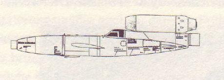
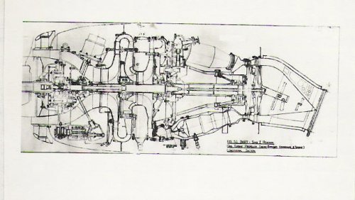
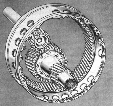
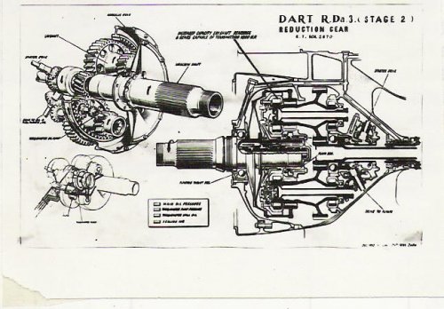
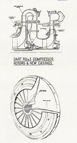
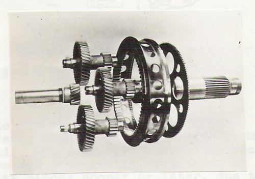
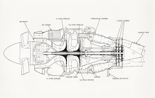
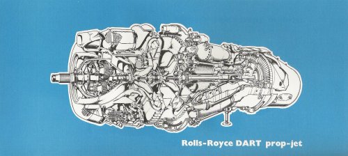
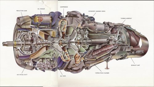
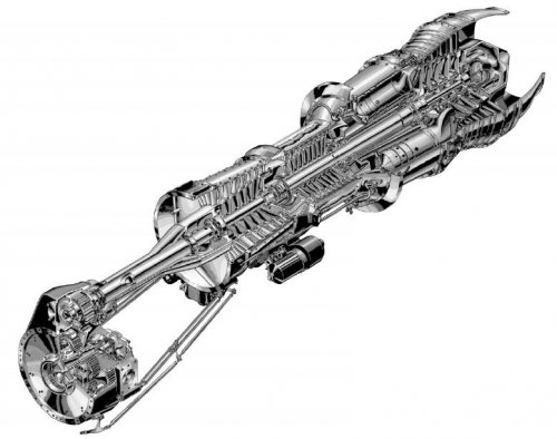
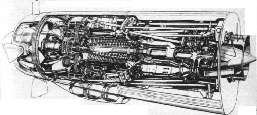
"It was natural that we chose for the compressor of the RB.53 a two-stage centrifugal type, the type which in fact we had used on later Merlin and Griffon engines. This was drawing on our previous piston engine experience; we thought that we knew something about reduction gearing since the Merlin and Griffon featured these components, but we had not attempted anything with such a large ratio as .106. The piston engine had a much smaller reduction gear ratio of .442. Having decided on the main construction of the engine, some calculations were made to determine the approximate size of the engine. In order to have 1000 hp at the propeller it was necessary to have a turbine that developed about 3000 hp driving a compressor that absorbed about 2000 hp.Thus the rough basic dimensions were arrived at. With the compressor we were hoping to use our latest knowledge and maybe a little beyond. With the turbine we decided to go beyond our jet experience and have a two-stage turbine. This engine was the first aero engine in the world to feature 2 stages in the turbine.
The engine was then sketched out to produce a design scheme with the main components worked up in enough detail for estimates of weight to be made. The project layout or scheme is then turned into a detail design and a General Arrangement generated."
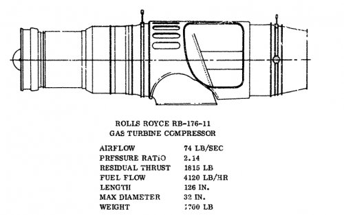
The RB 53 design project started on or around 25th April 1945 and it took 57,048 man hours over a period of 63 weeks to complete the initial design. Detail design of component parts began 12th June 1946 and took another 29,195 man hours over the next 54 weeks. First detail drawings were issued to the shops on 1st Nov 1945 and the first engine was built and ready for test by July 10th 1946.
Haworth continues:
"As soon as the engine was completely assembled, it was put on a weighing machine. Imagine how we felt when instead of showing the predicted 700 lb, the scales showed over 1100 lb! But this was not the worst blow we suffered during that second week of July, 1946; a few days later the engine was wheeled from the shops to the test bed and the anxiety as to whether it would in fact run was completely overshadowed by an inquest in the design office on the weight analysis. The engine,however, did run even under its own power, but when the next day it was decided to open up to full power we were completely stunned by the news - our 1000hp engine could only achieve a little over 600 hp. It, however, was decided to persevere with the 'heavy' engine and within a matter of a month or so it had completed a 50 hr endurance test. We were now faced with the task of finding the power and reducing the weight and these two design problems occupied us for the rest of 1946 and well into 1947.
Every piece of the engine was carefully examined to see were metal sections could be reduced or avoided all together to save weight. Magnesium was used extensively for castings instead of aluminium, and by a process of pruning every ounce of weight on desin and making certain castings were manufactured to drawing thickness (almost 100 lb of weight was put on through overthick castings) we managed to achieve a saving of some 350 lb.
The loss in power output was not really surprising on closer examination, for instead of the turbine developing 3000 hp it only achieved about 2800 hp, and instead of the compressor requiring 2000 hp it was taking over 2200 hp leaving only 600 hp for the propeller.
Another version of the RB 53 was produced which gave about 900 hp and weighed 800 lb. This engine was developed up to 1000 hp and in Aug 1947 the first 150 hr Type Test was attempted. It was not until Dec 1948 that a clear run throught the 150 hr test schedule was achieved, at a power of 1045 hp. In April 1949 a 500 hr endurance test was completed at this rating."
An aside: At some point during the War Haworth had visited Dr. R. W. Bailey at MetroVick, Manchester and had been shown a disc in the laboratory being subjected to steep radial thermal gradients by alternately heating and cooling the rim. Dr Bailey expalined he was simulating the thermal stresses that occur transiently in an engine, saying he planned to find out if the metal would attain what he called a 'cyclic state'. He further said he believed the rim hoop stress alternated between tensile and comprssion in excess of the material yield.
Haworth decided that such punishment would fail the disc and went away to find a design solution to the problem.
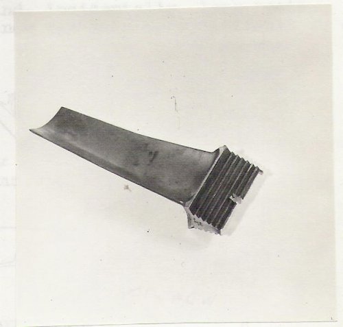
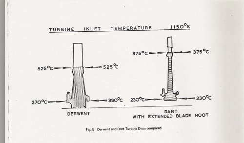
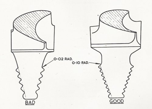
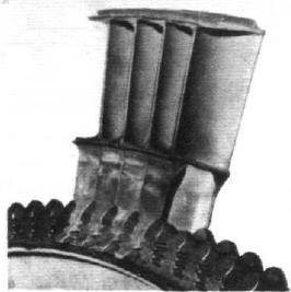
The 4th attachment below shows a crack at the bottom of the blade root slot of a Derwent engine. 13 Derwent discs failed in service from cracks like this (typical across the industry at the time). While these failures were occuring Haworth was having a design solutiion fitted to the improved RB 53 being developed. This was the extended root blade.
Back to Haworth:
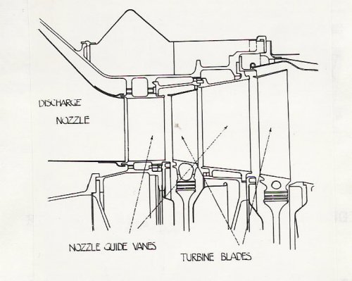
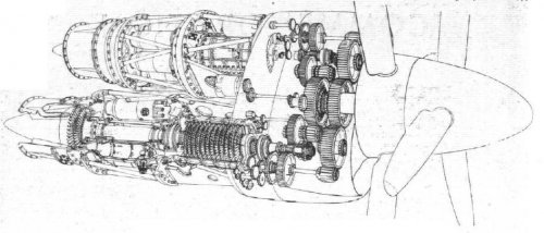
" The improved power derived from the turbine by blocking up the leaks under the NGVs prompted some thought to be put into the idea of blocking up the leaks over the top of the turbine blade.
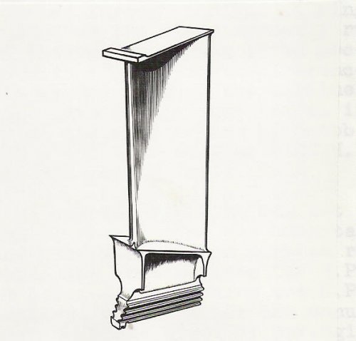
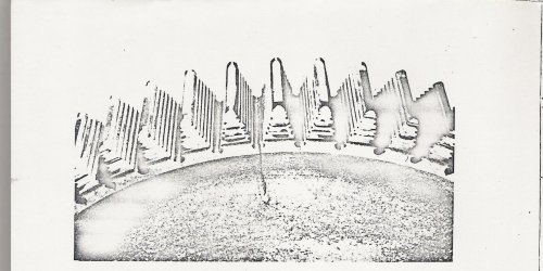
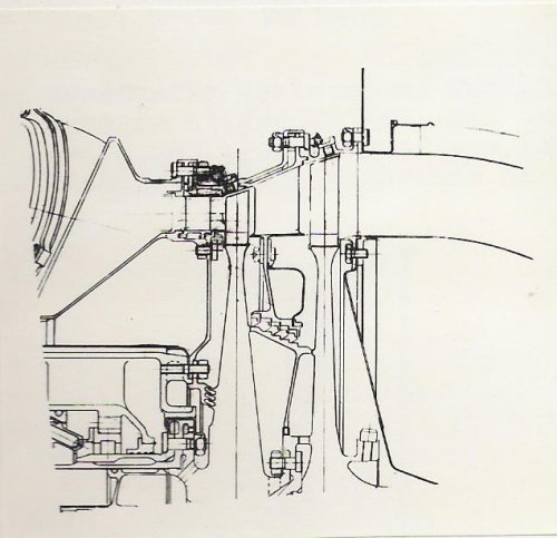
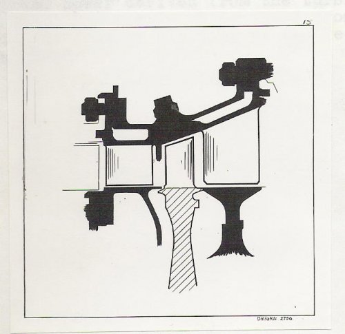
This was eventually achieved by designing a turbine blade with a shroud on it and to seal off the hot gas on the front edge of the blade by a very narrow land running against a face with as small a clearance as possible. Hence this engine was the first aero engine to have shrouded blades and, incidentally, long roots. Obtaining the correct clearance was very much more difficult to calculate and we resorted to trial and error, observing the stae of the shroud upper surface through holes in the casing. We adjusted the running clearances until we only had a slight rub.
The improved turbine design gave a substantial increase in efficiency and by Oct 1948 we were able to complete a type test at 1100 hp and an sfc of .867.
"It was natural that we chose for the compressor of the RB.53 a two-stage centrifugal type, the type which in fact we had used on later Merlin and Griffon engines. This was drawing on our previous piston engine experience; we thought that we knew something about reduction gearing since the Merlin and Griffon featured these components, but we had not attempted anything with such a large ratio as .106. The piston engine had a much smaller reduction gear ratio of .442. Having decided on the main construction of the engine, some calculations were made to determine the approximate size of the engine. In order to have 1000 hp at the propeller it was necessary to have a turbine that developed about 3000 hp driving a compressor that absorbed about 2000 hp.Thus the rough basic dimensions were arrived at. With the compressor we were hoping to use our latest knowledge and maybe a little beyond. With the turbine we decided to go beyond our jet experience and have a two-stage turbine. This engine was the first aero engine in the world to feature 2 stages in the turbine.
The engine was then sketched out to produce a design scheme with the main components worked up in enough detail for estimates of weight to be made. The project layout or scheme is then turned into a detail design and a General Arrangement generated."
The RB 53 design project started on or around 25th April 1945 and it took 57,048 man hours over a period of 63 weeks to complete the initial design. Detail design of component parts began 12th June 1946 and took another 29,195 man hours over the next 54 weeks. First detail drawings were issued to the shops on 1st Nov 1945 and the first engine was built and ready for test by July 10th 1946.
Haworth continues:
"As soon as the engine was completely assembled, it was put on a weighing machine. Imagine how we felt when instead of showing the predicted 700 lb, the scales showed over 1100 lb! But this was not the worst blow we suffered during that second week of July, 1946; a few days later the engine was wheeled from the shops to the test bed and the anxiety as to whether it would in fact run was completely overshadowed by an inquest in the design office on the weight analysis. The engine,however, did run even under its own power, but when the next day it was decided to open up to full power we were completely stunned by the news - our 1000hp engine could only achieve a little over 600 hp. It, however, was decided to persevere with the 'heavy' engine and within a matter of a month or so it had completed a 50 hr endurance test. We were now faced with the task of finding the power and reducing the weight and these two design problems occupied us for the rest of 1946 and well into 1947.
Every piece of the engine was carefully examined to see were metal sections could be reduced or avoided all together to save weight. Magnesium was used extensively for castings instead of aluminium, and by a process of pruning every ounce of weight on desin and making certain castings were manufactured to drawing thickness (almost 100 lb of weight was put on through overthick castings) we managed to achieve a saving of some 350 lb.
The loss in power output was not really surprising on closer examination, for instead of the turbine developing 3000 hp it only achieved about 2800 hp, and instead of the compressor requiring 2000 hp it was taking over 2200 hp leaving only 600 hp for the propeller.
Another version of the RB 53 was produced which gave about 900 hp and weighed 800 lb. This engine was developed up to 1000 hp and in Aug 1947 the first 150 hr Type Test was attempted. It was not until Dec 1948 that a clear run throught the 150 hr test schedule was achieved, at a power of 1045 hp. In April 1949 a 500 hr endurance test was completed at this rating."
An aside: At some point during the War Haworth had visited Dr. R. W. Bailey at MetroVick, Manchester and had been shown a disc in the laboratory being subjected to steep radial thermal gradients by alternately heating and cooling the rim. Dr Bailey expalined he was simulating the thermal stresses that occur transiently in an engine, saying he planned to find out if the metal would attain what he called a 'cyclic state'. He further said he believed the rim hoop stress alternated between tensile and comprssion in excess of the material yield.
Haworth decided that such punishment would fail the disc and went away to find a design solution to the problem.
The 4th attachment below shows a crack at the bottom of the blade root slot of a Derwent engine. 13 Derwent discs failed in service from cracks like this (typical across the industry at the time). While these failures were occuring Haworth was having a design solutiion fitted to the improved RB 53 being developed. This was the extended root blade.
Back to Haworth:
" The improved power derived from the turbine by blocking up the leaks under the NGVs prompted some thought to be put into the idea of blocking up the leaks over the top of the turbine blade.
This was eventually achieved by designing a turbine blade with a shroud on it and to seal off the hot gas on the front edge of the blade by a very narrow land running against a face with as small a clearance as possible. Hence this engine was the first aero engine to have shrouded blades and, incidentally, long roots. Obtaining the correct clearance was very much more difficult to calculate and we resorted to trial and error, observing the stae of the shroud upper surface through holes in the casing. We adjusted the running clearances until we only had a slight rub.
The improved turbine design gave a substantial increase in efficiency and by Oct 1948 we were able to complete a type test at 1100 hp and an sfc of .867.
Attachments
-
 RR-RB 53 Dart- early design scheme.jpg51 KB · Views: 109
 -
 RR-RB 53 Dart- shrouded Turbine Blsde with extended root.jpg27.1 KB · Views: 68
 -
 RR-RB 53 Dart- unshrouded Turbine Blsde.jpg32.3 KB · Views: 56
 -
 RR-RB 37 Derwent-thermal fatigue crack Aust steel T disc.jpg266.6 KB · Views: 55
 -
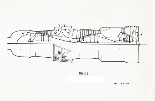
 RR-RB 53 Dart- early des scheme T Blsde and NGV.jpg54.8 KB · Views: 56
 -
 RR-RB 53 Dart- early illustration T Blsde and NGV.jpg47.1 KB · Views: 64
") . If you manage to scan your notes, they would be much appreciated as well!
. If you manage to scan your notes, they would be much appreciated as well!