On the development and variants side of things, where does the "Case X" and "Case XX" terminology come from? It is widely used in the modelling fraternity to distinguish the earlier (Case X) production wing from the later (Case XX) one with a conical-camber leading edge. But I have never seen it in any serious historical description of the "Deuce".
 
Shades of Mirage 5 for the AF models. CAS would have been difficult, but they could have been decent strike aircraft I suppose, with better range than the Mirage. Would an F-16xl type lots of little pylons approach work with either aircraft's wing?
I had a similar thought about the similarity with a hypothetical strike or ground attack F-102/106 and the Mirage 5. the Idea of adding canards for better low speed control might have worked. I am reminded of this picture (see below attachment) of a proposed "advanced F-106". I wonder if the addition of Canards and other low speed handling improvements was ever seriously considered during the F-102's service in Vietnam. Such additions might have improved the performance of Convair delta fighters in air-to-ground roles. It could be that Convair reasoned would have been too late to the party by the time they could have built a strike delta. Dassault was already working on their Mirage 5 at this time. Most likely Dassault's lead would have been too great to justify Convair spending time to build a follow on to an aircraft that was designed as an interceptor not an attacker. Especially without government funding, Convair would have been on a fool's errand in attempting to compete with Dassault. The result might not have justified the effort.

Any comments on this hypothesis would be appreciated.

Screen Shot 2022-10-31 at 1.15.23 PM.png
 
On the development and variants side of things, where does the "Case X" and "Case XX" terminology come from? It is widely used in the modelling fraternity to distinguish the earlier (Case X) production wing from the later (Case XX) one with a conical-camber leading edge. But I have never seen it in any serious historical description of the "Deuce".

Found some clues in Yenne's Convair Deltas: From SeaDart to Hustler.

Page 50 describes a "Case X wing" incorporated at the same time as the area ruling. It had a modestly cambered leading edge which was faired out in refelex fashion to avoid any camber at the tips. It is not clear from the photos whether the Case X camber was conical; one would probably have to examine a museum example close up. The YF-102A had a shorter takeoff run than the original YF-102 and better low-speed handling, and we may take it that this was at least in part thanks to the new leading edge. He mentions too that the wing was moved back and the nose lengthened, but gives no rationale for these either.

Page 62 notes that a "Case 20 wing" was introduced half way through the F-102A's production life. The text gives no further details whatsoever, but photos show that this had a more pronounced and visibly conical camber which extended right out to the tips so that they curved noticeably.

His inconsistency with the numerals at least reveals that the X and XX are ten and twenty respectively.

I have to say, there is a disappointing lack of technical detail on the aerodynamics. He does not even mention the conical form of the Case 20 camber from root to tip. What were all the other "cases" for the F-102 wings, and why this unique jargon? Then again, Chapter 1 goes at some length into the history of the thick-winged Lippisch DM-1 glider, but quite fails to mention the wartime NACA research which provided the necessary data, and led directly to the thin-wing solution actually adopted by Convair from the very start for all its deltas. Yenne offers a false impression of who Convair really owed their wing to. He was a respected writer with half a dozen books to his credit. Writing in 2009, the quality of his work should have been better than this.

Still little wiser as to what was going on.
 
Americans love to use the letter X as often as possible.
So I suspect that instead of using 'Case 1' and 'Case 2' the Convair engineers preferred to use 'Case 10' and 'Case 20' because then they could write it as 'Case X' and 'Case XX'. That does not mean that there really were 20 or more different cases of which then cases 10 and 20 were selected.

Being a delta fan I have several books on the F-102.

A quote from 'F-102 Delta Dagger in Detail and Scale Vol. 35' page 14:

"One of the more interesting changes that was made
well into the production of the F-102 was the wing change
beginning with 56-1317. The wing used up to that time
was known as the Case X (Case ten) wing, but then the
change was made to the Case XX (Case twenty) wing.
The new wing was noticeably cambered with downturned
tips. The elevons were also changed at the outer edge
where they angled outward rather than being parallel to
the aircraft's centerline. Since this wing change was
made so late in the production run, earlier aircraft were
not retrofitted. The first test aircraft with a Case XX wing
made its first flight in May 1957, and it was added to the
production line in October of that year. The ceiling
increased to 55,000 feet, maneuverability improved, and
slow speed stability was enhanced
."

Other F-102 books I have, except the Yenne book that you already mentioned, only mention X and XX. Each book does have more elaborate descriptions of the Case X and Case XX wings and fuselage modifications.
 
It's a pity the F-102s weren't retrofitted with canards like in the Mirage 50 as it would've improved its aerodynamic performance.

On another note how many F-102As converted into and expended as PQM-102A target-drones?
 
It's a pity the F-102s weren't retrofitted with canards like in the Mirage 50 as it would've improved its aerodynamic performance.
Convair did look at doing that; Yenne implies it was in 1961. By then the F-102B had long been known as the F-106A. A desktop display model of the canard version, designated 61-0630, was made but not progressed. It is worth recalling that the first production canard aircraft, the Saab Viggen, did not appear until 1967, and it also introduced the close-coupled canard to the world. The 61-0630 noticeably predates that discovery, and so would have been of limited benefit. By the time the Viggen showed the way ahead, the F-15 Eagle was being hatched.
 
Last edited:
[.......]

On another note how many F-102As converted into and expended as PQM-102A target-drones?
I am not really interested in target drones so until today I always skipped the chapter on target drones in every book I have. To answer your question I forced myself to do an effort but it turns out that the F-102 books I have are not entirely consistent in the exact numbers and types and who converted them. A summary of my quick review:

Roughly 215 airframes were converted into target drones.

The first batch were a few manned QF-102A and a few unmanned PQM-102A.
The next batch were 65 unmanned PQM-102A.
The next batch were 145 unmanned and manned improved low cost version, called PQM-102B. According to one book I have the manned version was called MPQM-102B. Not clear how many were manned.

The first (manned) QF-102A flew on 10 January 1974.
The first (unmanned) PQM-102A flew on 13 August 1974.
The last PQM-102A was probably expended in 1982, the last PQM-102B probably in 1986.
 
Last edited:
Why exactly was the conical-camber leading edge introduced? Several commentators have assumed that it would have impaired high-speed performance and so must have been done solely to help low-speed, high-AoA landings and takeoffs. Others have claimed it would have done nothing for low-speed handling and was for the high-altitude and/or transonic flight characteristics.

In Delta Wings (p.28), Mendenhall says that it was "to reduce inherent drag at high altitudes and to improve handling at the high angles of attack encountered during landing." (Yenne mentions neither the purpose of the camber nor the low-speed handling issue on the early machines).

NACA had for some years been studying the effects of conical camber on the delta wing, at both low and high speeds; to date I have noted some five papers on the subject, dating from 1947 to 1957. The last of these studies variations on an F-106 model (E.R. Phelps and J.W. Boyd, “A Wind-Tunnel Investigation of the Effects of Conical Camber for an Airplane Configuration Having a Triangular Wing of Aspect Ratio 2.2,” NACA RM A57A10, April 1957.)

When NASA revisited conical camber for their supercritical studies, in 1983 Mason wrote that "although the camber shape was developed based on supersonic flow theory, the main benefits of conical camber for drag reduction occurred at subsonic speeds." (William H. Mason; "A Wing Concept for Supersonic Maneuvering", NASA Contractor Report 3763, December 1983) Note that where Mendenhall mentions low-speed handling, Mason discusses low-speed drag.

Mason's comment harks straight back to the stable biconical delta wing discovered by British pioneer JW Dunne at the end of 1904, first published in his 1909 patent and nowadays known as the Rogallo type. But the seven papers I have found on the use of conical camber on supercrtitical wings, and its subsequent incorporation into the F-15 Eagle of quite different planform (also noted by Mason), suggest that there is more to it than that. Certainly, when the "Six" met the Navy's new F-4 Phantom II in a flyoff, it was generally able to outfly its rival and only the complex and troubled avionics systems let it down. That conical camber had to be doing something right.
 
Last edited:
Cambering the wing LE changes the flow field and increases suction at the LE which improves lift. Efficiency i.e. Lift/Drag increases for higher lift coefficients. But cambering the wing increases profile drag so it will be less efficient at lower lift coefficients.

You need different lift coefficients around the flight envelope and mission phase because it varies with speed, density and mass. Hence there are different levels of benefits at different parts of the flight envelope.

You can apply different levels of camber to optimise for different regions of the flight envelope.

Conical camber is one approach derived from classical numerical methods because it is relatively "easy" to calculate, but it doesn't give the optimum wing design. Today we have computers which makes more calculation intensive methods (e.g. Adjoint) useable where we can optimise for spanwise twist, camber, aerofoil and also include moveable LE and TE devices to allow us to better optimise performance across a range of flight conditions.

Regarding impact on handling qualities in addition to the above, this cambering is encouraging flow attachment which will improve TE control effectiveness compared to the planar wing that will separate earlier.
 
I wonder, if the bulge under the front fuselage holds an IRST (changed from in front of the canopy for the A2A-role to a much more suitable position under the front fuselage for the A2G-role), a FLIR, a laser range finder or even gun like the McDonnell F-4E Phantom II. IMHO the bulge holds some kind of a sensor than of a gun.
g in mid 1958.[...]
Sorry to reply to an old post, but on the 'F-102C' painting it looks like the Deuce in the background is firing with gun, which would seem to say that the F-102 ''ground attack'' could have received an F-4E style cannon in the bulge.
F-102C - Copie.jpg
 
Sorry to reply to an old post, but on the 'F-102C' painting it looks like the Deuce in the background is firing with gun, which would seem to say that the F-102 ''ground attack'' could have received an F-4E style cannon in the bulge.

I think not.
 
I wonder, if the bulge under the front fuselage holds an IRST (changed from in front of the canopy for the A2A-role to a much more suitable position under the front fuselage for the A2G-role), a FLIR, a laser range finder or even gun like the McDonnell F-4E Phantom II. IMHO the bulge holds some kind of a sensor than of a gun.
g in mid 1958.[...]
Sorry to reply to an old post, but on the 'F-102C' painting it looks like the Deuce in the background is firing with gun, which would seem to say that the F-102 ''ground attack'' could have received an F-4E style cannon in the bulge.
View attachment 691728
I can't tell if that's a gun or unguided rockets. if it is a gun, it would likely be similar to waht was installed on the F-106 for Project Six-Shooter.
However, the firing seems to come out of the fairing under the nose !?
But there also appears to be a flame trail behind the wing, not a smoke trail as if it were a gun. I think it shows a rocket launch.

Enjoy the Day! Mark
 
Certainly rockets, probably FFAR packs.
The undernose fairing is probably an IR track and search ball same as fitted to F-4C.
 
Certainly rockets, probably FFAR packs.
The undernose fairing is probably an IR track and search ball same as fitted to F-4C.
Almost certainly FFAR. IIRC the idea was to use the IRST to home in on VC/NVA campfires at night and fire them on the Ho Chi Min trail. Can’t remember if they ever tried it in practice, but the Deuce did get some SE Asia time.
 
C O N V A I R

F-102 Project History

In 1950, the Air Force decided it was necessary to develop a high altitude supersonic airplane and issued invitations to bid to a number of U. S. aircraft manufacturers.

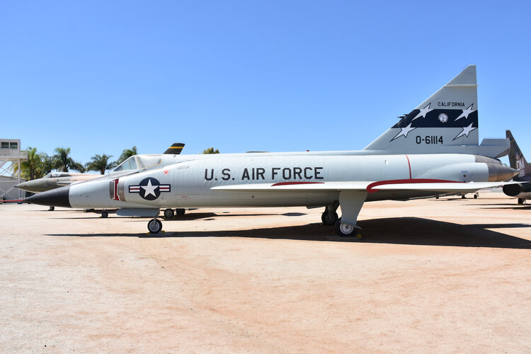
In January 1951 Convair entered the design competition by submitting its specifications on a delta wing, jet propelled aircraft which is now known as F-102A.

Convair, whose design was deemed the most desirable for the F-102 Project, was selected to carry out phase I of the development program.

In August of 1951, Convair entered into a contract for the F-102 and a letter of contract was received.

The Air Force established a new plan for the flight test development of new airplanes such as the F-102. This plan was identified as the Accelerated Develop ment Test Program and called for the use of the two prototype models and the first 40 production models to carry out all phases of development testing which had heretofore been carried out by a maximum of 6 airplanes on most test programs. This new approach to flight testing was caused primarily by the facts that, (a) The advent of supersonic flight required an almost total reinvestigation of all established flight criteria, and (b) The Accelerated Development Test Program plan shortened the development of a new airplane by a substantial period of time, thereby making new airplanes available to the defense system at an earlier date.
The tooling plan set forth by the Air Force called for tooling to produce ten airplanes per month, but that this tooling be of a type and quality for efficient production of fifty airplanes per month. A Convair counter proposal was submitted which called for a progressive tooling policy since it was realized that the Air Force intended to ultimately expand the tooling to accomodate a production rate of 50 airplanes per month and higher. This tooling policy was based on using the actual production rate of 3 airplanes per month, but of a type of tooling based on a maximum rate of 125 per month. Negotiations for a facility site were completed and the acquisition of Plant II obtained.

Some of the Engineering problems involved included the development of a newly designed aircraft around a new engine that was still in the design stage.

Planning and Tooling peculiarities involved in the production of this high speed aircraft involved the aerodynamics surface tolerances and contour control requirements which are inherent to supersonic aircraft.

Generally accepted surface irregularities as found in conventional aircraft were prohibitive in the F-102 airplane.

The advent of supersonic flight introduced many problems relative to the design of supersonic vehicles, and, since a great deal of the design criteria for super sonic vehicles was based upon theory and calculation with no specific flight experience to substantiate the theory, it has been necessary for both industry and the Air Force and Navy to revise their approach to various aircraft designs from time to time as the state of the art progresses. In this connection, a joint decision on the part of the Air Force and Convair was made to introduce a modified F-102 fuselage, wing tips and wing leading edges as a result of the gradually expanding learning curve relative to supersonic flight, which was constantly being expanded as a result of the national and international effort being made to over come the obstacles leading to general standardization of aircraft design for supersonic flight.

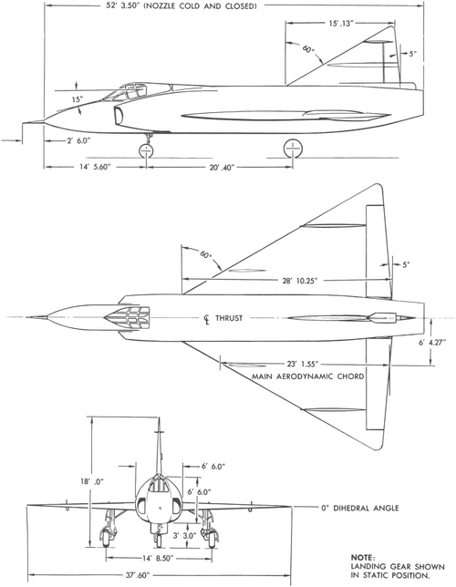
As the results became known of the tests conducted of pre-flight models in the transonic and supersonic ranges in June of 1952 by NACA (National Advisory Committee on Aeronautics) at Langley Field in Virginia, Convair pre-design Engineers felt that the theory of cross sectional area versus fuselage length had a great amount of practical application in a redesign of the then present 8-82
configuration.

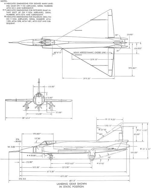
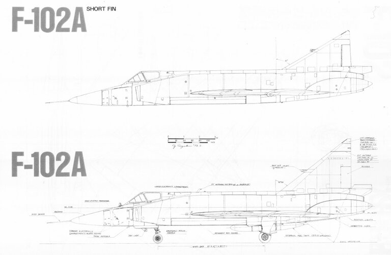
With the completion of the first HARD model tests as well as more complete tunnel tests initiated in the interests of drag reduction, it became apparent that the then present fuselage configuration drag could be reduced appreciably by incorporating a "Waisted" body idealized from the "Area-Rule Concept". This established an improved configuration involving an approximate 7 foot extension to the rear end of the fuselage with a corresponding movement of the vertical tail, and an approximate 39 inch aft movement of the wing to maintain balance. The performance gains with the J-57 engine in the transonic speed range and in high speed at altitude were sufficient to warrant serious consideration of a change in the F-102 configuration as early in the production program as was feasible. Since this change would have appreciable effect on the Flight Test program as well as upon production schedule, this subject was reviewed with all affected Air Force agencies in an effort to obtain a decision as to whether this change should be incorporated in the F-102 airplanes. It was decided that this change, despite its possible effect on production rate in the early months of its incorporation, would not have any adverse effect on the then present concept of tactical operating groups in early 1956. Although this change was of a major nature in view of the configuration changes involved, it had been established through predesign that development of the Fire Control System as well as other functional systems of the airplane would not be jeopardized since the performance and aerodynamic characteristics of the two configurations were sufficiently similar in design.

Management decision to convert to the " Ideal Body" was formulated in August of 1953, (Sales Order 33-l-S2A) and preliminary design was completed, incorporating integral ducts of which a portion would be suitable for J-57 , J-67 or J-75 engines.

Construction of the 1/9 scale flutter models were completed in October of 1953 and changes were incorporated to determine the effect of cambered leading edges and reflex tips . The first configurations had boundry layer bridging across two ramps, causing unpredifcted shock patterns with a strong vortex sheet entering the inlet . The resulting pressure recovery was considerably low er than predicted.
Replacement of the precompression ramp eliminated this bridging and with this configuration the pressure recovery approached the estimated value within 2%.

Testing was now complete.

A CCN (N-93912) was received in late October of 1953.

Preliminary design for the incorporation of the production design started in late August of 1953.

Due to the short span of time established for delivery of this redesigned airplane (December 1954), special expediting of the whole program had to be planned.

On-Board Planning was established to maintain contact with all Engineering groups for the purpose of obtaining advance in formation of changes.

Tool Design was to use and rework as many of the existing tools and fixtures as were feasible .

Production shops were to work to a condensed schedule build in g sub-assemblies in to larger components or directly in to the airplane .

Special expedite action had to be established on outside purchased parts that were long lead time development items.

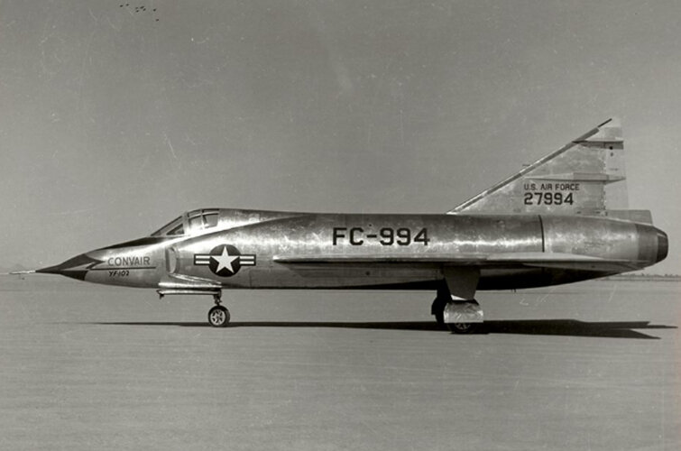
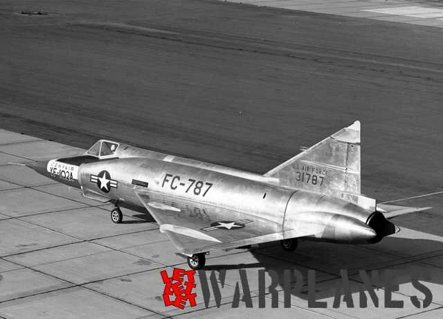
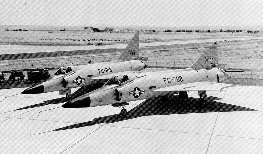
Detail design for the #1 prototype was started in April of 1952 and completed in April of 1953. Fabrication and assem bly were s ta r te d in July of 1952 and the #1 prototype airplane was completed in October of 1953 and shipped to Edwards Air Force Base a t Muroc, California.

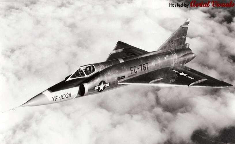
Flight testing reached six flights during October. The quality of the airplane handling characteristics and performance follow ed close to predicted figures . On November 2, 1953, the airplane was lost during a take-off on Flight #7.

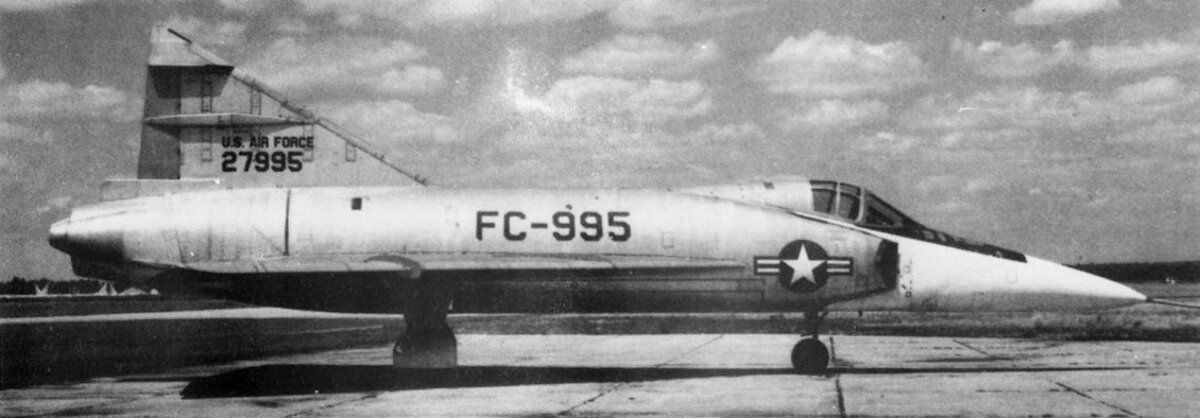
The #2 prototype at this time was well along in production . This was rushed to completion and delivered to Edwards Air Force Base on the 14th of December, 1953.

The first high speed taxi tests and a half mile lift off was accomplished on 31 December 1953. The initial flights that followed after the first of the year 1954 consisted primarily of successive incremental increases in speed as permitted by in flight flutter vibration tests.
The airplane was grounded after Flight #9 due to malfunction of the engine and to rework the air in take ducts.

This work, is now in process and nearing completion. Flight testing is scheduled to resume on the weekend of 28 February.

Present Status

Of approximately 568 EWO’s on the new body configuration , 149 have been final released as of this date . This amounts to approximately 25% of the total design release on the new body style.

On-Board Planning has written and issued tool orders in the amount of 5502.
Production orders now in the system peculiar to the 8-90 model amount to 1924.

Nice 1954 Convair document on F-102 development.
 

Attachments

  • F-102 Project History.pdf
    2.2 MB · Views: 56
F-102A and F-106 Interceptor Bombers (Convair Report ZP-8-062 from SDASM collection)
 

Attachments

  • F-102 Part 9 - F106-F102 DS_text - 0116.jpg
    F-102 Part 9 - F106-F102 DS_text - 0116.jpg
    228.8 KB · Views: 65
  • F-102 Part 9 - F106-F102 DS_text - 0115.jpg
    F-102 Part 9 - F106-F102 DS_text - 0115.jpg
    394.9 KB · Views: 56
  • F-102 Part 9 - F106-F102 DS_text - 0114.jpg
    F-102 Part 9 - F106-F102 DS_text - 0114.jpg
    259.6 KB · Views: 57
  • F-102 Part 9 - F106-F102 DS_text - 0113.jpg
    F-102 Part 9 - F106-F102 DS_text - 0113.jpg
    284.5 KB · Views: 57
  • F-102 Part 9 - F106-F102 DS_text - 0112.jpg
    F-102 Part 9 - F106-F102 DS_text - 0112.jpg
    302.4 KB · Views: 80
  • F-102 Part 9 - F106-F102 DS_text - 0111.jpg
    F-102 Part 9 - F106-F102 DS_text - 0111.jpg
    376.7 KB · Views: 95
  • F-102 Part 9 - F106-F102 DS_text - 0110.jpg
    F-102 Part 9 - F106-F102 DS_text - 0110.jpg
    430.7 KB · Views: 101
  • F-102 Part 9 - F106-F102 DS_text - 0107.jpg
    F-102 Part 9 - F106-F102 DS_text - 0107.jpg
    587.9 KB · Views: 88
  • F-102 Part 9 - F106-F102 DS_text - 0106.jpg
    F-102 Part 9 - F106-F102 DS_text - 0106.jpg
    1.1 MB · Views: 88
F-102A with external 'Ding Dong' missile (Convair Report ZP-8-023 from SDASM collection)
 

Attachments

  • F-102 Part 9 - F106-F102 DS_text - 0147.jpg
    F-102 Part 9 - F106-F102 DS_text - 0147.jpg
    279.8 KB · Views: 91
  • F-102 Part 9 - F106-F102 DS_text - 0148.jpg
    F-102 Part 9 - F106-F102 DS_text - 0148.jpg
    297.5 KB · Views: 88
  • F-102 Part 9 - F106-F102 DS_text - 0149.jpg
    F-102 Part 9 - F106-F102 DS_text - 0149.jpg
    391.8 KB · Views: 88
From Mr. Tony Buttler.

An F-102 with one let alone two J-79s would've had some serious specific excess thrust to maneouvre with.
J57-P-25 (1955) of F-102A/TF-102A produced 11,700 lb.s.t. (17,200 lb.s.t. afterburning).

J79-GE-15 (1959) of F-4B/C/D produced 10,900 lb.s.t. (17,000 lb.s.t. afterburning).
J79-GE-17 (1966) of F-104S produced 11,430 lb.s.t. (17,860 lb.s.t. afterburning) [most powerful J79 before the J79-119 of 1980].
Earlier J79s were in the 10,000/16,000 range.

So one J79 would be virtually identical in thrust or a touch LESS.
 
www.forgottenjets.warbirdsresourcegroup.org/F-102A.html

I was wondering about all the flawed YF-102s that were good for nothing. What does "struck off charge" and "salvaged" means exactly ? did those planes ever flew ? or were they just stored on the ground ?
“Struck off charge” means that it was removed from inventory lists and warehouses. Rarely, it would auctioned off as military surplus, it more likely it was stripped of any re-useable parts (radios and engines) then sold to a scrap metal dealer who promptly cut it into small pieces to be recycled.
“Salvaged” means that the USAF salvaged …. er …. removed and refurbished any reusable radios or engines, then the USAF cut it up for scrap metal. That scrap metal was auctioned off to metal recyclers and converted into soda pop cans.
 
Last edited:
Seems most of them never flew but went directly into storage, either at Convair(San Diego) or at Norton AFB. I already heard about the latter: this is the place were decommissioned 1st gen ICBMs (Atlas F & Titan I) went after decommissioning in 1966.
 

Similar threads

Back
Top Bottom