blackkite
Don't laugh, don't cry, don't even curse, but.....
- Joined
- 31 May 2007
- Messages
- 9,408
- Reaction score
- 9,272
Hi!
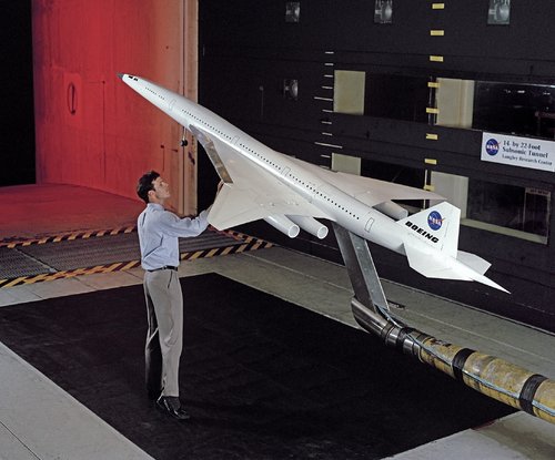
The Evolution of the High-Speed Civil Transport. No information about Republic proposal.
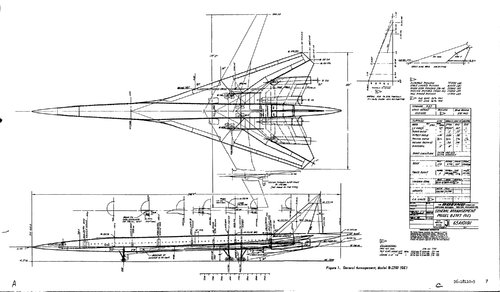
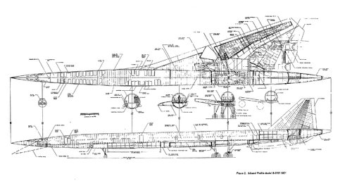
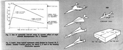
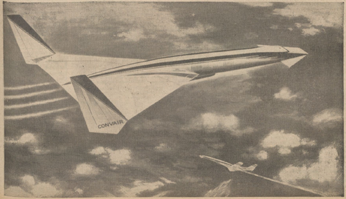
Also Convair 1961 SST information is here.
The Evolution of the High-Speed Civil Transport. No information about Republic proposal.
Also Convair 1961 SST information is here.
Attachments
-
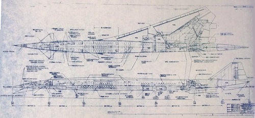
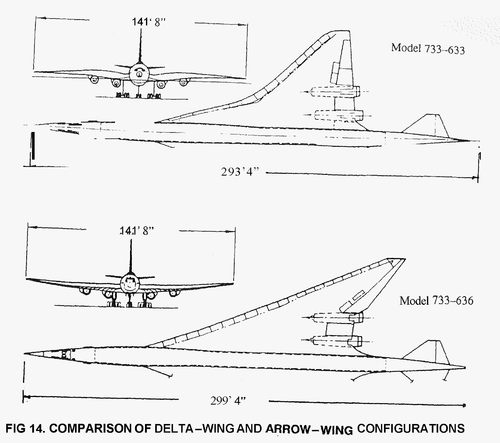
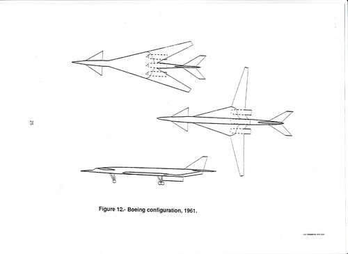 boeing configulation 1961.jpg85.8 KB · Views: 153
 -
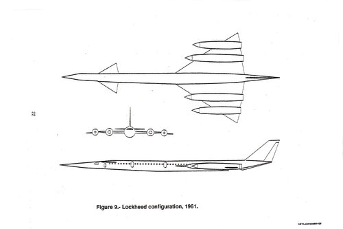 Lockheed configulation 1961.jpg80 KB · Views: 153
 -
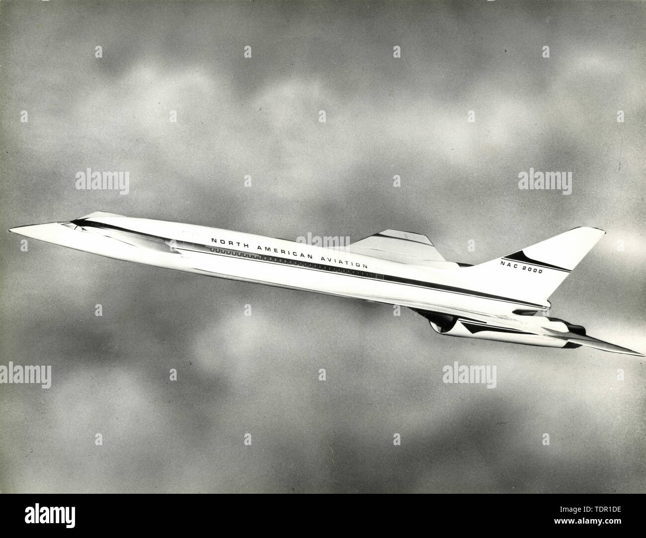
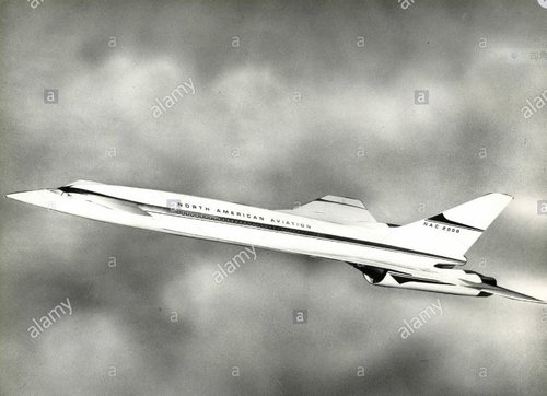
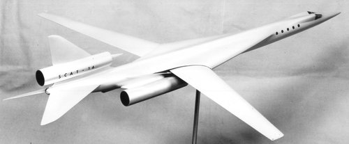
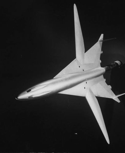
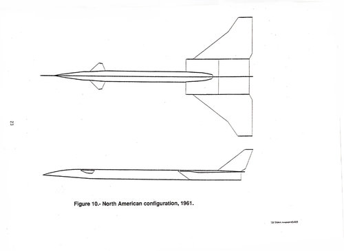 North American configulation 1961.jpg65.6 KB · Views: 146
 -
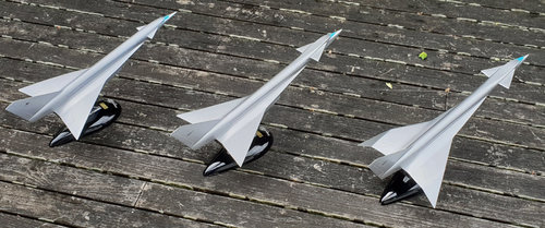
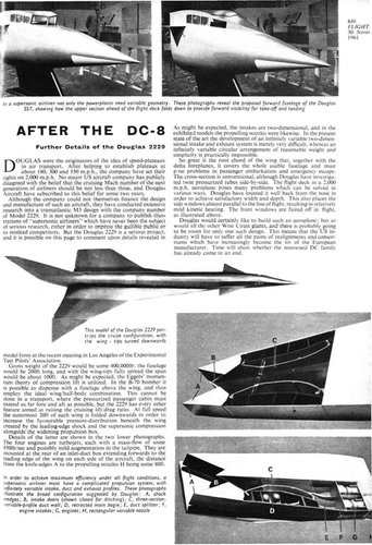
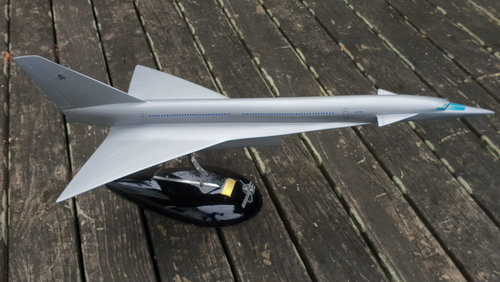
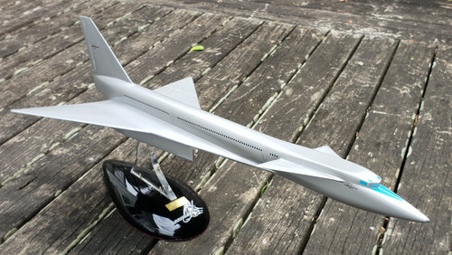
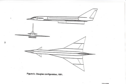 Douglas configulation 1961.jpg90 KB · Views: 135
 -
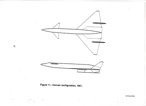 Convair configulation 1961.jpg71 KB · Views: 140
 -
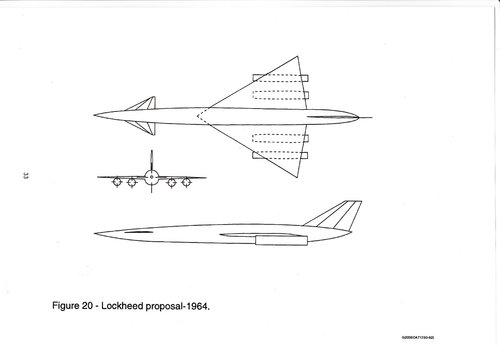 Lockheed proposal 1964.jpg78.3 KB · Views: 143
 -
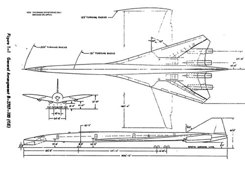
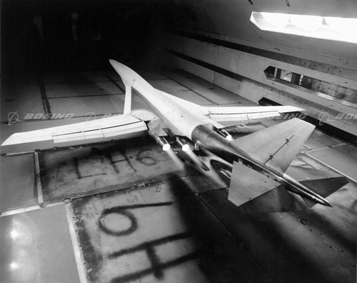
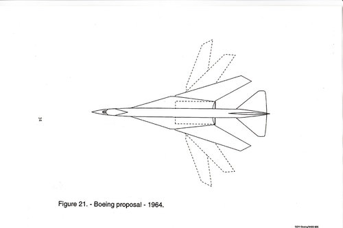 Boeing proposal 1964.jpg70.6 KB · Views: 173
Last edited:


") ) keep posting stuff in this monster thread, but if modos find it inapropriate i'll stop. For sure the thread is a wealth of infos on the SST, excellent reference, but it's also getting difficult to follow due to size and images posted 2 or even 3 times in the thread (my bad too...).
) keep posting stuff in this monster thread, but if modos find it inapropriate i'll stop. For sure the thread is a wealth of infos on the SST, excellent reference, but it's also getting difficult to follow due to size and images posted 2 or even 3 times in the thread (my bad too...).


![Les_Ailes___journal_hebdomadaire_[...]_bpt6k3201019g_3.jpeg](/data/attachments/154/154511-2c7728d772d7cb8081870a6956046438.jpg)