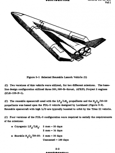
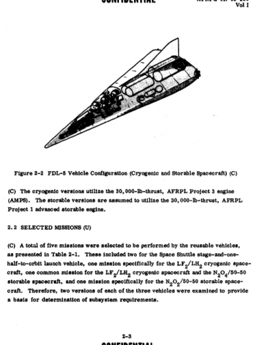
Desert Dawn
ACCESS: Confidential
XP67_Moonbat said:Folks,
Looks like PlanetSpace is making some moves. Be interesting to see to how far they can keep it going with their effort. And it's always nice to see an FDL shape take flight.
http://www.planetspace.org/lo/index.htm
Moonbat
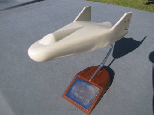
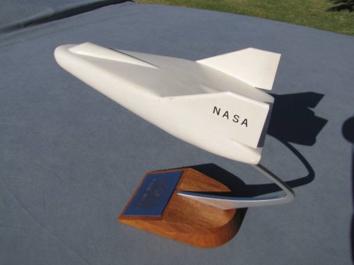
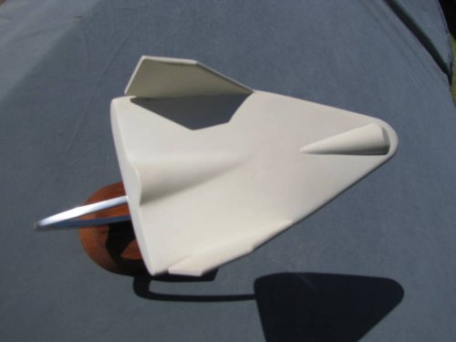
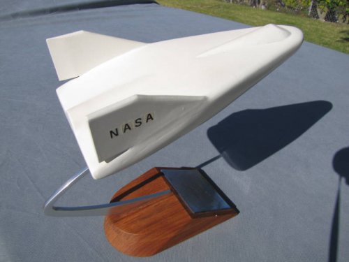
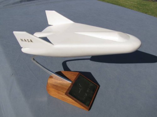
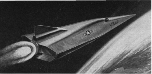
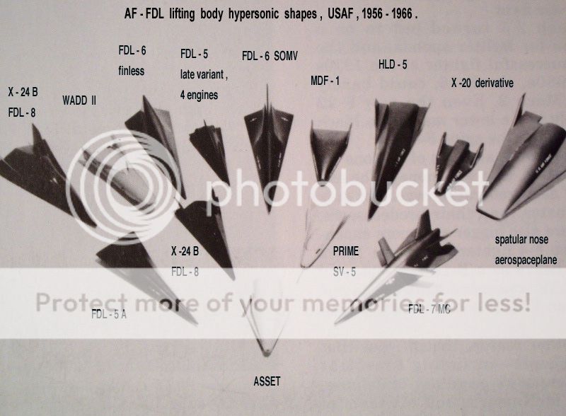
The problem with trying to build and fly a 40 plus years old FDL-7 derivative design for paying space tourists is that it is akin to aeronautical archeology.
Imagine if people had decided to fly a replica of the Wright Brothers aircraft in the 1950`s and presented it like `cutting edge` technology or a `good business plan` and had flown it for paying customers. That would have been called non-sense.
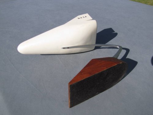
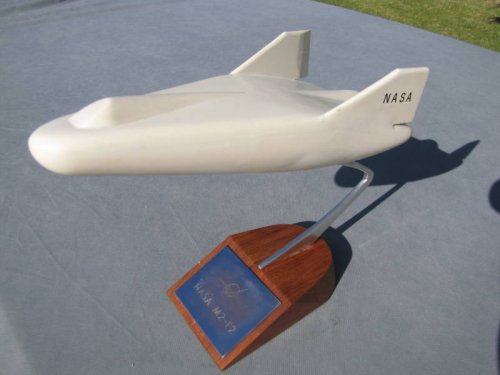
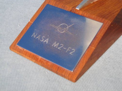
They have also only met the first 5 Nasa milestones that were requested from them if they wanted their spaceplane to be accepted for transport to the ISS (a competition they now lost) : They only made it to the wood mock-up stage with truck tires taken from the local dump.. While there were at least 30 Nasa milestones to meet (including of course cutting metal and making the actual super alloy skin and structures, and test flights (several of those). Needless to say, they never made a single part that i know of for the full-size vehicle project. And now they are going to fly 1/4 size R/C models... (why...? It`s been all done by Dale Reed in the 60`s...). Well.. I have my little idea about this, and it is not the one you think.
Although we have yet to see spaceplanes fly with cooled or insulated metallic skin protection, the cutting edge today for space tourism airplanes are Burt Rutan`s SpaceShip One and SpaceShip Two. You build you spaceplane with modern materials (carbon fiber), your assembly and building are ULTRA simple (you just TAPE the whole thing together (!!), molds are very easy to make (no expensive, very complex stiffened metal panels, no complicated internal cooling channels and retainer clips), the heat shield is jokingly simple (and high tech too: an ablative coating made with silk from a South America spider, which works)(unlike the old X-15 ablative system), an innovative hybrid rocket system and simple ablative rocket nozzle, and a truly revolutionnary aerodynamic system for a low temperature reentry, safe and simple. Pure genius.
Now i can`t wait to see what Burt will come up with when they will make the boost-glide version of their SpaceShip Two.

")