i that case i recommend to look into turret of "Schützenpanzers (kurz) Hotchkiss"
I’ve been working on that for some time. Bought several books covering the SPz11-2, SPz12-3 and Marder. The lack of published plans / drawings / blueprints on these vehicles is frustrating. Especially the Hispano-Suiza vehicles.
I have partially constructed a scale drawing of the HS30 turret, but very difficult. I have found useful photos of wrecks / restoration work showing the turret hole in the hull and the turret, but lack dimensions. I really want a cross-section through the turret (front to back) showing the HS820, seat and other internal details. I suppose the Bundesarchive might have something. I’m not able to travel, so that would have to wait for someone else to visit.
I have found some drawings of the SPz11-2, however, the turret is not exactly the same as the HS30 (SPz12-3).
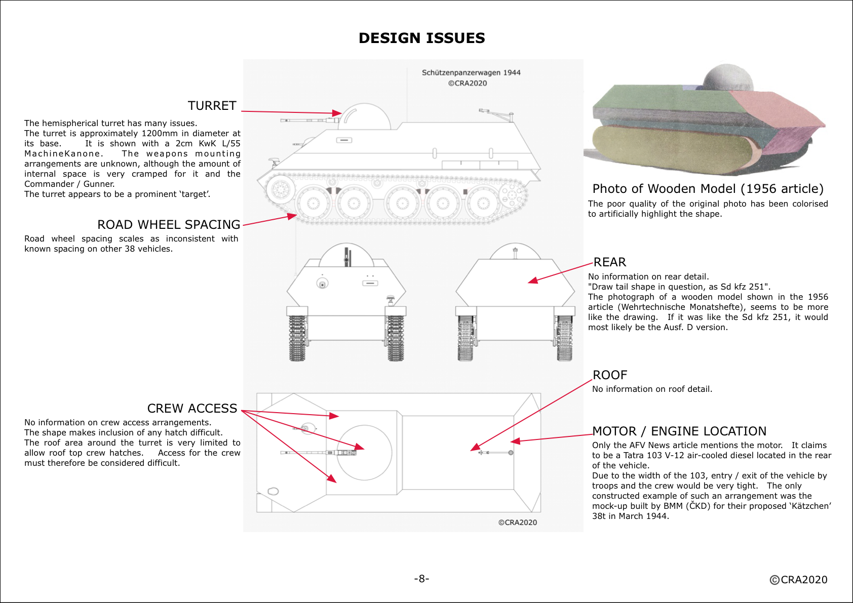
on Roof and back door on that Wood model
the german text describe the requirement of ABC protection for the Crew and soldiers onboard
This imply that must be a enclosed roof.
Yes, absolutely. The author was thinkng of nuclear war - a recent concern for the time.
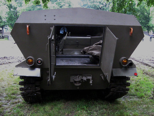
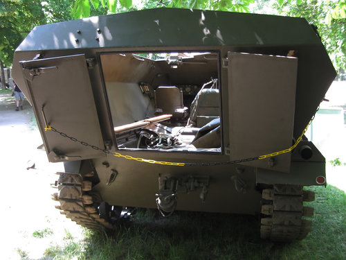
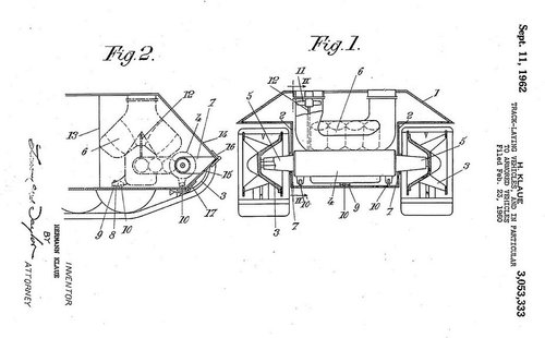
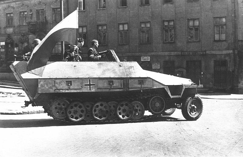
on back door from the form of the rear end, it look almost of the "Schützenpanzerwagen Sd.Kfz. 251"
then would look the door like that (right side)
Oddly the german text, explain that the 1956 proposal has to be build simpel and easy.
what is in-contradiction with wood Model
in fact the later generation of Sd.Kfz. 251 had simplified flat rear and simpler Doors.