
You are using an out of date browser. It may not display this or other websites correctly.
You should upgrade or use an alternative browser.
You should upgrade or use an alternative browser.
McDonnell-Douglas Model 260 VSTOL project
- Thread starter Antonio
- Start date
- Joined
- 22 January 2006
- Messages
- 4,213
- Reaction score
- 2,010

- Joined
- 27 December 2005
- Messages
- 17,748
- Reaction score
- 26,408
Moved to own topic
- Joined
- 27 December 2005
- Messages
- 17,748
- Reaction score
- 26,408
- Joined
- 27 December 2005
- Messages
- 17,748
- Reaction score
- 26,408
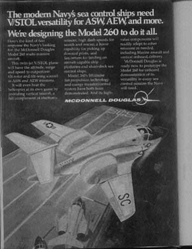
4.1.5 McDonnell Douglas
Over the past 10 yr or so, the McDonnell Aircraft Company (MCAIR) has conducted studies of medium-speed V/STOL utility aircraft. Candidate concepts included gas and mechanically coupled lift-fan aircraft. A number of these concepts were wind-tunnel-tested. Parallel to this lift-fan activity, MCAIR conducted the AV-8B program and gained valuable experience in the design of vectored thrust concepts. This experience was recently (1980) applied to the design of another medium-speed concept featuring a "two-poster" propulsive lift system. All of these concepts are briefly described in the following paragraphs.
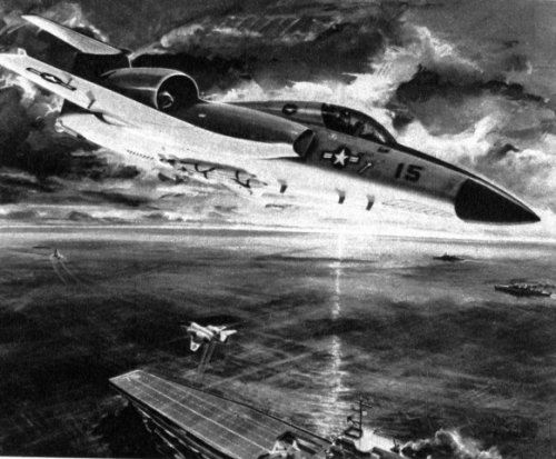
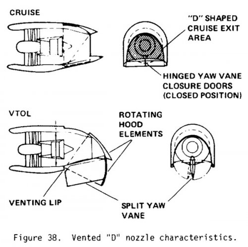
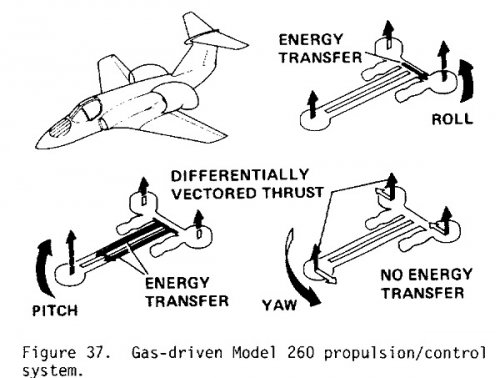
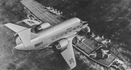
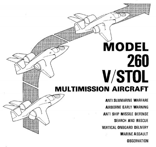
The first concept, proposed in 1973 for Navy consideration, was a gas-driven aircraft (Model 260) utilizing a three-fan, lift plus lift/cruise propulsion system. Figure 36 is an artist's rendering of the MCAIR gas-driven version of the 260 design. The propulsion and vertical-flight-control system are illustrated in Fig. 37. In this system, pitch and roll control are accomplished via energy transfer between the fan assemblies, and yaw control is achieved through differential thrust vectoring. Thrust vectoring of the lift/cruise engines is provided by means of a MCAIR-developed vented "D" nozzle (Ref. 21). Figure 38 illustrates the characteristics of this nozzle in both the cruise and VTOL modes. The nozzle consists of movable deflector hoods and a split yaw vane/closure door assembly attached to a single support beam centrally located on the bottom of the nozzle structure. In the cruise mode, the yaw vane doors are closed to form a flat bottom duct and a "D" shaped exit area (Fig. 38). For transition to vertical flight, the closure doors are each rotated 90° to form a single split-yaw vane. Longitudinal thrust vectoring is then accomplished by rotation of the deflector hood elements. Lateral vectoring is obtained by deflection of the split-yaw vane.
The "0" nozzle utilizes a concept referred to as "venting." This is accomplished by removing the inside wall of the elbow turn of a conventional deflector nozzle design, which has been shown to improve the 90° vectoring performance (Ref. 22). The performance characteristics of the "D" vented nozzle was demonstrated in a NASA Ames/MCAIR test program (1981) using a TF34 engine. The results are discussed in Refs. 22 and 23.
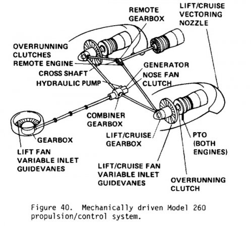
In 1977 MCAIR proposed a mechanically driven version of the Model 260 to the Navy. This concept is shown in Fig. 39. The baseline aircraft featured a low wing, three engines, and a mechanically driven three-fan arrangement. This propulsion and vertical-flight-control concept is illustrated in Fig. 40. The third engine, mounted forward of the vertical fin, is used only during V/STOL operation. All jet-borne aircraft control is provided by differential operation and deflection of the propulsion system, eliminating the need for a separate reaction-control system. All three fans and turboshaft engines are identical, minimizing development and maintenance costs. Lift/cruise thrust from each of the direct-drive, wing-mounted fan/engine assemblies is provided via the "D" vented nozzle.
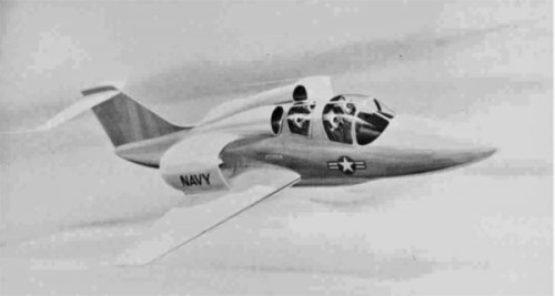
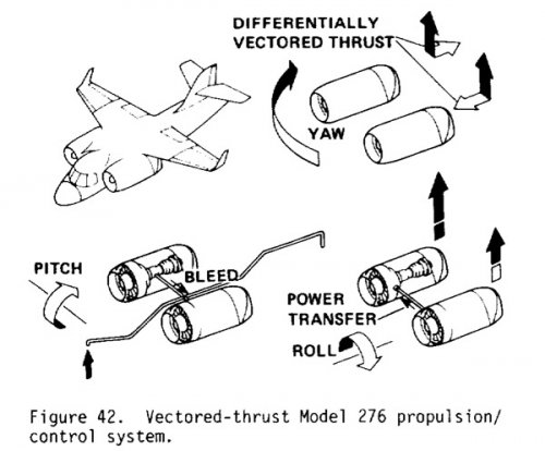
In 1980 MCAIR initiated definition of a twin-engine vectored-thrust concept with a simpler propulsion system than the three-fan Model 260 concept. This concept is designated Model 276 and is depicted by the artist's rendering in Fig. 41 and discussed in Ref. 24. The Model 276 is a high wing design with two shoulder mounted high by-pass turbofan engines. As shown in Fig. 42, attitude control in powered-lift flight is provided by an engine-bleed reaction-control system in pitch, differential thrust modulation in roll, and differential thrust vectoring in yaw. Power transfer between engines by means of cross shafting permits a wide range of thrust modulation for roll control, including engine-out balance capability. A technology demonstrator of this concept using two "0" vented nozzles and TF34 engines has been defined. Mission performance characteristics of the Model 276 aircraft are discussed in Ref. 24.
Attachments
- Joined
- 27 December 2005
- Messages
- 17,748
- Reaction score
- 26,408
- Joined
- 27 December 2005
- Messages
- 17,748
- Reaction score
- 26,408
Another NASA report.
- Joined
- 11 March 2006
- Messages
- 8,625
- Reaction score
- 3,804
- Joined
- 26 May 2006
- Messages
- 34,895
- Reaction score
- 15,759
- Joined
- 26 May 2006
- Messages
- 34,895
- Reaction score
- 15,759


- Joined
- 31 May 2009
- Messages
- 1,154
- Reaction score
- 674
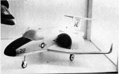
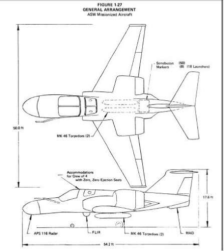
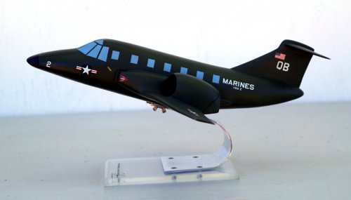
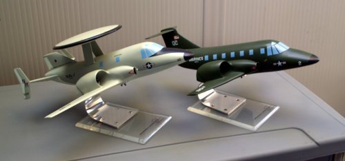
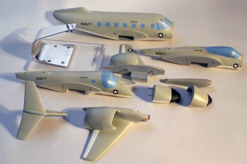
Attached is a photo of the seldom-seen McAir 260 ASW variant, next to the COD variant in USMC colors. I'm not too familiar with the structure of McDonnell / McAir as an organization, but they appeared to remain independent of McDonnell Douglas (MDC) for many years after the 1967 merger.
Attachments
- Joined
- 13 June 2007
- Messages
- 2,173
- Reaction score
- 3,093
Nice models - thanks!
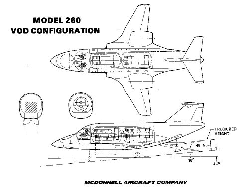
Will be posting some drawings from a McAir document on the Model 260 which is in the possession of the Greater St. Louis Aviation Museum shortly.
Enjoy the Day! Mark
Will be posting some drawings from a McAir document on the Model 260 which is in the possession of the Greater St. Louis Aviation Museum shortly.
Enjoy the Day! Mark
- Joined
- 13 June 2007
- Messages
- 2,173
- Reaction score
- 3,093
Greetings All -
Got the drawings in the report scanned today - here you go....
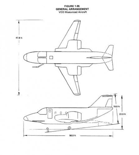
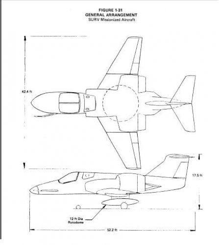
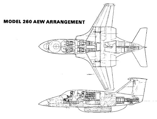
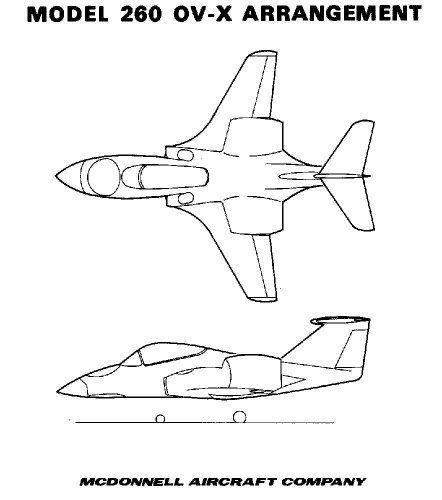
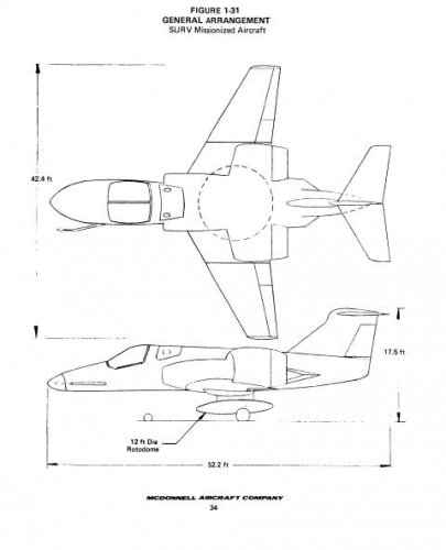
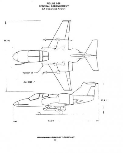
Interesting that the AEW drawing shows an underside radome vs. the model's upper rotodome set up. The OV-X derivative is interesting too.
Enjoy the Day! Mark
Got the drawings in the report scanned today - here you go....
Interesting that the AEW drawing shows an underside radome vs. the model's upper rotodome set up. The OV-X derivative is interesting too.
Enjoy the Day! Mark
Attachments
-
 xModel 260 AEW Arrangement.jpg112.1 KB · Views: 372
 -
 xModel 260 ASW Inboard Profile.jpg263.2 KB · Views: 346
 -
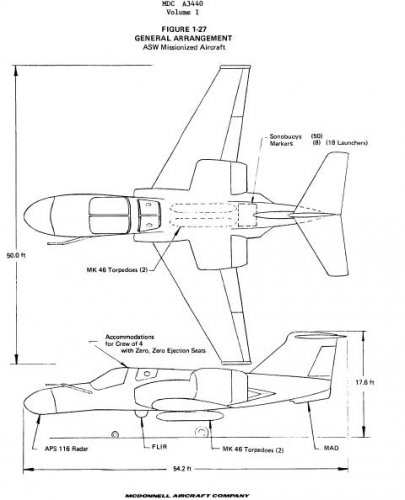
 xModel 260 General Arrangement.jpg91.3 KB · Views: 294
 -
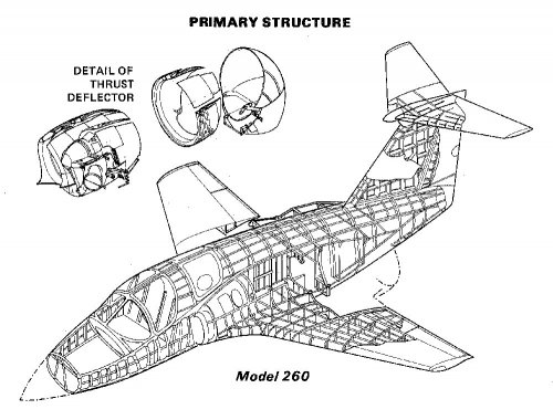 xModel 260 Primary Structure.jpg154 KB · Views: 278
 -
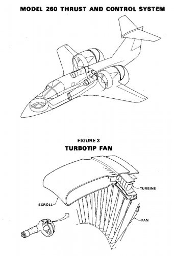 xModel 260 Thrust and Control System.jpg115.7 KB · Views: 260
 -
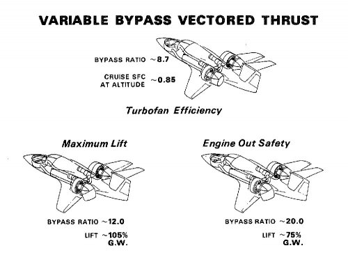 xModel 260 Variable Bypass Vectored Thrust.jpg99 KB · Views: 272
 -
 xModel 260 Model Adaption.jpg84.8 KB · Views: 245
 -
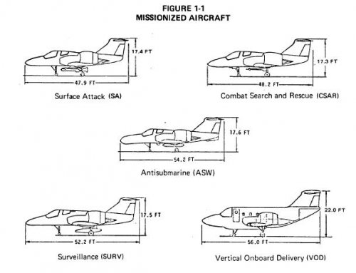
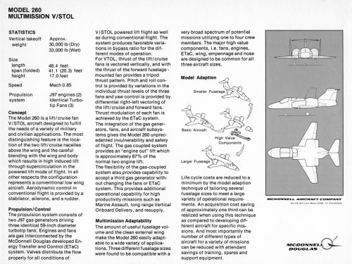
 xModel 260 VSTOL Multimission Aircraft.jpg156.4 KB · Views: 221
- Joined
- 13 June 2007
- Messages
- 2,173
- Reaction score
- 3,093
... and a few more...
Attachments
- Joined
- 18 March 2008
- Messages
- 3,529
- Reaction score
- 978
circle-5 said:I'm not too familiar with the structure of McDonnell / McAir as an organization, but they appeared to remain independent of McDonnell Douglas (MDC) for many years after the 1967 merger.
'McAir' was the US Navy's abbreviation for McDonnell Aircraft Corporation. After the merger with Douglas Aircraft Company the new McDonnell Douglas Corporation (MDC) retained separate aircraft divisions with McDonnell Aircraft in St.Louis and Douglas Aircraft in Long Beach. The US Navy kept writing MDC aircraft from St. Louis as "McAir" aircraft on their paperwork (F-18, A-12).
- Joined
- 2 August 2006
- Messages
- 3,255
- Reaction score
- 1,527
Wow, that's an awesome report Mark! I have some more stuff I'll be posting this summer, not related to this program, but other design studies. I'm in the process of moving and it's great having access to a bunch of stuff I haven't seen in years. ")
Once I'm moved and have my new PC up and running and the scanner hooked up, I'll get some more cool drawings posted here. Nothing as good as what Mark has been posting lately, but stuff you guys will enjoy.
Once I'm moved and have my new PC up and running and the scanner hooked up, I'll get some more cool drawings posted here. Nothing as good as what Mark has been posting lately, but stuff you guys will enjoy.
- Joined
- 31 May 2009
- Messages
- 1,154
- Reaction score
- 674
Abraham, thank you for the clarification and Mark, thank you for the great set of drawings. I have another factory model of the McAir 260, with an extra gas generator on top. I'll post a couple pictures after I dig it out of storage.Abraham Gubler said:'McAir' was the US Navy's abbreviation for McDonnell Aircraft Corporation. After the merger with Douglas Aircraft Company the new McDonnell Douglas Corporation (MDC) retained separate aircraft divisions with McDonnell Aircraft in St.Louis and Douglas Aircraft in Long Beach. The US Navy kept writing MDC aircraft from St. Louis as "McAir" aircraft on their paperwork (F-18, A-12).
- Joined
- 18 March 2008
- Messages
- 3,529
- Reaction score
- 978
Mark Nankivil said:Interesting that the AEW drawing shows an underside radome vs. the model's upper rotodome set up. The OV-X derivative is interesting too.
From the 1976 NASA paper posted above by Hesham the underside radar (an extendable 12' rotordome) was chosen over the more conventional upper radar because it enabled the retention of a common T-Tail and fuselage (it attached to the common central stores pylon). Also since the MDC 260 SURV (AEW) aircraft would loiter at 35,000 feet the field of regard of the radar did not suffer thanks to the underside configuration, without any aircraft structure in the way it would be better.
Be interesting to see the relationship between Mark's pictures and the NASA report. I suspect the pictures may be a later design study.
With a top speed of Mach 0.8 up to and over 40,000 feet and 5 G maneuver one of these aircraft would make a respectable fighter...
- Joined
- 18 March 2008
- Messages
- 3,529
- Reaction score
- 978
LF460 Lift Fan paper
http://ntrs.nasa.gov/archive/nasa/casi.ntrs.nasa.gov/19730012338_1973012338.pdf
http://ntrs.nasa.gov/archive/nasa/casi.ntrs.nasa.gov/19730012338_1973012338.pdf
- Joined
- 13 June 2007
- Messages
- 2,173
- Reaction score
- 3,093
- Joined
- 27 December 2005
- Messages
- 17,748
- Reaction score
- 26,408

- Joined
- 27 December 2005
- Messages
- 17,748
- Reaction score
- 26,408
Model 260 Patent:
http://www.google.com/patents?id=lxA-AAAAEBAJ
http://www.google.com/patents?id=lxA-AAAAEBAJ
- Joined
- 31 May 2009
- Messages
- 1,154
- Reaction score
- 674
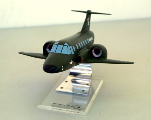
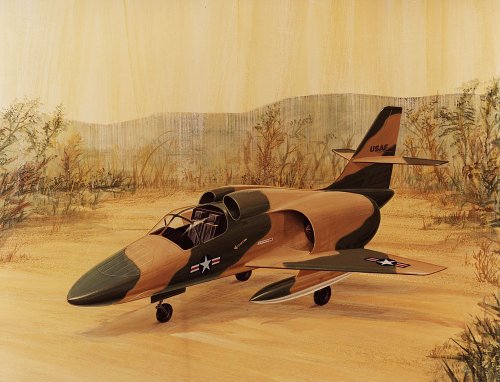
Mark Nankivil said:A piece of McAir artwork showing another iteration of the 260 design. Circle-5, is this inlet layout similar to what you were taking about?
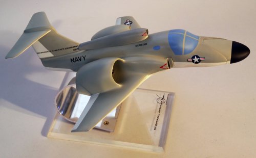
Mark, thank you for the nice color renderings. I found the model I was looking for, and it's different from your post - I wonder how many more McAir 260 versions are waiting to be discovered.
Attachments
- Joined
- 2 August 2006
- Messages
- 3,255
- Reaction score
- 1,527
What's with the nose on the model? Was it designed to be a multimission easily exchangable module? Or did it slide forward or tilt to reveal a nose mounted lift fan?
Awesome stuff you've been posting circle-5, thanks for sharing.
Awesome stuff you've been posting circle-5, thanks for sharing.
Brickmuppet
ACCESS: Secret
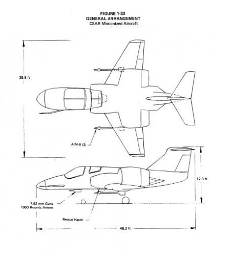
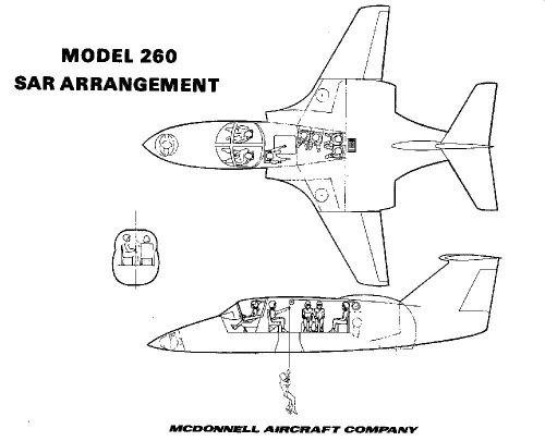
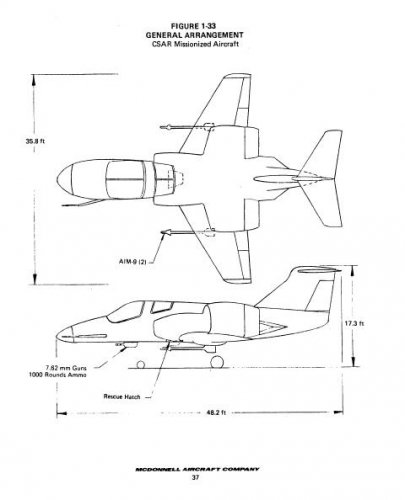
So.....How does the rescuee in the SAR version not get all burnt by the exhaust gasses?
- Joined
- 18 March 2008
- Messages
- 3,529
- Reaction score
- 978
circle-5 said:Mark, thank you for the nice color renderings. I found the model I was looking for, and it's different from your post - I wonder how many more McAir 260 versions are waiting to be discovered.
This looks like the AEW version that needs three gas generators to provide increased lift for the extra weight of the radar systems. The third dorsal intake could support the third engine and the AEW system was ventral so out of view from this photo angle.
Sundog said:What's with the nose on the model? Was it designed to be a multimission easily exchangable module? Or did it slide forward or tilt to reveal a nose mounted lift fan?
It’s just the way the model is put together. There has to be a lift fan there or the plane don’t fly.
Brickmuppet said:So.....How does the rescuee in the SAR version not get all burnt by the exhaust gasses?
The answer to your question is explained in all the documents linked to in the thread.
The Model 260 is not a Harrier, it doesn’t fly based on thrust generated by the hot exhaust of a big jet engine. The exhaust of two (or three) very small jet engines is ducted to power three (in vertical lift, two in conventional flight) big fans. While the exhaust is also vented in the fans most of the air is standard 'room' temperature. Thrust is like a turboprop aircraft and thanks to mass flow not velocity (heat).
- Joined
- 31 May 2009
- Messages
- 1,154
- Reaction score
- 674
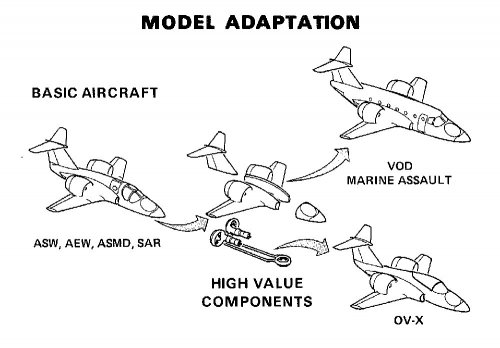
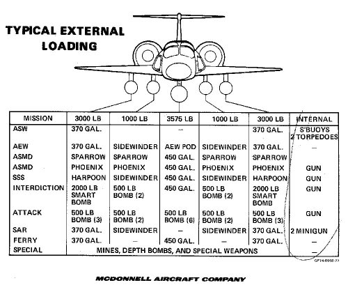
Sundog, here is your answer: that model is part of a "kit" prepared by McDonnell for decision-makers to play with. Much like a drawing posted earlier in this thread, this kit illustrates the versatility of the McAir 260, which kept the same high-value components (engines, wings, D-nozzles) for all variants. Such parts commonality would have theoretically lowered procurement and maintenance costs.Sundog said:What's with the nose on the model? Was it designed to be a multimission easily exchangable module? Or did it slide forward or tilt to reveal a nose mounted lift fan?
Attachments
- Joined
- 13 June 2007
- Messages
- 2,173
- Reaction score
- 3,093
Cool - where can I get me one of them there kits? ;D
Very interesting - thanks! Mark
Very interesting - thanks! Mark
- Joined
- 4 May 2008
- Messages
- 2,439
- Reaction score
- 762
Brickmuppet said:So.....How does the rescuee in the SAR version not get all burnt by the exhaust gasses?
I don't know about temperature, but the exhaust velocity will be a concern. By simplifying things a bit, exhaust velocity is proportional to discloading (weight / area of actuator, where the actuator could be a rotor, prop, or fan). The strength of exhaust in a CH-53 is comparable to a gale force wind. On a V-22, it's even worse. If you decrease [edit: increase!] discloading to the extreme, like in the nozzles of a Harrier, you get exhaust velocities of several hundred feet per second. Not a good place to stand behind
i'm assuming the model 260 has higher discloading than a V-22, hence higher velocities.
Brickmuppet
ACCESS: Secret
Abraham Gubler said:The answer to your question is explained in all the documents linked to in the thread.
The Model 260 is not a Harrier, it doesn’t fly based on thrust generated by the hot exhaust of a big jet engine. The exhaust of two (or three) very small jet engines is ducted to power three (in vertical lift, two in conventional flight) big fans. While the exhaust is also vented in the fans most of the air is standard 'room' temperature. Thrust is like a turboprop aircraft and thanks to mass flow not velocity (heat).
Thank you. For some reason I had it in my head that the arrangement was more like an F35 with fans and vectored direct jet thrust.
Good lord this thing looks useful!
- Joined
- 18 March 2008
- Messages
- 3,529
- Reaction score
- 978
Brickmuppet said:Thank you. For some reason I had it in my head that the arrangement was more like an F35 with fans and vectored direct jet thrust.
The concept of the GE ducted gas to tip turbine powered ducted rotors was first tested in the Ryan XV-5. This aircraft had the three tip turbine powered ducted rotors mounted on their horizontal axis for vertical flight and used the gas exhaust for horizontal flight thrust after the tip turbines were de-powered. The Model 260 changed the configuration by rotating the two wing rotors to the vertical axsis and using a vectored nozzle to force the thrust to horizontal for vertical flight. This way they take advantage of the increase in thrust from the rotors for horizontal flight over the thrust available from the gas exhaust. Which is about a factor of three...
Which is why the concept is so attractive for VTOL aircraft in that you don't need a whopping great big engine with enough exhaust for a thrust to weight ratio of 1.2 (to achieve vertical flight). You can let the rotors produce the thrust with smaller engines and save the fuel and weight. Not to mention save the weight of very heavy transmission to redirect the torque to the rotors thanks to the lighter ducting.
Of course if you're building a fighter then a TW of 1.2 is no bad thing and one of the reasons why the Harrier was the pre-eminent dogfighter of its generation, even dominating hotrods like the F-15 and Aggressor F-5Es...
Brickmuppet said:Good lord this thing looks useful!
Amen, looks like the helicopter and transmission industry dodged a bullet on this one and the rest of us are left with crappy helicopters and tilt rotors on the battlefield when we really need VTOL tip turbos...
- Joined
- 26 May 2006
- Messages
- 34,895
- Reaction score
- 15,759
- Joined
- 27 December 2005
- Messages
- 17,748
- Reaction score
- 26,408
Thanks Hesham but in fact you already posted this PDF and these pictures earlier in the topic ;D
- Joined
- 26 May 2006
- Messages
- 34,895
- Reaction score
- 15,759
overscan said:Thanks Hesham but in fact you already posted this PDF and these pictures earlier in the topic ;D
Yes my dear Overscan,
and sorry for this double post.
- Joined
- 13 June 2007
- Messages
- 2,173
- Reaction score
- 3,093

Similar threads
-
 McDonnell-Douglas Model 265 AFTI project
- Started by overscan (PaulMM)
- Replies: 79
-
REQUIREMENT: US Navy VFA - V/STOL Fighters for Sea Control Ships
- Started by overscan (PaulMM)
- Replies: 5
-
VFAX (1974) / NACF Projects (Pre F/A-18 concepts)
- Started by overscan (PaulMM)
- Replies: 53
-
 McDonnell-Douglas Model 279 VSTOL fighter
- Started by Deino
- Replies: 43
-
 US Navy "V/STOL Type A" competition
- Started by flateric
- Replies: 55