
You are using an out of date browser. It may not display this or other websites correctly.
You should upgrade or use an alternative browser.
You should upgrade or use an alternative browser.
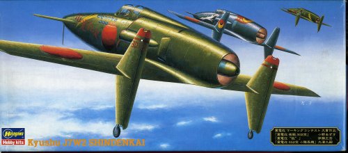
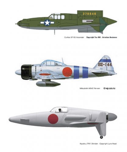
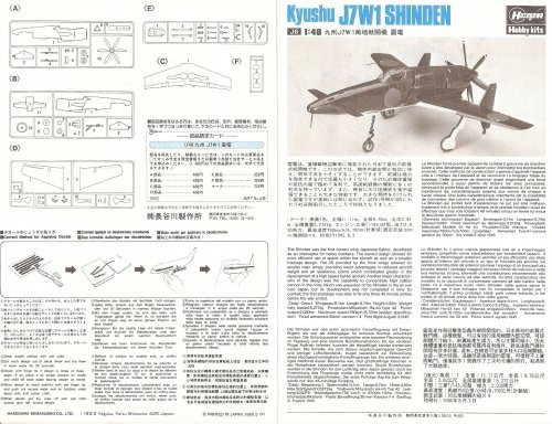
Kyushu J7W1 Shinden/J7W2 Shinden-kai
- Thread starter hesham
- Start date
blackkite
Don't laugh, don't cry, don't even curse, but.....
- Joined
- 31 May 2007
- Messages
- 8,819
- Reaction score
- 7,716
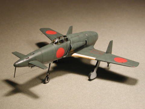
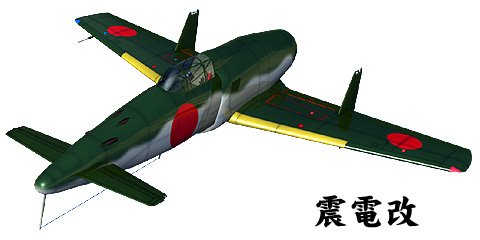
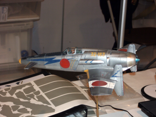
Hi! We can find some Shinden-kai models or drawings in Internet site.
This is one model. But it's not necessary to have two types of air intake.
Original Shinden have two types of air intake. One is for engine cooling. Another one is for supercharger.
But Shinden-kai needs only one type of air intake for jet engine.
http://www9.plala.or.jp/fukugiya/72-081-shinden-jet.htm
Attachments
blackkite
Don't laugh, don't cry, don't even curse, but.....
- Joined
- 31 May 2007
- Messages
- 8,819
- Reaction score
- 7,716
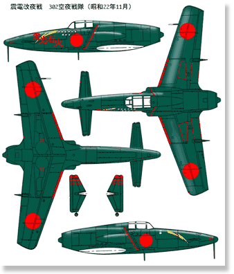
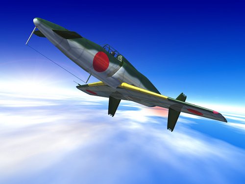
I think these models have rather proper shape air intake.
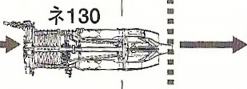
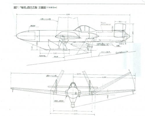
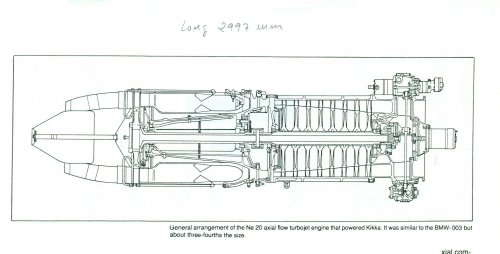
Shinden-kai was planned to have Ne-130 jet engine.(Thrust : 900kg, equal to about 3000hp)
Shinden-kai was planned to have Ne-130 jet engine.(Thrust : 900kg, equal to about 3000hp)
Attachments
blackkite
Don't laugh, don't cry, don't even curse, but.....
- Joined
- 31 May 2007
- Messages
- 8,819
- Reaction score
- 7,716
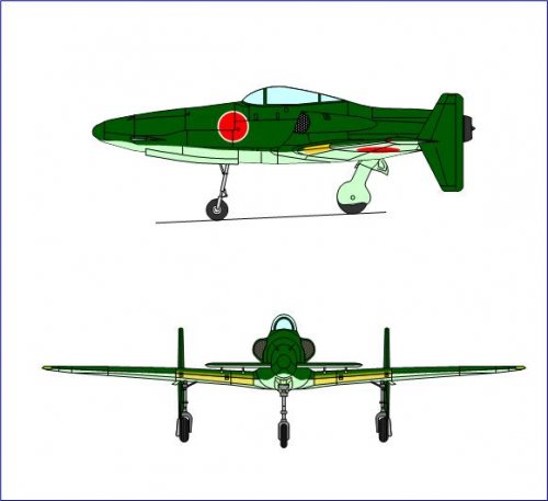
Many thanks Justo. Excellent! ")
I want to see front view. How about adding air intake boundary layer fence? Or how about bottom drawing's intake shape.
I want to see front view. How about adding air intake boundary layer fence? Or how about bottom drawing's intake shape.
Attachments


blackkite
Don't laugh, don't cry, don't even curse, but.....
- Joined
- 31 May 2007
- Messages
- 8,819
- Reaction score
- 7,716

Taranov
ACCESS: Confidential
- Joined
- 23 January 2011
- Messages
- 119
- Reaction score
- 43
blackkite said:Thanks another opinion. Splendid drawing.
Engine : Ishikawa Ne-440??
Speculative data ;D
blackkite
Don't laugh, don't cry, don't even curse, but.....
- Joined
- 31 May 2007
- Messages
- 8,819
- Reaction score
- 7,716
Officially there are no jet powered Shinden drawing. Name of Shinden-kai is not official,too.
Kyushu Hikoki did not start jet powered Shinden design until the end of the war.
Engineer of Kyushu hikoki(Kunitake Kiyohara, section submanager of No.1 design section of Kyushu Hikoki) said so.
But it's true that the IJN ordered Kyushu Hikoki to design Shinden considering future turbo jet engine installation.
Engine was Ne-130, thrust 900kg, estimated jet powered Shinden's maximum speed with Ne-130 engine was 420kt(780km/h).
The IJN planned that jet powered Shinden use JATO when take off.
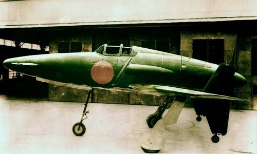
Shinden had laminar flow wing.(Maximum thickness located 45% wing chord.)
Sourec : Aireview magazine, extra number, Unknown military aircraft development(Vol.1/2) page 51, March 1999, ISBN4-87357-049-2 C9453
Kyushu Hikoki did not start jet powered Shinden design until the end of the war.
Engineer of Kyushu hikoki(Kunitake Kiyohara, section submanager of No.1 design section of Kyushu Hikoki) said so.
But it's true that the IJN ordered Kyushu Hikoki to design Shinden considering future turbo jet engine installation.
Engine was Ne-130, thrust 900kg, estimated jet powered Shinden's maximum speed with Ne-130 engine was 420kt(780km/h).
The IJN planned that jet powered Shinden use JATO when take off.
Shinden had laminar flow wing.(Maximum thickness located 45% wing chord.)
Sourec : Aireview magazine, extra number, Unknown military aircraft development(Vol.1/2) page 51, March 1999, ISBN4-87357-049-2 C9453
blackkite
Don't laugh, don't cry, don't even curse, but.....
- Joined
- 31 May 2007
- Messages
- 8,819
- Reaction score
- 7,716
Attachments
blackkite
Don't laugh, don't cry, don't even curse, but.....
- Joined
- 31 May 2007
- Messages
- 8,819
- Reaction score
- 7,716
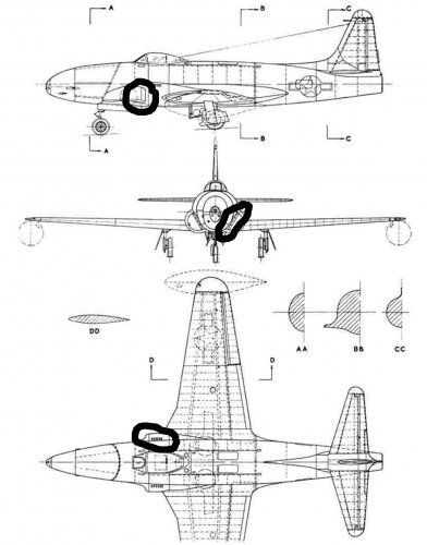
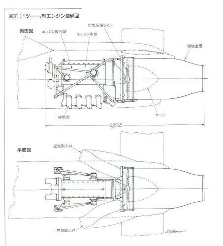
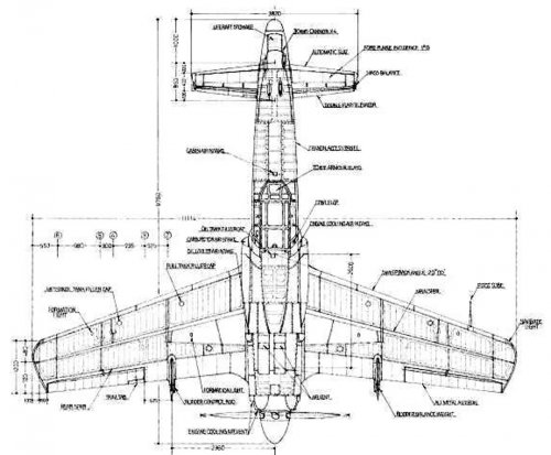
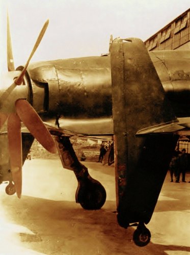
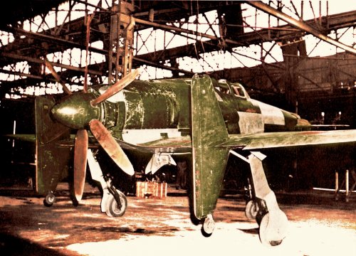
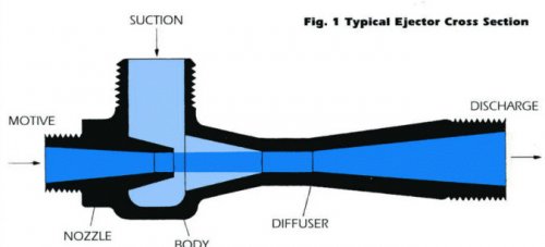
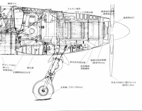
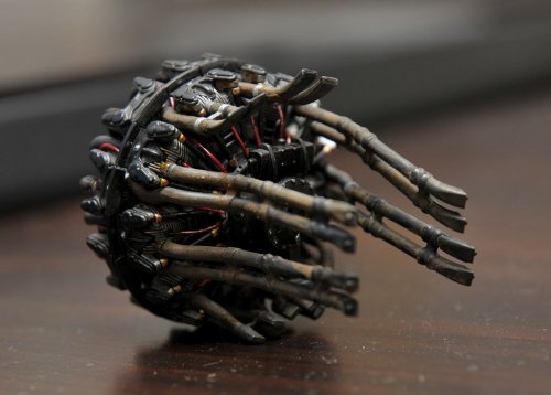
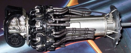
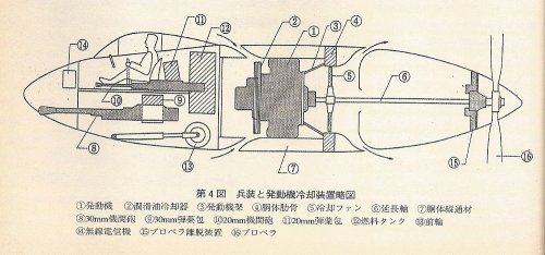
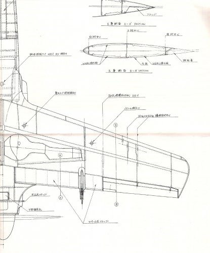
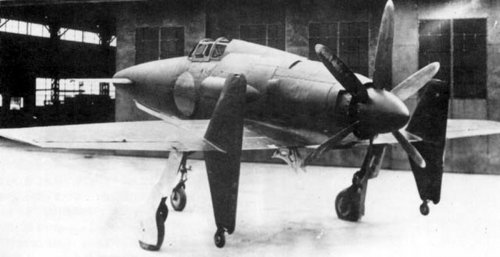
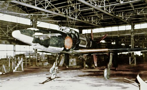
Shinden's engine had 18 exhaust nozzles.
4 nozzles exhaust gas were used for thrust.(Located upper part of the engine.)
8 nozzles exhaust gas were used for ejector(jet pump) which take oil cooler cooling air. (Located middle part of the engine.)
6 nozzles exhaust gas were used for ejector which exhaust engine room hot air.(Located bottom part of the engine.)
Of course engine was cooled by mainly forced cooling air by forced cooling fan which located behind the engine.
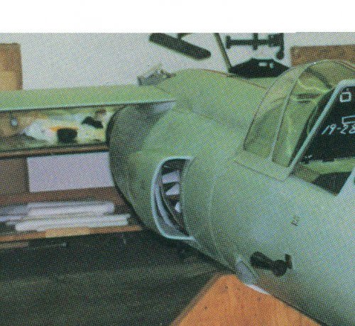
You can see oil cooler air intake in the 4th picture.(After end of the fuselage)
4 nozzles exhaust gas were used for thrust.(Located upper part of the engine.)
8 nozzles exhaust gas were used for ejector(jet pump) which take oil cooler cooling air. (Located middle part of the engine.)
6 nozzles exhaust gas were used for ejector which exhaust engine room hot air.(Located bottom part of the engine.)
Of course engine was cooled by mainly forced cooling air by forced cooling fan which located behind the engine.
You can see oil cooler air intake in the 4th picture.(After end of the fuselage)
Attachments
-
 engine room hot gas exit.jpg48 KB · Views: 258
 -
 thrust gas exit.jpg107.1 KB · Views: 304
 -
 Oil cooler.jpg173.6 KB · Views: 329
 -
 Ejector concept.jpg30.7 KB · Views: 308
 -
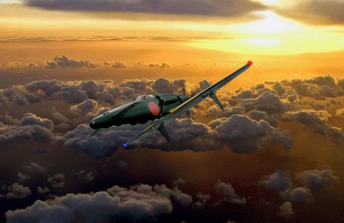 in flight.jpg389.6 KB · Views: 377
 -
 Shinden engine 1.jpg165.4 KB · Views: 392
 -
 Shinden engine exhaust pipe.jpg242 KB · Views: 315
 -
 Shinden engine 2.jpg153.9 KB · Views: 780
windswords
ACCESS: Secret
- Joined
- 19 May 2009
- Messages
- 389
- Reaction score
- 217
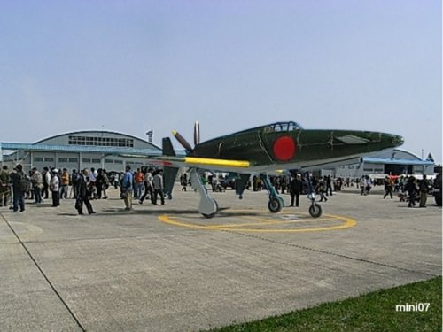
blackkite said:We hope Shinden restoration in the U.S.Washington D.C. B)
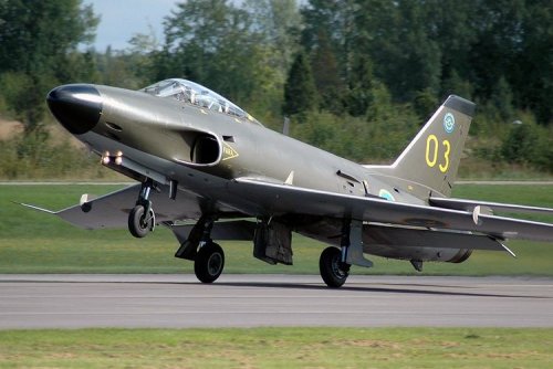
I have always wanted to see two aircraft restored and put on display at the Smithsonian: The Horten Ho-229 and the J7W1. If they were done I would take a vacation to Washington DC just to see those two planes.
blackkite
Don't laugh, don't cry, don't even curse, but.....
- Joined
- 31 May 2007
- Messages
- 8,819
- Reaction score
- 7,716
Thanks windswords! Me,too.windswords said:blackkite said:We hope Shinden restoration in the U.S.Washington D.C. B)
I have always wanted to see two aircraft restored and put on display at the Smithsonian: The Horten Ho-229 and the J7W1. If they were done I would take a vacation to Washington DC just to see those two planes.
I used to visit Fort Lauderdale and Miami. Florida was worm in winter.
http://www.youtube.com/watch?v=C2ifDWxkVGs
blackkite
Don't laugh, don't cry, don't even curse, but.....
- Joined
- 31 May 2007
- Messages
- 8,819
- Reaction score
- 7,716
Hi! 3 side view. Please push flag of each country.
http://www.airwar.ru/other/draw_fw.html
http://www.airwar.ru/other/draw_fw.html
blackkite
Don't laugh, don't cry, don't even curse, but.....
- Joined
- 31 May 2007
- Messages
- 8,819
- Reaction score
- 7,716
Hi! I think it's my responsibility. Sorry not enough.Basil said:Blackkite, thanks for the detailed pictures of the exhaust / ejector cooling system of the Shinden. It's hard to get these informations as a non japanese speaking person.
I realize Shinden shape demerit one more.
It's hard to cool engine and oil when ground engine test, because engine and oil cooler are not exposed high speed propeller after stream.
Perhaps it's one of the reason why Shinden had a forced cooling fan and ejector type oil coolers.
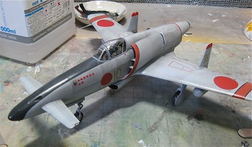
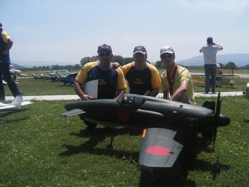
And R/C model.
http://homepage2.nifty.com/96fighter/E_scr_J7W1.htm

blackkite
Don't laugh, don't cry, don't even curse, but.....
- Joined
- 31 May 2007
- Messages
- 8,819
- Reaction score
- 7,716
blackkite
Don't laugh, don't cry, don't even curse, but.....
- Joined
- 31 May 2007
- Messages
- 8,819
- Reaction score
- 7,716
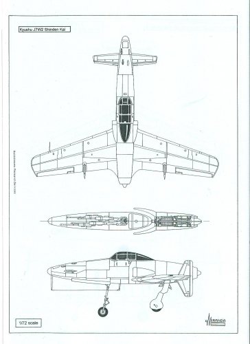
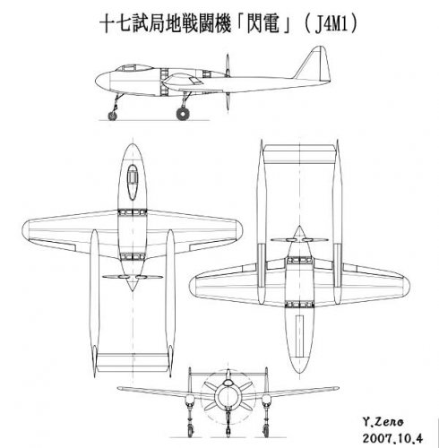
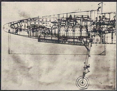
Hi!
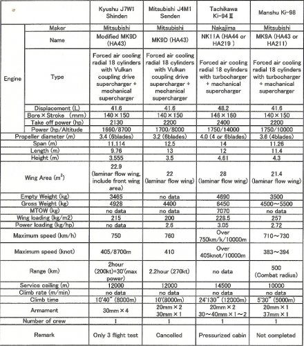
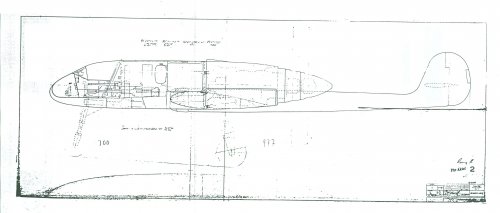
Senden arrangement.
①Engine ②Oil cooler ③Engine mounting ④Fuselage frame ⑤Forced cooling fan ⑥Extended propeller shaft ⑦Fuselage longitudinal frame ⑧30mm cannon ⑨30mm cannon cartridge ⑩20mm cannon ⑪20mm cannon cartridge ⑫Fuel tank ⑬Front gear ⑭wireless apparatus⑮Propeller breakaway mechanism ⑯Propeller
Senden was cancelled in October 1944 due to MK9D engine under power, failure of Vulkan coupling development or failure of Vulkan coupling application to MK9D engine and extended propeller shaft trouble.
Senden’s engine cooling problem was clearly solved by the test (9 months) using MK9D engine and full scale fuselage model. Horizontal tail stabilizer vibration was clearly solved by the wind tunnel test and the design change.
(Source : Senden’s chief designer Eitaro Sato’s report)
I think Shinden received some feedback from Senden’s failure.
For example, MK9D engine modification(the first stage supercharger design including Vulkan coupling, oil cooler concept and extended propellre shaft design). Don't you think so?
Shinden’s first stage supercharger shape is different from Senden’s one.
Shinden’s first stage supercharger had twin impeller, but fromSenden’s arrangement drawing, I feel Senden’s first stage supercharger had a single impeller.
Attachments
- Joined
- 31 May 2006
- Messages
- 657
- Reaction score
- 440
This is great information Blackite - thank you!
May I just ask - the 'Vulkan Coupling', this was Daimler Benz technology adapted by Mitsubishi for their engines? If Mitsubishi couldn't get the technology to work could they have used a more conventional approach to two speed supercharger control?
May I just ask - the 'Vulkan Coupling', this was Daimler Benz technology adapted by Mitsubishi for their engines? If Mitsubishi couldn't get the technology to work could they have used a more conventional approach to two speed supercharger control?
blackkite
Don't laugh, don't cry, don't even curse, but.....
- Joined
- 31 May 2007
- Messages
- 8,819
- Reaction score
- 7,716
Hi Nick!Nick Sumner said:This is great information Blackite - thank you!
May I just ask - the 'Vulkan Coupling', this was Daimler Benz technology adapted by Mitsubishi for their engines?
I think that's right. Perhaps Mitsubishi got Vulkan coupling technology from Kawasaki. Kawasaki already applied this technology to Hien's Ha-40 engine. The merit of using Vulkan coupling is high climb rate. It was very important characteristic for the interceptor.
If only Vulkan coupling was adjusted properly, HA-40 engine worked well at the day.
blackkite
Don't laugh, don't cry, don't even curse, but.....
- Joined
- 31 May 2007
- Messages
- 8,819
- Reaction score
- 7,716
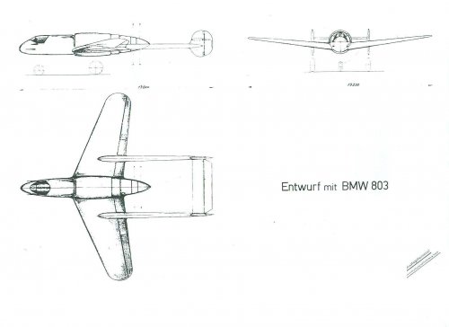
Wow thanks Justo!
The German is one of the our best teacher in the past, now and in the future.
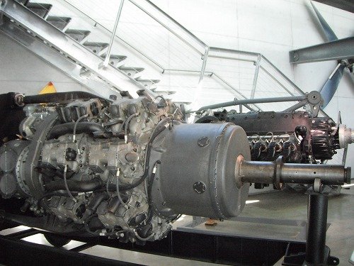
The engine was liquid cooling double array radial engine BMW803. B)
The radiator was located behind the big forced cooling fan.
The German is one of the our best teacher in the past, now and in the future.
The engine was liquid cooling double array radial engine BMW803.
B) The radiator was located behind the big forced cooling fan.
Attachments
- Joined
- 26 May 2006
- Messages
- 34,901
- Reaction score
- 15,761
Justo Miranda said:Similar comparative german project here
What was the last two aircraft?, Focke Wulf projects or not .
Focke Wulf Jäger projekt mit BMW 803 , and Heinkel "Kartusche" ejector seat.
windswords
ACCESS: Secret
- Joined
- 19 May 2009
- Messages
- 389
- Reaction score
- 217
chuck4 said:Is there any provision for the pilot to avoid the props during bailout?
If you look at one of the the diagrams posted by Blackkite it refers to number 15 as "Propeller breakaway mechanism". Maybe it's some kind of explosive charge to blow off the prop so the pilot can bail out.
blackkite
Don't laugh, don't cry, don't even curse, but.....
- Joined
- 31 May 2007
- Messages
- 8,819
- Reaction score
- 7,716
blackkite
Don't laugh, don't cry, don't even curse, but.....
- Joined
- 31 May 2007
- Messages
- 8,819
- Reaction score
- 7,716
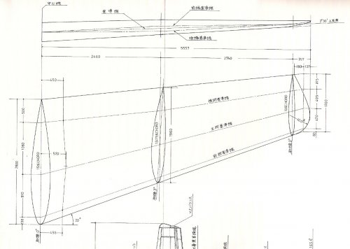
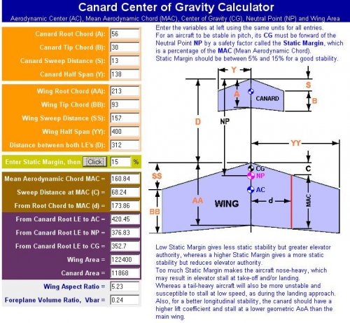
Shinden’s main wing was a laminar flow wing, maximum thickness located 45% wing chord.
Wing root and wing tip angle of attack was 0 degree while wing middle position's angle of attack was 3 degee.
Front wing area was 10% of main wing area.
Front wing span and wing chord were 1/3 of main wing.
Front wing aerodynamic effect to the main wing was small.
Front wing had leading edge slat and double flap (slotted flap + plain flap).
Double flap also had the function of elevator.
Angle of attack of front wing was 1 degree.
Attachments
blackkite
Don't laugh, don't cry, don't even curse, but.....
- Joined
- 31 May 2007
- Messages
- 8,819
- Reaction score
- 7,716
Attachments
blackkite
Don't laugh, don't cry, don't even curse, but.....
- Joined
- 31 May 2007
- Messages
- 8,819
- Reaction score
- 7,716
If possible, please marge this topic.
And change the title. For example, "Kyushu J7W1 Shinden and Shinden-kai".
Thanks Jens.
http://www.secretprojects.co.uk/forum/index.php/topic,16984.0.html
And change the title. For example, "Kyushu J7W1 Shinden and Shinden-kai".
Thanks Jens.
http://www.secretprojects.co.uk/forum/index.php/topic,16984.0.html
blackkite
Don't laugh, don't cry, don't even curse, but.....
- Joined
- 31 May 2007
- Messages
- 8,819
- Reaction score
- 7,716
Hi!
Please watch products. And bottom movie.
http://www.zoukeimura.co.jp/en/index.html
And some pictures.
Please watch products. And bottom movie.
http://www.zoukeimura.co.jp/en/index.html
And some pictures.
Attachments
blackkite
Don't laugh, don't cry, don't even curse, but.....
- Joined
- 31 May 2007
- Messages
- 8,819
- Reaction score
- 7,716
Hi! Total 13 pages. Enjoy.
Please watch RC model crush scene in page 13.
http://www.rcgroups.com/forums/showthread.php?t=642695
Please watch RC model crush scene in page 13.
http://www.rcgroups.com/forums/showthread.php?t=642695
Attachments
Similar threads
-

-

-
 Yokosuka (Yokosho/Yosho, Kugisho/Kusho) related topics on this forum
- Started by Stargazer
- Replies: 0
-
-
 IJN Specification 12-Shi (E12/E13, Reconnaissance Seaplane, 1937)
- Started by blackkite
- Replies: 25