Kawanishi Baika
Would Japan have not surrendered after the atomic attacks over Hiroshima and Nagasaki in August 1945, the Allies would have been forced to land on the Japanese home islands. There were plans to carry out the invasion in two phases. The first step, known as ‘Operation Olympic’, aimed to occupy the south of Kyushu Island and should start on November 1st. The second one, ‘Operation Coronet’, would have consisted of landings on Honshu Island, to control the Tokyo plain, and it was planned for March 1946. The whole plan, ‘Operation Downfall’, required 5,000,000 men, 3,000 ships, 66 aircraft carriers, loaded with 2,649 aircraft, and all the airplanes in the 7th, 8th and 10th Army Air Forces. Casualties were expected to be extremely heavy. A study requested by U.S. Navy Secretary estimated that conquering Japan would cost between 1.7 and 4 million casualties including 400,000 to 800,000 fatalities and the destruction of 800 Allied ships.
The defensive plan of the Japanese High Command (Operation
Ketsu-Go) included the use of the 12,725 airplanes available in one single and uninterrupted attack with the purpose of collapsing the defences of the Allied fleet. A force of 2,000 IJA and IJN Japanese fighters would battle to control the skies over Kyushu Island. While the Allied fleet would still be in open sea and approaching Japan, the warships of the Task Force would be attacked by 330 IJN suicide bombers, then a group of 825 IJA and IJN suicide airplanes would try to sink the troop transports. Once the invasion ships got close to their proposed anchorages, another 2,000 suicide aircrafts would be launched hour after hour in nonstop attacks which the Japanese hoped could be sustained for 10 days. Thirty five camouflaged airfields and nine seaplane bases had been built in Kyushu to that purpose. The Japanese also had 20 suicide take off strips with underground hangars, from where the Ki.115
Tsurugi and
Baika Model 1 could operate.
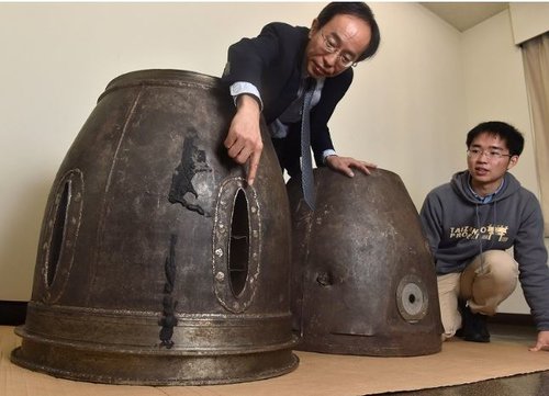
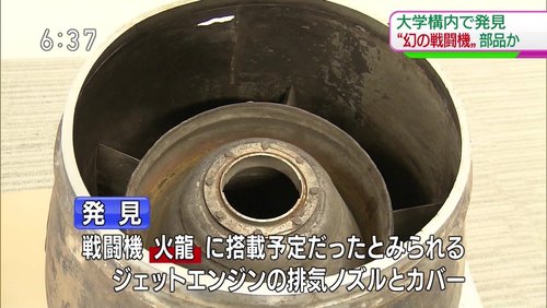
The
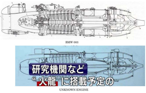
Ohka 43-Otsu would use some straight railway sections and rocket-propelled trolleys to operate. It was very effective but had the handicap of using the new Ne-20 turbojet of which just a few units were available. The Ki.115 could use several types of second hand conventional engines but it required 80 octane gasoline which was almost non-existent in Japan due to the naval blockade. On the other hand, the Ne-20 could work with a mixture of wood turpentine and charcoal, although the battered Japanese industry could not manufacture them in high numbers on time for
Ketsu-Go.
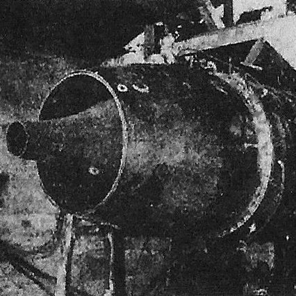
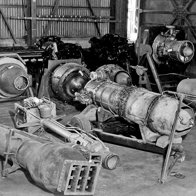
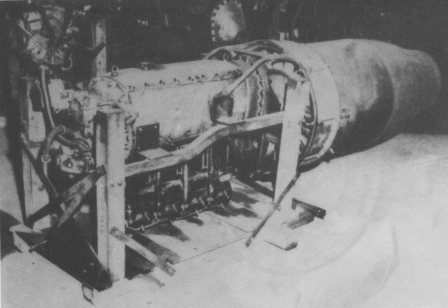
The Japanese scientists found the solution to this situation with the mass production of pulsejet engines based on the Argus As 109-014 scale drawings that the I-8 submarine had brought from Germany in 1943. The Japanese version, known as
Maru Ka-10 was designed by professors Ichiro Tami and Taichiro Ogawa of the Aeronautical Institute of Tokyo Imperial University in 1944. The
Maru Ka-10 was 3,750 mm long, had 550 mm of diameter and weighted 153 kg, producing 360 kg of thrust at 740 kph. It used Benzol as fuel during the flying tests, although it could also work with low quality oil or heavy kerosene. It was expected that the operational version would burn 1,600 lt of crude pine root oil that the local chemical industry produced as
ersatz fuel.
The Japanese did never receive the blueprints for the V-1 missile or for their manned variant
Reichenberg as the German submarine carrying them was sunk. They were forced to design their own version based in a general description of the German model. The result was a small low wing monoplane made out of wood and steel, given the scarcity of aluminium. By the beginning of 1945 their mass production was ordered to the Kawanishi Kokuki K.K. firm, under the
Baika denomination. The plan was to manufacture three different versions.
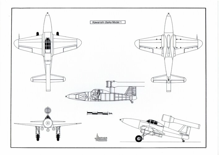
The first one was the Kawanishi
Baika model 1 that took off from a conventional aerodrome reaching the ignition speed of the pulsejet (360 kph) thanks to the thrust of its three
Toku-Ro.1 Type 2 rockets with 600 kg of thrust, located in the wing roots and in the fuselage centreline. Its main undercarriage (from a Ki.115) and the rockets (from an
Ohka 43) were jettisoned after take-off. The high rate of fuel consumption of the pulsejet allowed a range of just 204 km at the cruise speed of 556 kph and sea level. The model 1 could only operate against troops transports located near the southern coast of Kyushu. To that purpose they planned to have a Type 97 warhead with 150 kg of Torpex H.E. (from a Type 91 mod.1 airborne torpedo) to impact under the ship waterline.
The Kawanishi
Baika model 2 was the second version. During the WWII the Japanese used 46 submarines with capacity to carry different types of airplanes in deck watertight hangars. By August 1945 they still kept six of them: The I-14 (AM class) with a hangar of 4.2 x 21 m. able to house two
Seiran bombers, the I-36 (B1 class) and the I-58 (B3 class) with a hangar of 1.4 m high, 2.4 m. wide and 8.5 m long where they could transport a Watanabe reconnaissance floatplane and the I-400, I-401 and I-402 of the
Sen-Toku Class that had a hangar of 4.2 m. of diameter and 31 m long with capacity for two
Saiun or three
Seiran or four
Ohka type 43-Ko.
These submarines were ideal to transport specialized suicide airplanes that could attack the enemy fleet in their bases of Ulithi, Pearl Harbour, the west coast of USA or even when they were crossing the Panama Canal. They could be refuelled during the trip by the I-402, specially modified as tanker to that purpose. The I-400 could even reach New York and Washington going round South America from the south in a four months journey. Would the Allies have used poison gas against Iwo Jima in February 1945, New York could have been attacked in June using Type 7 bacteriological bombs, launched from six
Seiran airplanes carried by the
Sen-Toku submarines.
To compete against the O
hka type 43-Ko, the Kawanishi firm designed a
Baika model 2 version to be launched from submarines. To facilitate their storage it was considered convenient to reduce their length in 63 cm moving forward the support structure of the pulsejet. The clear cockpit opened sliding forward. The wings were built in such a way that could be folded backwards, like in the
Seiran, and put back in flying position very quickly using a hydraulic mechanism connected to the submarine. The warhead was a general purpose 250 kg bomb with nose priming plug and rear impact fuse.
The
Baika model 2 used the same launch system than the
Ohka type 43-Ko. It was positioned over a launch cart of 700 kg at the end of a catapult (26 m length, 116 cm track and 3º30’ pitch) shot by a 90-150 kg/sq. cm compressed air device coming from the torpedo launch system of the submarine. A buffer cable was used for decelerating the launch cart that was quickly stored under the deck. The four airplanes of a
Sen-Toku could be launched within 20 minutes. The time required was of 6 min 23 sec for each from the oldest submarines.
The last version of the
Baika was the model 3. One of the main reasons of the operational failure of the
Ohka model 11 was the excessive weight of their warhead which had been designed for the single shot destruction of major warships.
To cover this gap, the Kawanishi firm designed an air launched variant of the
Baika. Instead of solving the problem of integration with the
Ginga by reducing the wingspan, so that it could be housed between the main undercarriage legs, the manufactured airplane weighted half the weight of an
Ohka 11 and could be installed in a more rearward position within the
Ginga bomb bay. To allow the ignition of the pulsejet during flight, it should be exposed to the air stream outside the carrier airplane. Its original location was therefore moved to below the fuselage centreline of the
Baika. Although the cruise speed of the model 3, when launched from 6,100 m, was of just 481 kph, it started a shallow dive at 556 kph until being intercepted by the fighters flying at 600 kph. It then increased the dive angle until reaching 740 kph passing under the fighters screen and going to the target at sea level, impacting under the waterline, or climbing at 450 m to go down over the ship deck in a 75º dive, depending on the type of warhead used.
At this point of time the Japanese were no more interested in sinking the big heavily armoured warships. The political circumstances were more favourable to the kind of war that caused a high number of casualties to the Allies. It was better to try and destroy the little protected troop transports with a warhead of just 250 kg.
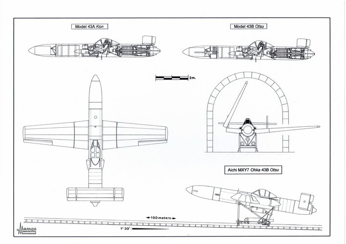
Kugisho MXY7 Ohka
The
Ohka 43-Ko carried the same warhead (version of 800 kg) than the
Ohka Model 33 but without the nose priming plug. Its fuel tank capacity was of 400 litres and it was located between the warhead and the main spar. The oil tank of 16 litres was between the pilot seat and the turbojet. It could reach targets placed 278 km from the launch point.
The ‘Ko’ version did not use auxiliary dive rockets. It released the folding wingtips by means of electrically activated explosive bolts, during the terminal dive to increase its speed. It was expected that it could surpass the 900 kph when reducing its wingspan to just 2.6 m. At this stage control was obtained by using the tail surfaces that could move in differential mode to act as ailerons. In normal configuration, the Model 43 had 13 sqm of wing surface, 4º 30' of dihedral angle and 2º 30' of tail plane incidence.
The ‘Otsu’ version was designed to take off from a 110 m length straight railway section and hide in the railway tunnels with its wings folded. Developed to avoid the use of conventional aerodromes in a situation of complete aerial superiority of the enemy, it was inspired by the launch procedure of the Messerschmitt P.1079 (July 3, 1942). The idea was to use it in a long range coastal artillery role to counteract the invasion of southern Kyushu, or ‘Olympic Operation’, which was expected to happen on November 1, 1945.
The Model 43-Otsu used a launch cart for take off similar to one used by the naval version but propelled by two
Toku-Ro.1 Type 2 rocket engines with 600 kg thrust each and 30 seconds of life and by the power of its own Ne-20 turbojet. At the end of its run the cart was detached and braked by a cable and a counterweight system. At that moment, a third
Toku-Ro.1 Type 3 rocket with 600 kg peak thrust and 20 seconds endurance automatically ignited. This was fixed to the fuselage centreline and its nozzle had an 8º 45' slope to make the thrust axis and the gravity centres of the
Ohka converge, thus providing maximum lift.
The land version used the same warhead than the naval one but it was armed with two Type 3 machine guns of 13 mm with a rate of fire of 800 rpm located between the warhead and the fuel tank, which capacity had been reduced to 300 lt, and a combat range to 200 km. The guns configuration was inspired by the German air to air rocket bomber Sombold So 344 project and its objective was that the
Ohka could break its way towards the Allies Task Forces fighting against the defensive fighters to which it was equal in speed. The ‘Otsu’ kept the mechanism to detach the wingtips of the naval version but was not considered a requirement to equip it with accelerator rockets for the terminal dive. It was expected that it would be able to surpass the 900 kph in a 50º dive with the Ne-20 at full throttle.
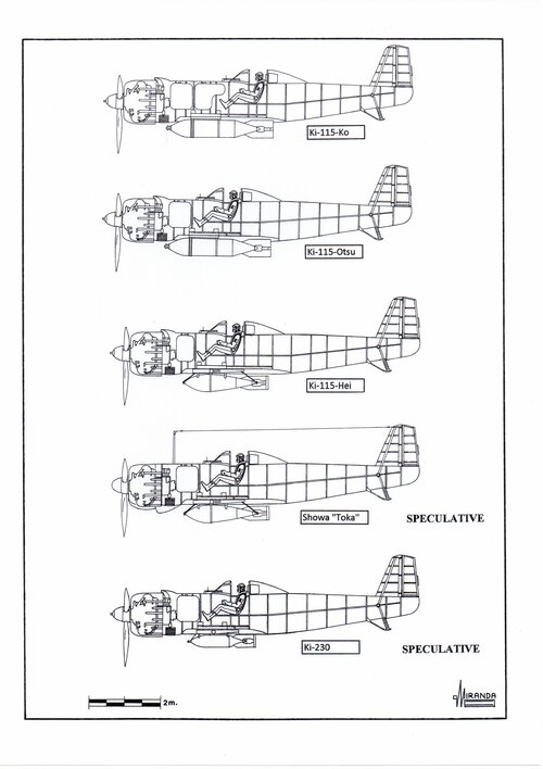
Nakajima Ki.115-Ko Tsurugi
Following the great loss of suicide airplanes during the American invasion of the Philippines, the IJA requested Nakajima to design an expendable suicide bomber on January 20, 1945. The mass production programme was known as
Kokoku Heiki Go.3 and focused on the aircraft being easy to build by semi-skilled labour, using non-strategic materials and propelled by any surplus radial engine, with a power in the range between 800 and 1,500 hp.
The flight tests of the prototype started only seven weeks later, detecting serious problems of stability, poor handling and take off performance. The droppable landing gear was modified to improve its elasticity and equipped with drum brakes. Auxiliary flaps were attached to the trailing edge of the wing and anchor points for two
Toku-Ro.1, Type 3 RATO rockets had to be fixed under the wings.
The Nakajima plants of Ota and Iwate assembled 104 aircrafts from externally supplied components between March and August 1945. All these aircrafts were powered by a Nakajima Ha-115-II engine of 1,130 hp, from the Ki.43-II-Otsu fighters, with one 2.9 m diameter, three bladed, fixed pitch propeller. The wing structure and cladding was still of light alloy in this first series, but in Nakajima they were studying the steel manufacturing techniques inspired on the German missile V-1. To facilitate construction, the fuselage had circular section and was fully made of steel. The tail surfaces were made of wood with control surfaces clad by fabric. The engine cowling was made of tin. The Ha-115 engine was fastened to the fuselage using four bolts only.
Designed to counteract the foreseeable invasion of Okinawa, taking off from the airfields to the south of Kyushu, the
Tsurugi had a range of 1,200 km, ensured by two fuel tanks of 240 litres each positioned between the engine and the cockpit. In theory, it could even return to base or use only one tank, with the valuable 80 octane fuel, and fill the other tank with some kind of inflammable substance to magnify the destructive effect after the impact.
Partially recessed within the belly, the
Tsurugi could transport one fixed antiship bomb of 250, 500 or 800 kg. The ’Ko’ version had a 8.6 m wingspan, 8.55 m length, 3.3 m high and 12.39 sq. m wing area. The maximum take off weight was of 2,630 kg and the estimated maximum speed of 551 kph.
When flights tests ended in June, it was made apparent that the aircraft was not suited for its use in combat by poor trained pilots, even after the modifications, and could not be used in the Battle of Okinawa.
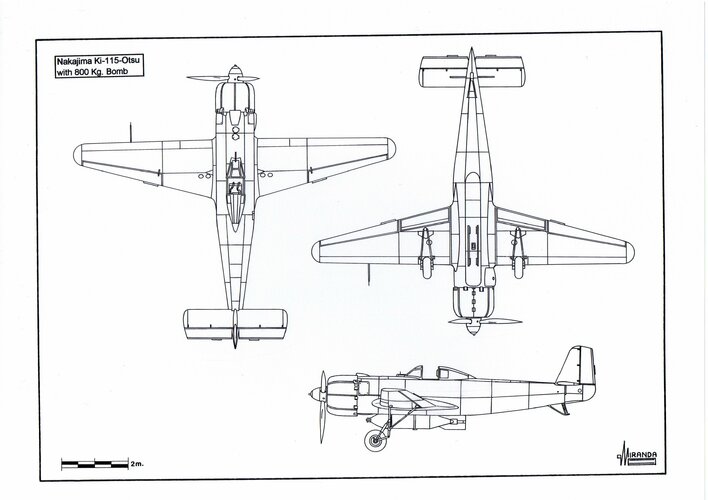
Nakajima Ki.115-Otsu Tsurugi
This new version was designed to correct the handling problems experienced with the Ki.115-Ko by increasing the wingspan up to 9.69 m and the wing surface to 14.49 sq. m. Only nine units were built before the end of the WWII. They were propelled by a Mitsubishi Ha-112 engine of 1,500 hp, used by Kawasaki Ki.100 fighters, providing a maximum speed of 620 kph.
The wings were of wood/plywood, with integrated flaps. The ailerons structure was of light alloy with cladding of fabric. The fuselage and tail surface were those of the Ki.115-Ko, rejected by the IJA. The range was reduced when one of the fuel tanks was removed, but this allowed advancing the position of the cockpit to improve pilot visibility during take off. Loaded with a Number 80, Model I, of 807.5 antiship bomb, the Otsu weighted 2,880 kg.
Nakajima Ki.115-Hei Tsurugi
The ’Hei’ version reached the project phase only. Specifically designed to counteract the expected invasion of Kyushu Island ‘Operation Olympic’ this aircraft would enter into action when the transports of Allied fleet would be at a distance of 290 km from the beaches.
The ‘Hei’ was basically a version of the ‘Otsu’, entirely built of wood/plywood. Considering the short range of the flight and the generalised shortness of petrol, the size of the fuel tank was reduced (possibly down to 120 litres) and the pilot seat moved further to the front.
As it was expected that some pilots could be recovered, to take part in further attacks, the ‘Hei’ was equipped with a bomb release system that possibly was the same used by the
Zeros for the Number 50 Model 2 of 507 kg antiship bomb.
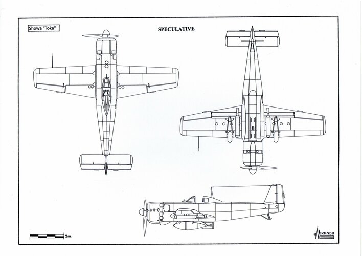
Showa Toka
It was the version of the Ki.115-Ko for the IJN, with some modifications acquired from the Ki.115-Otsu. The flaps were modified as dive brakes, it had a single 450 litres fuel tank and the front cockpit was moved forward, as well as some additional naval equipment: an RT radio set to communicate with the guiding aircrafts, two under wing Toku-Ro.1 Type 3 with 600 kp peak thrust RATO rockets and two under wing iron tube launchers for I.S.R. 12 cm barrage rockets.
The
Toka was designed to use different surplus engines:
Kotobuki 41 of 785 hp, from the A5M
Claude fighters;
Sakae 12 of 1,130 hp, from the A6M2
Zeros;
Zuisei 12 of 875 hp, from the C5M
Babs;
Kinsei 41 of 1,075 hp, from the G3N bombers;
Kinsei 53 of 1,300 hp, from the H6K flying boats.
It had the same wingspan than the Ki.115-Ko, but the wing area was increased up to 13.10 sqm. A study by Nakaijma stated that the
Toka could not transport 800 kg bombs, due to the additional weight of the naval equipment. It was expected to manufacture 850 units during the second half of 1945, using construction systems that required only 10 percent of the man hours needed for the
Zero. Its empty weight was 1,700 kg.
The IJN also considered the possibility of manufacturing a version of the
Toka entirely made of wood and possibly inspired on the Ki.115-Hei.
Nakajima Ki.230
It appears to be a project based on the Ki.115-
Otsu, made of wood, and able to carry a bomb of 250 or 500 kg. Underpowered by an engine Ha-115-I of 1,105 hp, from the Ki.43-I-Ko fighters, and with the same empty weight than the
Toka, the Ki.230 required a wingspan increased up to 9.69 m and a wing area of 13.09 sqm to take off without the help of the RATO rockets. Its estimated maximum speed, with a bomb of 250 kg, was of 557 kph.
It was possibly intended to be used to mass attack the transports of troops during the ‘Operation Coronet’, at a time when the
Ketsu-Go Japanese strategy consisted of causing the biggest number of casualties to the Allies. With this strategy, they hoped that social structure of democracies could not stand the waste of human resources.

 karyu.org