- Joined
- 3 June 2006
- Messages
- 3,094
- Reaction score
- 3,968
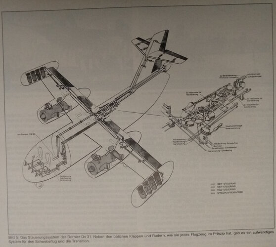
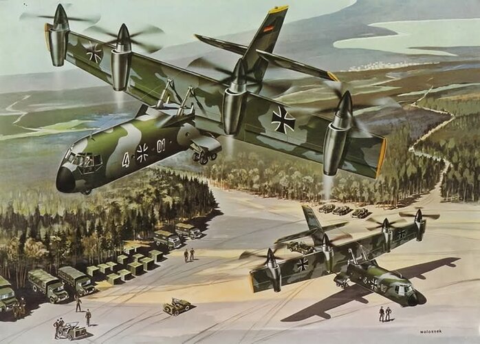
Here a nice video about the Dornier Do 31, but no new information so far.
Code:
https://youtu.be/FM-OOo4Sw-o
https://youtu.be/FM-OOo4Sw-oFrom JAWA 1972.
Good question, but if use the installation in the nose to determine the heightof the lift fans, there would have beenFrom JAWA 1972.
I keep seeing the diagrams of the Do 231M, but I still don't get how the rear cargo door won't clash with the aft series of lift fans???

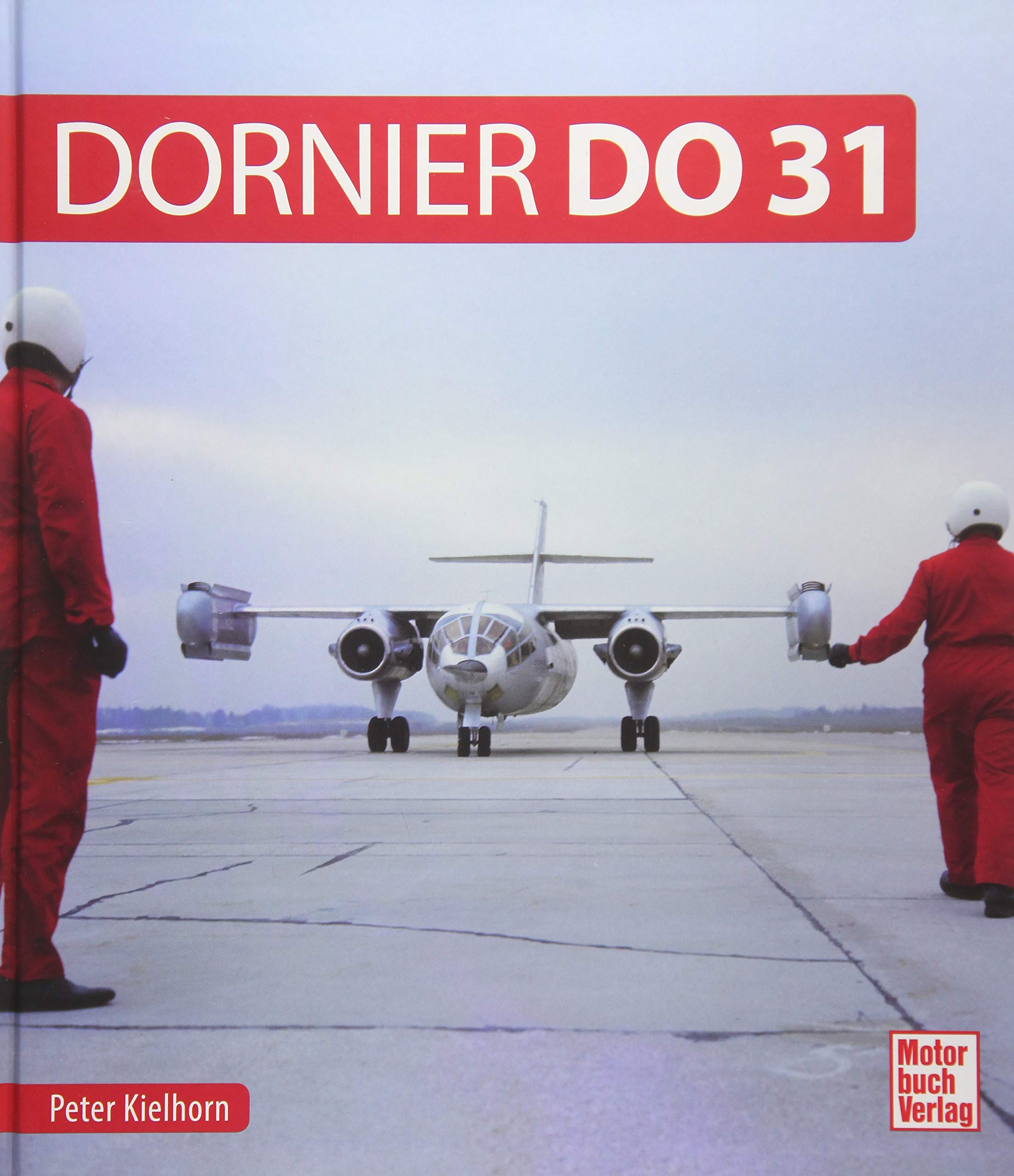
The DoP.333 is new for me...Book I recommend if you are interested int his subject:

Wouldn't this mean split ducts would only be able to work if the doors are closed thoughGood question, but if use the installation in the nose to determine the heightof the lift fans, there would have beenFrom JAWA 1972.
I keep seeing the diagrams of the Do 231M, but I still don't get how the rear cargo door won't clash with the aft series of lift fans???
enough room under them in the tail, I think. Of course, those clamshell doors would have had to be fitted with kind
of split ducts.
View attachment 684090
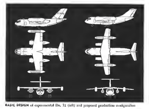
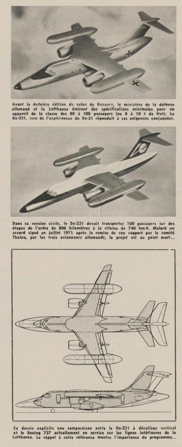
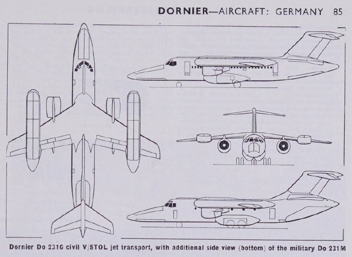
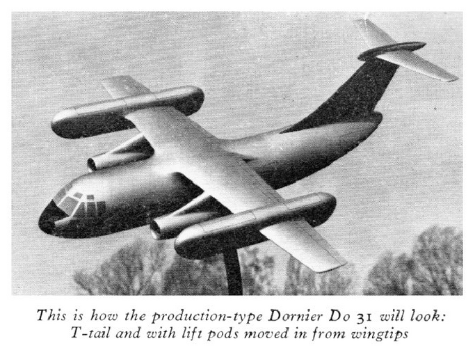
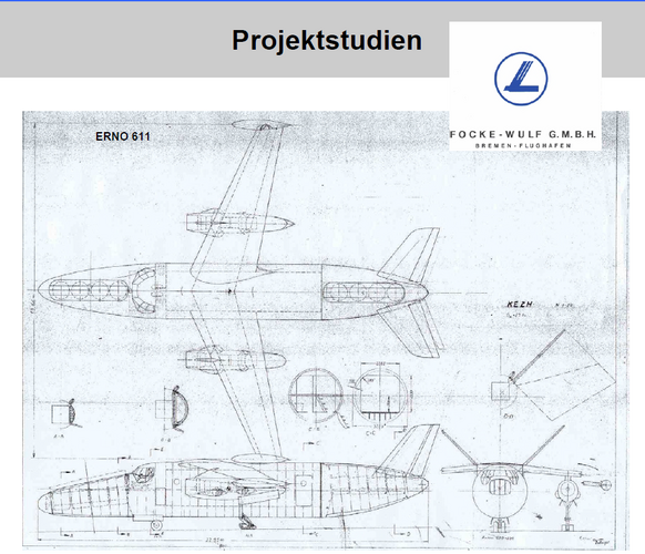
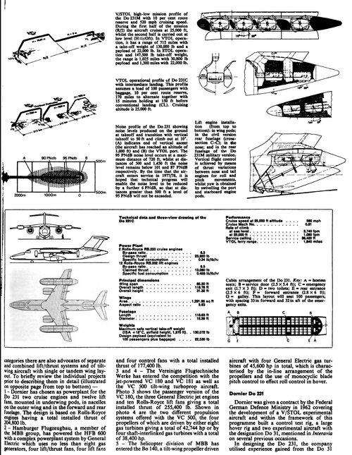
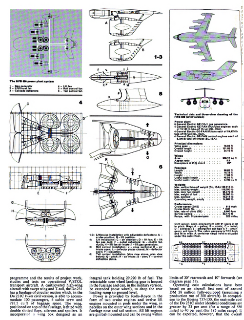
Is there a text in a magazine or website that explains this exact model in the photo of the 31 dornier instead of the E1 prototype?Three-view drawing of Dornier Do 31.
Source: http://aviation-militaire.kazeo.com/Avions-allemands/Dornier-Do-31,a1746673.html
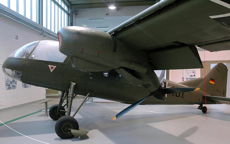
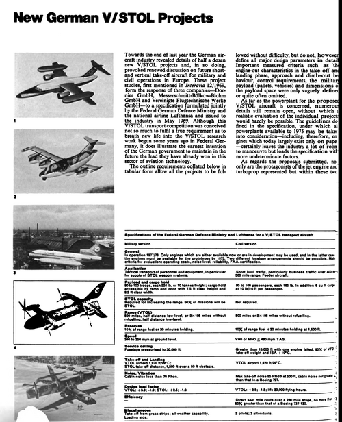
At Dornier the development of the Do 31 was preceded by the Do 29 with an imo far more interesting tilt-rotor design. However concepts like this were unsuccessful because of the limitation of the flight-control systems of the time. Using different engines for hover and forward flight makes this significantly easier.I love how, 50-60 years ago, everyone's solution for vtol was to just put more engines on a frame.
Oh I'm very familiar with the designs. I specialized in this field in university. To this day I'm asked "what's the easiest/cheapest way to make a vtol airplane?" And I always answer "If you want a vtol airplane just add lift engines. There is no solution that is easer and cheaper than that. However, you will pay huge penalties in doing so."At Dornier the development of the Do 31 was preceded by the Do 29 with an imo far more interesting tilt-rotor design. However concepts like this were unsuccessful because of the limitation of the flight-control systems of the time. Using different engines for hover and forward flight makes this significantly easier.
With todays digital fly-by-wire we have options that simply werent realizable back then.
Any chance you could helping out with this earlier thread? I'm still rather perplexed by the Do 231M's rear lift fans...Oh I'm very familiar with the designs. I specialized in this field in university.
Wouldn't this mean split ducts would only be able to work if the doors are closed though
How Dornier's engineers intended to put a rear loading ramp is anyone's guess. All I know about that particular design is that it was intended to have a rear door. Unless they were to extend the lift fans behind the tail, protruding aft from the fuselage, I don't see where the loading ramp would even be connected.Any chance you could helping out with this earlier thread? I'm still rather perplexed by the Do 231M's rear lift fans...
Ah oh well, thanks for trying nonetheless!How Dornier's engineers intended to put a rear loading ramp is anyone's guess. All I know about that particular design is that it was intended to have a rear door. Unless they were to extend the lift fans behind the tail, protruding aft from the fuselage, I don't see where the loading ramp would even be connected.
Sorry I couldn't be of more help.
A delta wing transport? Do you have a picture of it?By the way,Dornier had many projects,based on Do.31,more than which have been displayed here,one
of them has a Delta-Wing.
A delta wing transport? Do you have a picture of it?
How do you know it exists?It's a classified materials.
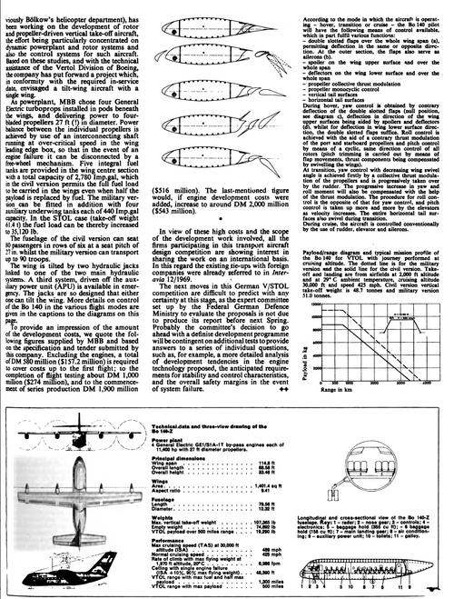
The same picture showing the MBB Bo 140M, but this time without any annoying text overlay from the magazine.Hi,
from Flugzeug Classic 2/2004,here is the Bolkow Bo.140 Model and Bolkow Bo.140M
military version.