
You are using an out of date browser. It may not display this or other websites correctly.
You should upgrade or use an alternative browser.
You should upgrade or use an alternative browser.
Fugaku : Z-plane, G10 or G12
blackkite
Don't laugh, don't cry, don't even curse, but.....
- Joined
- 31 May 2007
- Messages
- 9,408
- Reaction score
- 9,269
Yes. Aichi Denko!Jemiba said:Real designer drawings ? Great find !
The final design actually has a lot of similarities to the B-29 cabin. For the initial
design, a remotely controlled nose turet would be a logical addition. Were such
turrets already then under development in Japan ?
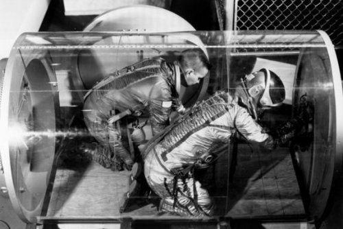
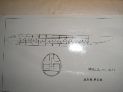
I think this cabin is little small. Where were beds? No beds? But I think this sketch is based on real memory of Fugaku pressurized cabin designer, because AIREVIW magazine is a one of the best, reliable and historic(since 1951)aeronautical magazine in Japan as you know.(same as KOKU FAN magazine)
Mr. Susumu Watanabe was also taking charge of the fitting design of the engine of Kikka.
blackkite
Don't laugh, don't cry, don't even curse, but.....
- Joined
- 31 May 2007
- Messages
- 9,408
- Reaction score
- 9,269
Hi! I think so, too.T-50 said:awsom finds Blackkite san!
so the Fugaku was planned with a B-29 style pressure cabin I presume
anyway its great stuff!!
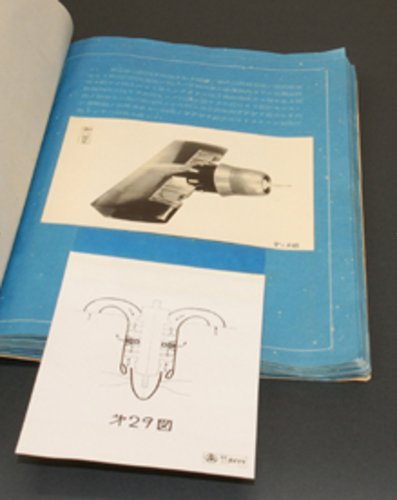
In this magazine, Mr. Watanabe reported that when aerodynamic engineer Yasuo Naito(内藤子生) saw this initial pressurized cabin design, he said “Stop to design such a cabin, it’s like a Japanese spaniel”. Then Mr. Watanabe designed several pressurized cabin shape to match fuselage line, but he could not get clean shape. Finally he designed this final shape.
Mr. Watanabe also reported in this magazine that Fugaku variant which almost finished detail design was only HA-54 engine variant. HA-44 variant and HA-50 variant were only paper plan. Fugaku design team had 200 engineers in Koizumi factory.
The total person in charge of the Fugaku design team was Chief engineer Koyama of the army airplane designing department.
The persons in charge of the aerodynamic design and the performance design were Manager Matsumura of a Navy aircraft designing department, and the Naito engineer.
The person in charge of the body relation design was Manager Fukuda of the Navy aircraft designing department.
The person in charge of the wing design was Manager Shibuya of the army airplane designing department.
The design person in charge of the leg was Manager Ota of the army airplane designing department.
Engineer Dodo took charge of the guess of body weight.
Fuselage cross section was circular same as Renzan.
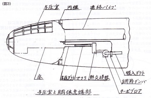
Pressurized cabin inner pressure was same as altitude 3000m atmosphere pressure. Fugaku was planned to have 150×10 litter liquid oxgen bombe to prepare pressurized eqipment malfunction. Mr.Watanabe visited Tachikawa to observe Ki-74 pressurized cabin and oxgen supply system.
Major part detail design of Fugaku and HA-54 engine were finished in June 1944. But Fugaku project was terminated in July 1944.
Attachments
![Yasuo Naito wing aerodynamic designer of Fugaku[1].jpg](/data/attachments/94/94903-f6a6240e0f0ed70bf47ce0202fd6b624.jpg)
blackkite
Don't laugh, don't cry, don't even curse, but.....
- Joined
- 31 May 2007
- Messages
- 9,408
- Reaction score
- 9,269
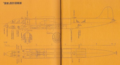
Mr. Watanabe designed the pressurization cabin of Fugaku, repeating trial and error.
About the pressurization cabin of Fugaku, there is some information as follows.
Various designers would limit to memory, seeing the process of trial and error.
(1) The bomb aimer's seat was installed out of the pressurization cabin. (In this case, need airlock, oxgen mask and oxgen bombe for bomb aimer)
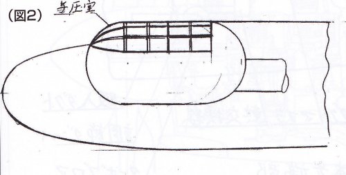
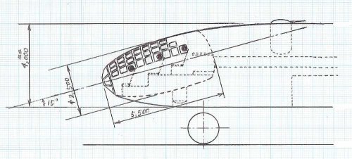
(2) Fugaku had the slanting cocoon type pressurization cabin. (please watch the second picture(my guess))
About (1), if somoone saw the initial design which scolded by the Naito engineer, the possibility that the bomb aimer's seat was installed out of the pressurization cabin exists.
About (2), there may have been such form in process of trial and error.
Fugaku propeller diameter was 4.6m. Number of blades were 8.(constant speed blade). Not contra rotating propeller.
About the pressurization cabin of Fugaku, there is some information as follows.
Various designers would limit to memory, seeing the process of trial and error.
(1) The bomb aimer's seat was installed out of the pressurization cabin. (In this case, need airlock, oxgen mask and oxgen bombe for bomb aimer)
(2) Fugaku had the slanting cocoon type pressurization cabin. (please watch the second picture(my guess))
About (1), if somoone saw the initial design which scolded by the Naito engineer, the possibility that the bomb aimer's seat was installed out of the pressurization cabin exists.
About (2), there may have been such form in process of trial and error.
Fugaku propeller diameter was 4.6m. Number of blades were 8.(constant speed blade). Not contra rotating propeller.
Attachments
blackkite
Don't laugh, don't cry, don't even curse, but.....
- Joined
- 31 May 2007
- Messages
- 9,408
- Reaction score
- 9,269

blackkite
Don't laugh, don't cry, don't even curse, but.....
- Joined
- 31 May 2007
- Messages
- 9,408
- Reaction score
- 9,269
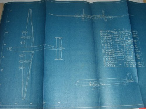
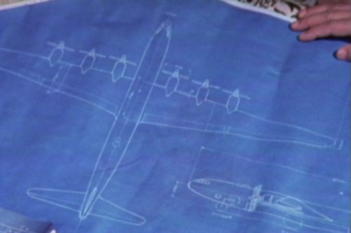
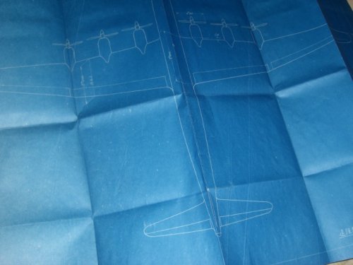
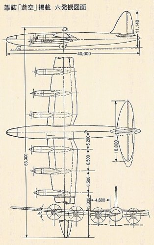
If this plane's size is same as Z-plane, Wing span is 65m, Length is 45m.
I checked the propotion of this drawing and the result is good. Pressurized cabin root diameter is about 2.4 to 2.5m, not bad.
Maximum fuselage dialeter is about 3.9 to 4.0m, not bad. But wing area is about 410 square meter. Z-planes wing area is 350 square meter. 410 square meter is about 17% large. I think 410 square meter is little large for Fugaku.
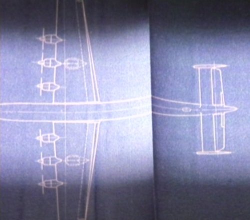
Wing and horizontal tail stabilizer trailing edge have interesting curved shape. Bubble windshield for turrets are too large.
I checked the propotion of this drawing and the result is good. Pressurized cabin root diameter is about 2.4 to 2.5m, not bad.
Maximum fuselage dialeter is about 3.9 to 4.0m, not bad. But wing area is about 410 square meter. Z-planes wing area is 350 square meter. 410 square meter is about 17% large. I think 410 square meter is little large for Fugaku.
Wing and horizontal tail stabilizer trailing edge have interesting curved shape. Bubble windshield for turrets are too large.
Attachments
- Joined
- 11 March 2006
- Messages
- 8,491
- Reaction score
- 4,740
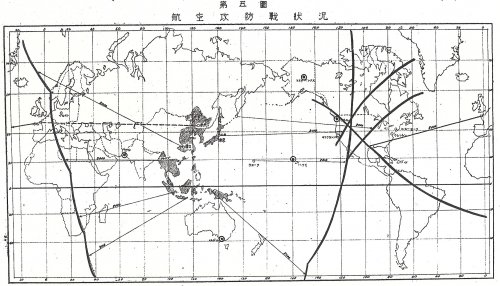
Having read the very interesting article "The Japanese Giants" from Airpower, July 1981 issue (thank you, Paul !), it's
mentioned there, that Fugaku was intended to conduct, what the allies called "shuttle bombing", taking of in Japan and
landing in Germany, after attacking the USA. Have searched this thread, but didn't found it mentioned till now. Is this
mentioned anywhere else ? Planning such a mission, certainly would have needed close cooperation with Germany and
at best from the start.
- Joined
- 11 March 2006
- Messages
- 8,491
- Reaction score
- 4,740
Well, that was my first reaction, too. A quick look on the map nevertheless shows, that theblackkite said:Hmmm.....
distance Japan-USA to USA-Germany is about the relation 1:0.75. And the estimated/demanded
range of Fugaku (10,000 nm) may have been regarded as quite optimistic by Japanese officials
back then, too. So this could have been regarded as a way to reach the target nevertheless,
without conducting a one-way mission from the start.
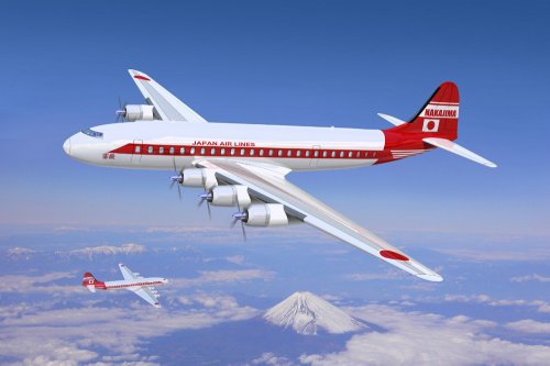
awsome art work you have posted Blackkite San!blackkite said:Hi! Another image.
blackkite
Don't laugh, don't cry, don't even curse, but.....
- Joined
- 31 May 2007
- Messages
- 9,408
- Reaction score
- 9,269
I think that it is better to arrange the right information about Z/Fugaku project once in this time.
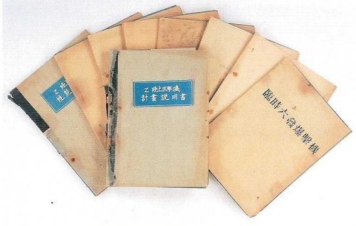
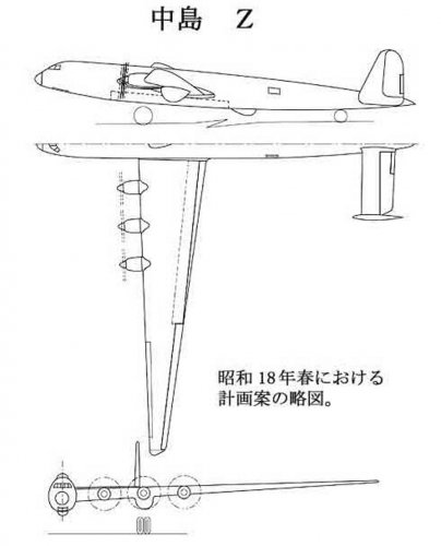
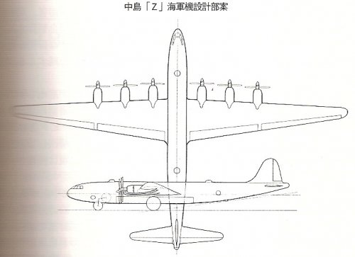
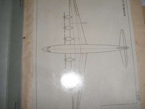
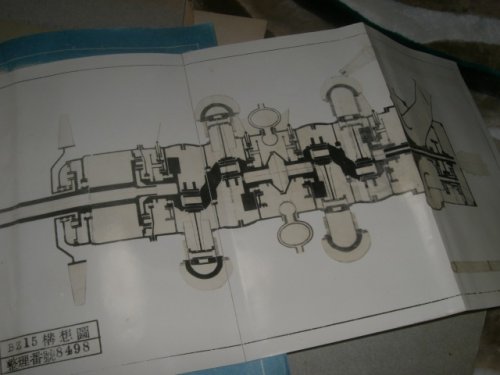
At first Z-Ohta official drawing.
But this drawing might be a 6×HA-44 engine(take off power 2400hp) temporary bomber which was designed by Ohta factory. Propeller seems to be single type instead of contra rotating type.
I believe that the shape of Z-Ohta and Ohta factory designed temporary 6 engine bomber were same withput engine.
The development of HA-54 engine(take off power 5000hp) was not on time at the day.
臨時六発爆撃機 means temporary 6 engine bomber.
昭和18年春における計画案の略図 means simplified drawing of the plan in spring 1943.
Z陸上攻撃機計画説明書 : Z-land base attack aircraft plan explanation.
性能(計算書) : Performance (culculation sheet)
Attachments
blackkite
Don't laugh, don't cry, don't even curse, but.....
- Joined
- 31 May 2007
- Messages
- 9,408
- Reaction score
- 9,269
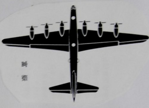
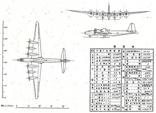
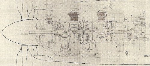
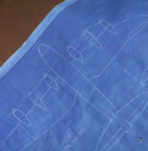
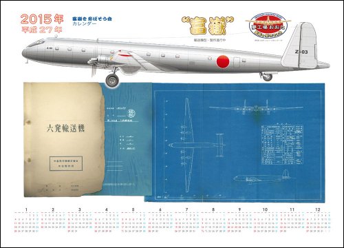
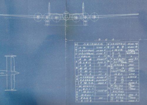
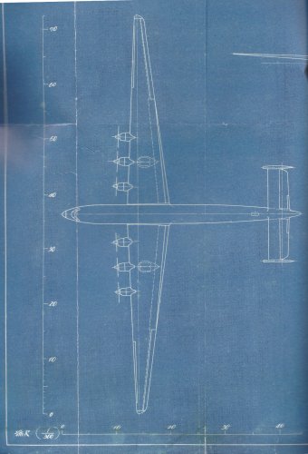
I believe these drawings are the traced one based on Nakajima Koizumi factory's official drawing which survived still now.
This design had turbo charged 36 cylinders HA-54 engine, contra rotating propeller, middle engine nacelle installed drop tire and remote control turrets.
This design had turbo charged 36 cylinders HA-54 engine, contra rotating propeller, middle engine nacelle installed drop tire and remote control turrets.
Attachments
blackkite
Don't laugh, don't cry, don't even curse, but.....
- Joined
- 31 May 2007
- Messages
- 9,408
- Reaction score
- 9,269
blackkite
Don't laugh, don't cry, don't even curse, but.....
- Joined
- 31 May 2007
- Messages
- 9,408
- Reaction score
- 9,269
blackkite
Don't laugh, don't cry, don't even curse, but.....
- Joined
- 31 May 2007
- Messages
- 9,408
- Reaction score
- 9,269

- Joined
- 26 May 2006
- Messages
- 37,557
- Reaction score
- 19,598
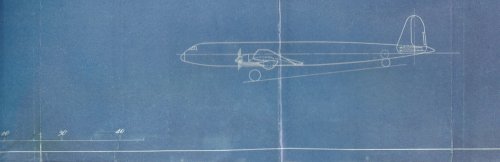
blackkite said:Z-transport designed by Nakajima Ohta factory. It had sweep back wing leading edge. You already know flying model of this plane.
That's nice my dear Blackkite.
blackkite
Don't laugh, don't cry, don't even curse, but.....
- Joined
- 31 May 2007
- Messages
- 9,408
- Reaction score
- 9,269
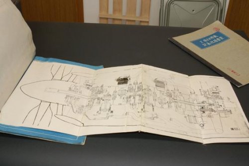
And Fugaku. We can't find Fugaku official drawing still now. But recentry we get Fugaku pressurized cabin sketch which is made by it's designer Mr. Watanabe.
Mr.Watanabe also reported that
(1) Fugaku propeller diameter was 4.6m. Number of blades were 8.(constant speed blade). Not contra rotating propeller.
(2) Fugaku variant which almost finished detail design was only HA-54 engine variant.
(3) HA-44 variant and HA-50 variant were only paper plan.
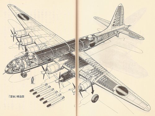
(4) Fugaku's HA-54 engine had a single stage 3 speed mechanical supercharger.(HA-54 did not have turbo charger.)
(5) Fugaku fuselage cross section was circular same as Renzan.
(5) Main landing gear tire diameter was 1.9m, breadth was 0.5m, weight was 1ton. There were two tires in each landing gear, inner tire was dropped just after take off.
(6) Main wing had thick plate box beam structure(upper and lower skin plate, front girder and aft girder) which withstand bending moment and torsion, leading and trailing edge was made by thin plate, same as recent airliner.
http://www.secretprojects.co.uk/forum/index.php/topic,14582.225.html
Mr.Watanabe also reported that
(1) Fugaku propeller diameter was 4.6m. Number of blades were 8.(constant speed blade). Not contra rotating propeller.
(2) Fugaku variant which almost finished detail design was only HA-54 engine variant.
(3) HA-44 variant and HA-50 variant were only paper plan.
(4) Fugaku's HA-54 engine had a single stage 3 speed mechanical supercharger.(HA-54 did not have turbo charger.)
(5) Fugaku fuselage cross section was circular same as Renzan.
(5) Main landing gear tire diameter was 1.9m, breadth was 0.5m, weight was 1ton. There were two tires in each landing gear, inner tire was dropped just after take off.
(6) Main wing had thick plate box beam structure(upper and lower skin plate, front girder and aft girder) which withstand bending moment and torsion, leading and trailing edge was made by thin plate, same as recent airliner.
http://www.secretprojects.co.uk/forum/index.php/topic,14582.225.html
Attachments

blackkite
Don't laugh, don't cry, don't even curse, but.....
- Joined
- 31 May 2007
- Messages
- 9,408
- Reaction score
- 9,269
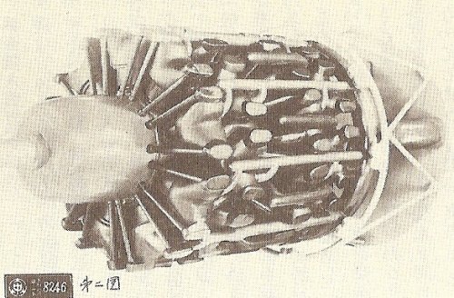
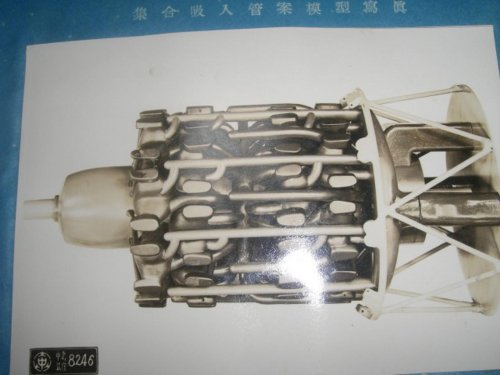
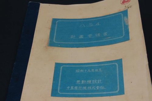
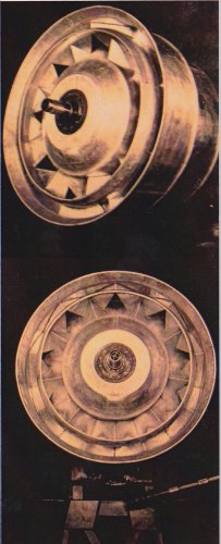
Hi! HA-54 engine official documents. These document clearly shows that HA-54 had a single propeller, did not have a contra rotating propeller.
"ハ54計画要領書" means HA-54 engine plan point document.
"昭和19年4月" means April of 1944.
"発動機設計" means engine design.
"中島飛行機株式会社" means Nakajima aircraft Co, Ltd.
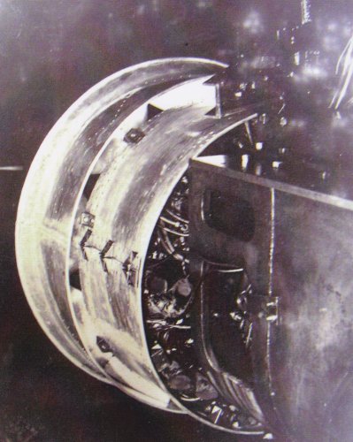
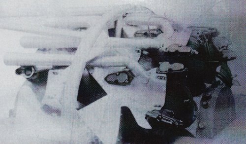
"集合吸入管案模型写真" means engine inlet air piping and manifold plan model picture.
http://www.fukuya-works.com/html/others-c.htm
"ハ54計画要領書" means HA-54 engine plan point document.
"昭和19年4月" means April of 1944.
"発動機設計" means engine design.
"中島飛行機株式会社" means Nakajima aircraft Co, Ltd.
"集合吸入管案模型写真" means engine inlet air piping and manifold plan model picture.
http://www.fukuya-works.com/html/others-c.htm
Attachments
-
 HA54 MODEL.jpg129.7 KB · Views: 70
 -
 HA-54 MOCKUP.jpg108.3 KB · Views: 64
 -
 enigne mockup.jpg91.8 KB · Views: 70
 -
 HA-54 plan point document 5.jpg162.1 KB · Views: 74
 -
 HA-54 plan point document 4.jpg772.1 KB · Views: 62
 -
 HA-54 plan point document 3.jpg93.7 KB · Views: 58
 -
 HA-54 plan point document 2.jpg25.2 KB · Views: 55
 -
 HA-54 plan point document 1.jpg17.1 KB · Views: 524
 -
 Cover of HA-54 engine plan point document.jpg17.9 KB · Views: 531
blackkite
Don't laugh, don't cry, don't even curse, but.....
- Joined
- 31 May 2007
- Messages
- 9,408
- Reaction score
- 9,269
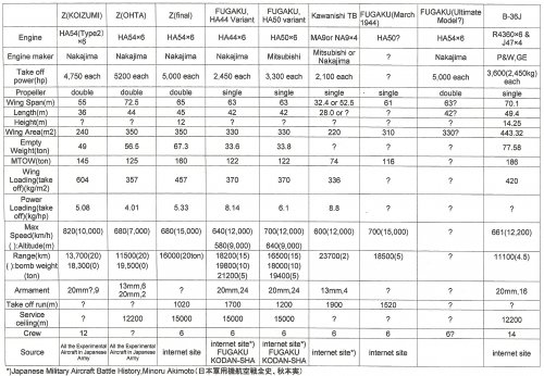
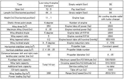
Fugaku's specification was as follows? (Same as Z-plane?)
Wing span:65m, Overall length:45m, Wing area:350m2, MTOW:160ton, Engine power:30,000HP(5,000HP × 6), Max speed:680km/h, Range:16,000km with 20 ton bomb.
Fugaku's engine was Nakajima HA54(called as BZ in Nakajima) aircooling 4 array radial 36 cylinders(18 cylinders ×2), cylinder diameter:146mm, stroke:160mm, Displacement : 96.4L, with single stage 3 speed mechanical super charger, cowling outer diameter:1,550mm, Overall length:3,581mm, Dry weight:2,450kg,
5,000HP in take off, supercharger first speed, 2800rpm,boost +600mmHg, altitude 0m,
4,300HP supercharger second speed, 2800rpm, boost +400mmHg, altitude 0m,
4620HP, supercharger second speed, 2800rpm, boost +400mmHg, altitude 2200m,
4060HP, supercharger third speed, 2800rpm, boost +400mmHg, altitude 6300m
The chief engineer of HA54 was Kiyoshi Tanaka(田中清史),who had the carrier of Mamoru(護) engine chief engineer,the largest engine that Nakajima ever built.(double 14 cylinder air cooling engine).HA54 design team was consisted of 50 engineers.
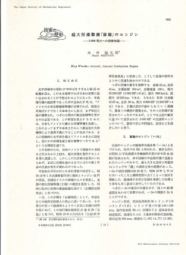
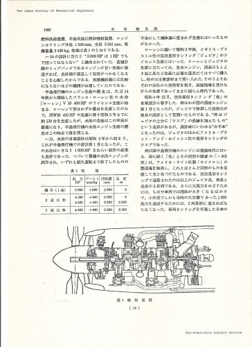
The evidence of these information is attached paper by Nakajima's engineer Mr.Sotaro Mizutani.(水谷総太郎) : Nakajima airplane incorporated company Ogikubo factory Experiment part The first experiment section chief (at the day)
Wing span:65m, Overall length:45m, Wing area:350m2, MTOW:160ton, Engine power:30,000HP(5,000HP × 6), Max speed:680km/h, Range:16,000km with 20 ton bomb.
Fugaku's engine was Nakajima HA54(called as BZ in Nakajima) aircooling 4 array radial 36 cylinders(18 cylinders ×2), cylinder diameter:146mm, stroke:160mm, Displacement : 96.4L, with single stage 3 speed mechanical super charger, cowling outer diameter:1,550mm, Overall length:3,581mm, Dry weight:2,450kg,
5,000HP in take off, supercharger first speed, 2800rpm,boost +600mmHg, altitude 0m,
4,300HP supercharger second speed, 2800rpm, boost +400mmHg, altitude 0m,
4620HP, supercharger second speed, 2800rpm, boost +400mmHg, altitude 2200m,
4060HP, supercharger third speed, 2800rpm, boost +400mmHg, altitude 6300m
The chief engineer of HA54 was Kiyoshi Tanaka(田中清史),who had the carrier of Mamoru(護) engine chief engineer,the largest engine that Nakajima ever built.(double 14 cylinder air cooling engine).HA54 design team was consisted of 50 engineers.
The evidence of these information is attached paper by Nakajima's engineer Mr.Sotaro Mizutani.(水谷総太郎) : Nakajima airplane incorporated company Ogikubo factory Experiment part The first experiment section chief (at the day)
Attachments
blackkite
Don't laugh, don't cry, don't even curse, but.....
- Joined
- 31 May 2007
- Messages
- 9,408
- Reaction score
- 9,269
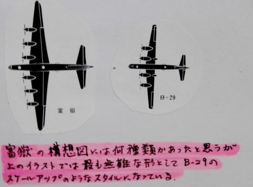
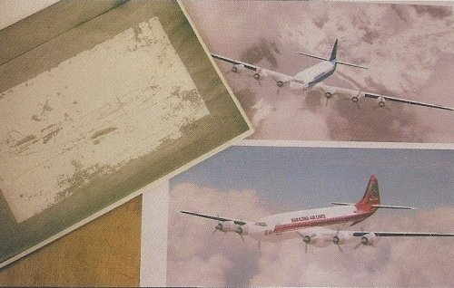
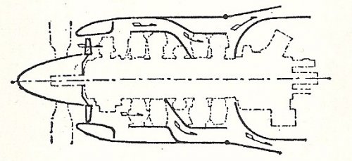
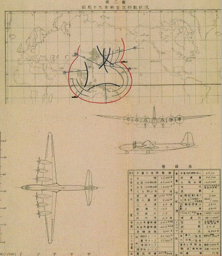
In the Fugaku committee, the proposal of various airplanes was shown and confusion arose. (by Sotaro Mizutani)
The plan shown in following drawings may also be one of them.
Top one might be a Kawanishi plan as some one said. Bottom one's tail stabilizer horizontal shape looks like Mitsubishi Ki-67's one.
Kawasaki concentrated Ki-91 and Tachikawa concentrated Ki-74 at the day.
The plan shown in following drawings may also be one of them.
Top one might be a Kawanishi plan as some one said. Bottom one's tail stabilizer horizontal shape looks like Mitsubishi Ki-67's one.
Kawasaki concentrated Ki-91 and Tachikawa concentrated Ki-74 at the day.
Attachments
- Joined
- 11 March 2006
- Messages
- 8,491
- Reaction score
- 4,740
Wing and tailplane shape of the design in the first and third picture reminds me o
the He 111, in which Japan was interested before the war, IIRC, but never got them.
Nevertheless, plans and even the original may well have been known after losses of the
Chinese airforce in the Sino-Japanese war.
the He 111, in which Japan was interested before the war, IIRC, but never got them.
Nevertheless, plans and even the original may well have been known after losses of the
Chinese airforce in the Sino-Japanese war.
blackkite
Don't laugh, don't cry, don't even curse, but.....
- Joined
- 31 May 2007
- Messages
- 9,408
- Reaction score
- 9,269
Hi!
http://www.doujinpress.com/products/50635~040030036489/
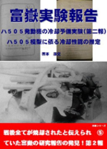
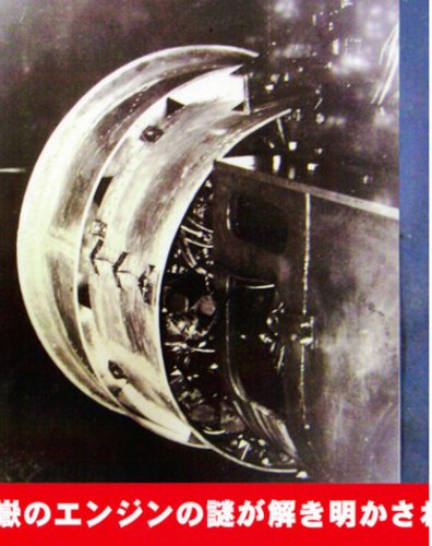
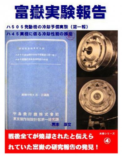
There were four reports for HA-54(HA-505) preliminary cooling performance test.
I got No.1 and No.2 report. According to No.2 report, test result was not sufficient, especiall the fourth row cylinder cooling, need modification for cooling air buffle shape. I will try to get No.3 and No.4 report.
http://www.doujinpress.com/products/50635~040030036489/
There were four reports for HA-54(HA-505) preliminary cooling performance test.
I got No.1 and No.2 report. According to No.2 report, test result was not sufficient, especiall the fourth row cylinder cooling, need modification for cooling air buffle shape. I will try to get No.3 and No.4 report.
Attachments
blackkite
Don't laugh, don't cry, don't even curse, but.....
- Joined
- 31 May 2007
- Messages
- 9,408
- Reaction score
- 9,269
blackkite
Don't laugh, don't cry, don't even curse, but.....
- Joined
- 31 May 2007
- Messages
- 9,408
- Reaction score
- 9,269
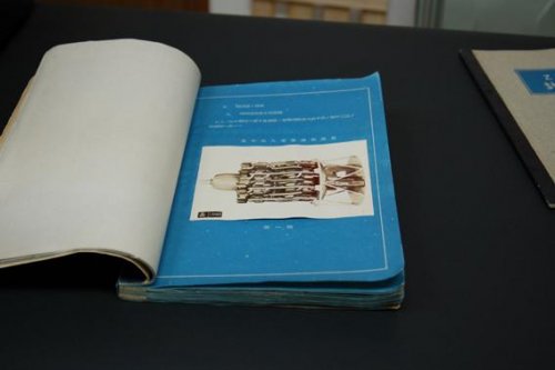
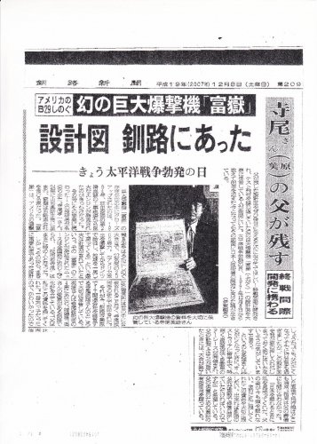
Hi! Hokkaido Kushiro news paper in 8/12/2007.
There was Fugaku design drawings in Hokkaido Kushiro city in 8/12/2007.
The plan (equipment figure) of Fugaku was kept by the designer's son, without being known by the world.
The designer's son is wishing effective use of the plan.
I'm contacting to the designer's son now.
There was Fugaku design drawings in Hokkaido Kushiro city in 8/12/2007.
The plan (equipment figure) of Fugaku was kept by the designer's son, without being known by the world.
The designer's son is wishing effective use of the plan.
I'm contacting to the designer's son now.
Attachments
good work Blackkite san to contact the son of the designer! its already very interesting stuff you send us!blackkite said:Hi! Hokkaido Kushiro news paper in 8/12/2007.
There was Fugaku design drawings in Hokkaido Kushiro city in 8/12/2007.
The plan (equipment figure) of Fugaku was kept by the designer's son, without being known by the world.
The designer's son is wishing effective use of the plan.
I'm contacting to the designer's son now.
thanks
- Joined
- 11 March 2006
- Messages
- 8,491
- Reaction score
- 4,740
Hopefully he isn't one of those "smart business" men, just trying to make the best of
those documents, although it would be somewhat understandable, I must say. A lot
of original docs, drawings and photos are said to have been vanishing into collections,
with their owners not having the slightest interest in making them public, not as books
or otherwise. :-[
those documents, although it would be somewhat understandable, I must say. A lot
of original docs, drawings and photos are said to have been vanishing into collections,
with their owners not having the slightest interest in making them public, not as books
or otherwise. :-[
blackkite
Don't laugh, don't cry, don't even curse, but.....
- Joined
- 31 May 2007
- Messages
- 9,408
- Reaction score
- 9,269
blackkite
Don't laugh, don't cry, don't even curse, but.....
- Joined
- 31 May 2007
- Messages
- 9,408
- Reaction score
- 9,269

Kevin Renner
ACCESS: Confidential
- Joined
- 6 November 2007
- Messages
- 104
- Reaction score
- 14
I have wonder. Just where did the IJA/N ever think they would get the fuel for such a beast


thonthon42
ACCESS: Restricted
- Joined
- 21 December 2008
- Messages
- 15
- Reaction score
- 2
Success and Merry Christmas
[/quote]
Very impressive, the drawings and subjects !
@+++
Tonton
[/quote]
Very impressive, the drawings and subjects !
@+++
Tonton
Similar threads
-

-

-
-
 Nakajima Ki-49 Donryu (Helen) special versions
- Started by Temistocle
- Replies: 15
-
Japanese jet transports and bombers in 1940s?
- Started by Norse
- Replies: 24