blackkite
Don't laugh, don't cry, don't even curse, but.....
- Joined
- 31 May 2007
- Messages
- 8,819
- Reaction score
- 7,716
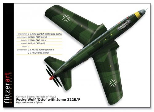
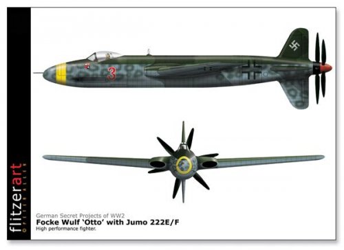
Thank you so much Robin and Jens!robunos said:Blackkite, I think you're right about the cooling air exit, and I've just found this, from Putnam's 'McDonnell Douglas' Volume 1, page 363;
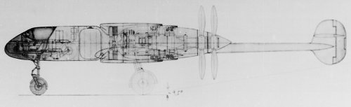
"The laminar-flow wing with double slotted flaps housed the fuel tanks and the oil and coolant radiators which were fitted with ground cooling fans."
Later, on page 363-4, it says this; "...limited efficiency of the cooling ducts. Solutions...were found relatively quickly..."
I think these fans would have to have been driven electrically, and not directly off the engines.
cheers,
Robin.
")
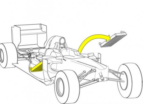
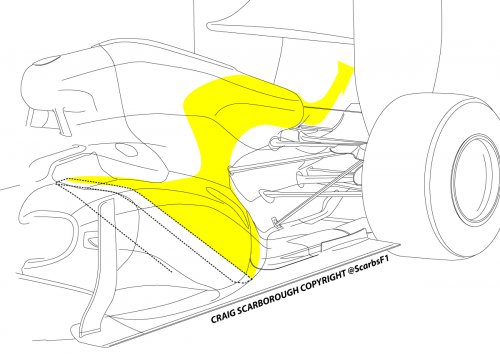
Don't feel so sad Jens. Never mind. F1 car has no fan.