
You are using an out of date browser. It may not display this or other websites correctly.
You should upgrade or use an alternative browser.
You should upgrade or use an alternative browser.
EWR VJ-101A/B/C/D/E VTOL fighter projects
- Thread starter Thorvic
- Start date
- Joined
- 27 December 2005
- Messages
- 17,748
- Reaction score
- 26,408
A72-19250 V/STOL-weapon system VJ-101. II - VJ101A+B (V/STOL-Waffensystem VJ-101. II - VJ-101A+B). H.
Redemann.
Flug Revue/Flugwelt International, Feb. 1972, p. 35-39.
In German.
The models VJ-101A and VJ-101B were independently developed by the two German aerospace companies, Heinkel and Messerschmitt. The VJ-101A was the last version of the He231. The VJ-101A6 was equipped with six propulsive units of the type Rolls-Royce RB.153. The propulsion units were aligned in a vertical direction for the takeoff, and subsequently brought into normal position. The P1227 project of the Messerschmitt company involved a design with a delta wing. An evaluation of the designs for the VJ-101 A and the VJ-101B models led to plans for the development of the VJ-101C model. G.R.
A72-19251 V/STOL weapon system VJ-101. I - Heinkel He231 (V/STOL-Waffensystem VJ-101. I - He231). H. Redemann.
Flug Revue/Flugwelt International, Nov. 1971, p. 18-22.
In German.
The history of the Heinkel He231 began in December 1957 when the German Ministry of Defense sent out requests of proposals to the industry for an all-weather fighter with V/STOL capabilities.A number of different designs were worked out by the Heinkel design team. The designs are discussed and a number of design sketches are presented. In February 1959 an organization for the further development of the fighter was founded by the aerospace companies Heinkel, Messerschmitt, and Bolkow.
For anyone in possession of Flug Revue, two article references.
Source:
Aeronautical Engineering: A special bibliography with indexes, supplement 18, May 1972 - NASA Technical Reports Server (NTRS)
This special bibliography lists 367 reports, articles, and other documents introduced into the NASA scientific and technical information system in April 1972.
- Joined
- 27 December 2005
- Messages
- 17,748
- Reaction score
- 26,408
As far as I know, no, EWR moved reasonably quickly onto the VJ-101E with Boeing, which became the AVS.So far nothing has been published about wherher any work was done on the two prototypes of the VJ101D.
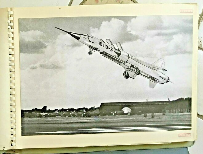
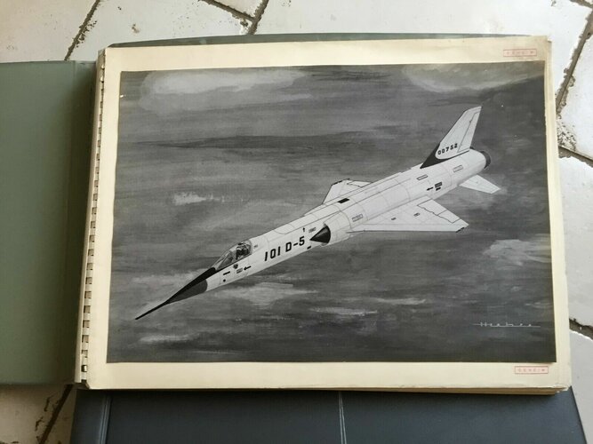
It is perhaps significant that the final drawing published and the only model shows a very TSR2 like aircraft.
- Joined
- 26 May 2006
- Messages
- 34,895
- Reaction score
- 15,759
As far as I know, no, EWR moved reasonably quickly onto the VJ-101E with Boeing, which became the AVS.
Not so quickly my dear PaulMM,
the EWR began to develop 101D from exactly mid 1961,and in 1963 changed a little bit in lift fan configuration,
then in early months of 1964,moved to 101E AVS.
- Joined
- 27 December 2005
- Messages
- 17,748
- Reaction score
- 26,408
Original article from Klassiker is available here:

 www.flugrevue.de
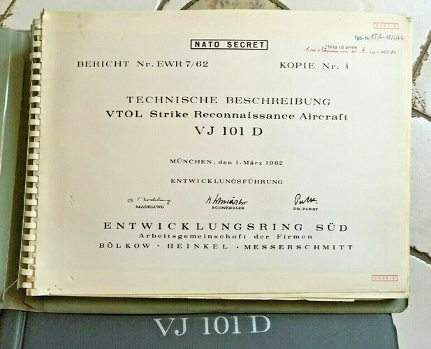
Kampfflugzeug EWR VJ 101
Im Februar 1959 schlossen sich die Firmen Bölkow, Heinkel und Messerschmitt zur Arbeitsgemeinschaft Entwicklungsring Süd GmbH zusammen, um gemeinsam ein Hochleistungs-Kampfflugzeug mit VTOL-Eigenschaften zu entwickeln, das Projekt EWR VJ 101.
www.flugrevue.de
EWR VJ 101 - All variants part 1
The Heinkel company brought an aircraft project with vertical take-off characteristics into this community, which later went under the name VJ 101 A. The Messerschmitt company introduced the type VJ 101 B.
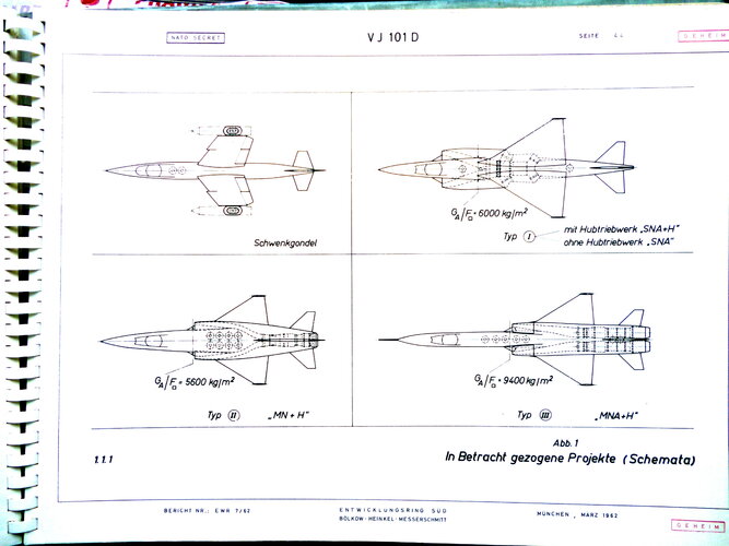
From these 2 basic models, the VJ 101 C was later developed in the working group and continued until the construction of 2 experimental aircraft. The VJ 101 D as a successor model represents the development of an operational VTOL fighter aircraft. This series of investigations was canceled in the summer of 1964 in favor of a more advanced concept. As can be seen from Figures 1 to 3, numerous variants were examined. This compilation contains around 70 aircraft designs. Due to the design studies, some of which were very distant, it was very difficult to collect extensive and complete documents. It must therefore be said that this compilation cannot claim to be complete.
VJ 101 A (illustration 4)
The starting point for the VJ 101 A was the idea of not providing separate engines for the VTOL phase. These lift-cruise engines, which are not operational during aerodynamic flight, add weight, which reduces payload. The fully pivoting lift-and-marsh engines are mounted on booms or on the wings. Control during the VTOL phase is carried out using thrust modulation. During the cruise phase, the excess thrust of the 6 engines is significant. In the VTOL phase, however, the failure of one of the front engines can lead to an immediate crash. As can be seen from Figure 4, this concept shows a simple structural design for the aircraft fuselage. The engine mounting in the wing and on the front engine mounts, on the other hand, meant new developments.
Technical data:
6 x RB 153 with afterburner VTO: weight approx. 9,600 kg
VJ 101 B (illustration 5-9)
The VJ 101 B according to Figure 5 was from the Messerschmitt company was brought into the EEA working group. This aircraft weighed around 7,000 kg and had type RB 153 lift-and-marsh engines and one type RB 162 lift-and-run engine. The VTOL control was carried out via reaction nozzles using bleed air from the lift-and-run cruise engines.
Illustration 6 shows a simplified draft of illustration 5. This is the design of an experimental aircraft for testing purposes. Since this aircraft is designed to be significantly lighter, 2 lift-cruise engines and 1 lift engine were sufficient (illustrations 7 and 8).
These types represent a larger aircraft than the type in Figure 5. For this reason, a lifting engine was installed in addition to the existing engines. The difference in the arrangement can be seen from the illustrations.
Figure 9 shows a draft with a fundamental change to the engine concept. While the lifting thrust was previously oriented around the center of gravity, two engine groups can be identified in this study. Behind the cockpit there are two pure lift engines, while the exit of the lift-marsh engines for the VTOL phase has been moved far into the rear of the fuselage. The underside of the fuselage around the center of gravity remains free for weapons loads.
Rocker for VJ 101 C development (illustration 10)
The rocker was built as the first experimental device to test pure thrust control, as was the basis for the conception of the later VJ 101 C experimental aircraft. It is designed in such a way that the thrust effect on the movements of the pitch or roll axis corresponds to that in the planned aircraft, depending on the test arrangement. Thanks to their positive results, the tests created the conditions for continuing the development of the VJ 101.
This simple device was able to be experimented with as early as May 1960; The controls in the pitch and roll axes were tested by hand and then various autopilots were tested.
The rocker is essentially a horizontal beam that is supported at one end while the other end is free to rock up and down. An RB 108 engine is mounted on this rocker beam in such a way that its thrust reaches the free-swinging beam end ch moved above.
In the rest position, the rocker beam is locked in the horizontal position by a support. When “starting” the pilot releases this lock. A “flight” consists of lifting off the rocker beam using engine thrust. The thrust is adjusted up to 80% using the throttle lever; Fine adjustment of up to +20% is carried out via the control stick, resulting in a thrust modulation range of 60-100%.
The control is designed so that the rocker bar remains in balance when the throttle is fully open and the stick is at zero. There is still room for an upward deflection from floating to maximum thrust.
Control deflections are possible between + 5 and + 15o to the zero position. The freedom of movement is limited by two shock absorbers in front of and behind the pivot point of the rocker and can be fixed in the area mentioned.
Two different arrangements are planned for the control tests: For pitching exercises, the pilot's seat is mounted on the free end of the beam, directly in front of the engine, which functions as the fuselage engine; In this way, the movements of the planned aircraft around its transverse axis can be simulated using the rocker beam.
For roll exercises, only the position of the pilot's seat is changed; it is arranged on a side extension in an extension of the pendulum axis. The engine now functions as a wing engine. In this way, the movements of the planned aircraft around its longitudinal axis can be simulated using the rocker beam.
Technical data:
Length of pitch arrangement: 6,330 mm
Roll arrangement:
5,000mm
Wide pitch arrangement: 3,200 mm
Roll arrangement: 3,500 mm
Height:
3,800mm
Engine: 1 Rolls Royce RB 108
Max. engine thrust: 950 kp
Fuel tank volume (1 container): approx. 520 l
Hover thrust: approx. 750 kp
Fuel consumption: 1.05 kp/kp.h
Maximum flight time in hovering state: 15 - 20 min
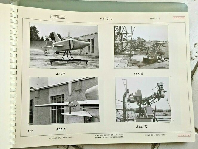
Floating frame for the VJ 101 C development (illustration 11)
The floating frame was created as a simulation device for the VJ 101 C during its development. Its geometry was designed according to the conception of the future test aircraft. This meant that direct conclusions could be drawn from the test results about the behavior of the later aircraft. Such an experimental device enables significant savings in time, money and risk.
Since 1961, the following have been tested with the hover frame: vertical takeoff and landing, hovering flight, control in all three axes and altitude maintenance. The control movements are carried out by changing the thrust (thrust modulation) and - during yaw - by pivoting the wing engines and can be carried out both by hand and with automatic control (autopilot). That's why the hover frame also provides excellent services for the training and retraining of test pilots for the VJ 101 C.
The tubular steel fuselage of the hover frame (with side booms), which is uncovered for better access to all units, carries - at the same distances from the center of gravity as the planned aircraft - three RB 108 engines: two at the "wing" ends and one in the fuselage, in front of it the pilot's seat. The landing gear also corresponds to that of the aircraft in terms of track width, wheelbase and position relative to the center of gravity. The controls are the same.
In the first tests, the floating frame was "tied", i.e. its center of gravity was supported on an extendable column using a cardan joint. In March 1962 it flew freely for the first time, after taking off vertically from a concrete slab. To research the influences on the ground, a sail was stretched under the fuselage, from the vertical stabilizer to the side engine, which simulates the effect of the wings. The results are excellent: in every control function, not only manually but also via autopilot, this experimental device fulfills all its tasks.
Technical data:
Length: 11,500mm
Width: 10,200mm
Height: 3,250mm
Engines: 3 Rolls Royce RB - 108
Max. thrust per engine: 950 kp
Fuel tank volume (2 containers): approx. 900 l
Max. take-off weight including fuel (545 kg): 2,400 kg
Fuel consumption: 1.05 kp/kp.h
Maximum flight time (10% fuel reserve): approx. 12 min
EWR VJ 101 - All variants part 2
In both samples the cell consisted primarily of light metal; However, steel and titanium were used in particularly hot areas near the engine. Photo and copyright: Development Ring Süd GmbH
21 PICTURES
VJ 101 C-X 1 AND -X2 (illustration 12 to 14)
The evaluation of the investigations on the project studies VJ 101 A and VJ 101 B led to the design VJ 101 C. This configuration - shoulder-wing aircraft with slightly swept wings and a twin-engine nacelle each and two lifting engines in the front fuselage - best met the requirements of an interceptor the speed class Mach 2. The reasons for this engine arrangement were as follows:
a) The entire power (including afterburner thrust) is available for vertical takeoff and landing
b) No thrust losses due to beam deflection
c) VTOL control is by thrust modulation, therefore no control nozzles are required
d) Since the lifting cruise engines and their air inlets are not installed in the fuselage, this results in a simple structural design of the cell with a relatively low construction weight.
After extensive measurements in subsonic and supersonic channels to determine the aerodynamic properties, the construction of 2 test aircraft began: the VJ 101 C-X1 and -X2. The X2 differs from the Mach 1.8 allowed.
In both models, the cell is primarily made of light metal; However, steel and titanium are used in particularly hot areas near the engine. The design of the air inlets for the lifting engines around the fuselage and the slewing engines on the wings required great attention. During normal flight, the inlets of the two lifting engines were covered by a simple flap that is opened during takeoff and landing. The additional inlets to the lifting cruise engines were designed in the form of a slot that runs around the entire nacelle and which is released by pushing the entire inlet part forward.
Even with large oblique blowing, these slots result in a satisfactory pressure distribution at the engine inlet. The flight experiences with the X1 and X2 brought valuable insights into specific problems such as VTOL control and recirculation of the hot exhaust jets.
Milestones in the development of the VJ 101 C were:
- November 2, 1956: “Interceptor” project competition by the Federal Minister of Defense
- September 29, 1959: Decision for VJ 101 - Solution C
- May 10, 1960: Start of tests on the seesaw
- May 3, 1961: Start of tests on the column with a floating frame
- May 13, 1962: First hovering flight with the hover frame
- December 19, 1962: Start of tests on the tripod with the now completed VJ 101 C-X1
- April 10, 1963: First hover flight of the VJ 101 C-X1
- August 31, 1963: First aerodynamic flight of the VJ 101 C-X1
- September 20, 1963: First separate take-off and landing transition of the VJ 101 C-X1
- October 8, 1963: First complete transition of the VJ 101 C–X1
- 23.4. - May 3, 1964: On the occasion of the air show in Hanover, six transition flights and a hover flight of the VJ 101 C-X1 that was transferred there
- May 15, 1964: Start of assembly of the VJ 101 C-X2
- June 12, 1965: First hover flight of the VJ 101 C-X2 without afterburner
- July 12, 1965: First aerodynamic flight of the VJ 101 C-X2 with ignited afterburners
- October 10, 1965: First vertical takeoff of the VJ 101 C-X2 with afterburners
Technical data:
VJ 101 C-X1:
Engines: 6 role Royce RB-145 jet engines
Starting thrust: 6 x 1,250 kp
Wingspan: 6.61 m
Length: 15.70 m
Take-off weight: 6,000 kg
Maximum speed: approx. Mach 1.08
VJ 101 C-X2:
Hoist engines: 2 Royce RB-145 rollers with 1250 kp starting thrust each.
6.61 m Length: 15.70 m Take-off weight: 8,000 kp Maximum speed:
approx. Mach 1.8
EWR VJ 101 - All variants part 3
VJ 101 Illustration 18. Photo and copyright: Development Ring Süd GmbH
14 PICTURES
VJ 101 C3 AND C4, T1 TO T4 (illustration 15 to 20)
In addition to the development of the VJ 101 C, some designs of trainers and operational aircraft derived from it were made. Various cockpit and lifting engine arrangements were examined. However, the projects did not progress far beyond the design stage. Actually, the VJ 101 - C2 project should also be included in this series, but the investigation for this draft was pushed much further and was taken up and continued several times.
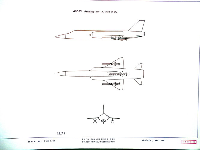
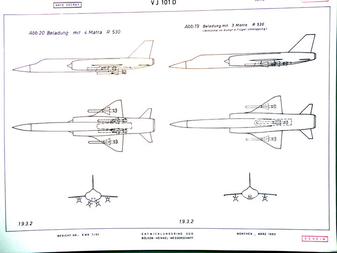
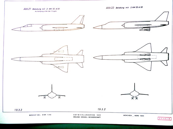
VJ 101 C - VARIANTS (illustration 21 to illustration 26)
Based on the VJ 101 C, parallel developments were carried out, which essentially included a change to the engine system and the wing geometry. While the aircraft design in Figure 21 differs from the preliminary investigations only by the additional lifting engine behind the wing, Investigation Figures 22 and 23 contain more advanced lifting engines. At the same time, the inlet for the lifting cruise engines and the wing structure were changed in accordance with the findings from the preliminary investigations into VJ 101 X 1. The draft in illustration 23 indicates a trainer variant based on the draft illustration 22.
Illustrations 24 and 25 show an aircraft variant with lifting engines. At the same time, the wing geometry was changed. While in the design in Figure 24 only the wing sweep was changed, in Figure 25 the span was also reduced and the wing geometry was changed from a swept wing to a delta wing. At the same time, the tail units underwent a change in their geometry.
Illustration 26 shows the attempt to replace the landing gear with air cushions under the fuselage and tilt supports on the engine nacelles. The technology of this aircraft is identical to that shown in Figure 22 except for the support system.
VJ 101 C 2 (illustration 27 and 28)
This project study dealt with the further development of the VJ 101 XI and X 2 experimental aircraft into a V/STOL fighter aircraft with a larger performance spectrum. This goal was to be achieved primarily through stronger and more modern engines, namely two GE 1 J 1 nacelle engines and two RB 162-34 hoist engines. The cell structure was essentially retained. The VJ 101 C 2 N version was intended to achieve even better performance using afterburner nacelle engines. The version equipped with afterburners differs from the normal version in that it has supersonic inlets and slightly longer engine nacelles.
In 1965, the two-seater versions C 22 and C 22 N were added in a further study. This proposed an alternative solution to the jointly developed German-American fighter aircraft. However, after further investigation, it was decided to use other configurations for performance reasons.
EWR VJ 101 - All variants part 4
16 PICTURES
VJ 101 XR (illustration 29)
This study investigated the possibility of equipping the VJ 101 X 1 aircraft with only 2 lifting cruise engines instead of the four RB-145. The following engines were planned: two RB 162-34 lifting engines in the fuselage and one SNECMA Mars M 45 A lifting cruise engine in each of the pivoting nacelles. The failure of a lifting cruise engine in the VTOL phase should be covered by additional powder rockets housed in the nacelles to prevent the aircraft from making excessive roll movements. This was intended to ensure the timely rescue of the pilot using the ejection seat. The airframe and all systems largely corresponded to those of the VJ 101
VJ 101 X 3 (illustration 30)
An investigation was carried out to derive a two-seat training aircraft from the VJ 101 X 2 (illustration 14) with relatively little effort. Since the operating radius would have become too small if the same engines were used, two RB 162-34 lifting engines should be used in the fuselage instead of the two RB-145 lifting engines. Calculated performance was similar to that of the VJ 101 X 2.
VJ 101 X 4 AND VJ 101 X 4 A (illustration 31 and 32)
The pre-project analysis of the VJ 101 In order to keep the effort as low as possible, only one lifting engine and only 1 lifting engine should be used in each gondola.
However, it turned out that the desired operating radius could not be achieved in this way and so a second lifting engine was provided in the fuselage for the VJ 101 X 4 A type. This measure made the radius of action approximately twice as large. Otherwise, the cell of the VJ 101 C was retained as far as possible; the equipment was provided in accordance with VAK 191 B.
TYPE 303 (illustration 33 and 34)
The Type 303 is primarily an enlargement of the basic type VJ 101 C. While the lifting cruise engines were obviously not changed, more powerful lifting engines were installed in order to prevent the excess thrust from increasing too much during cruise flight. In Type 303, illustration 33, an additional attempt was made to accommodate the lifting engines in a different arrangement in the fuselage. This is a two-seater variant.
TYPE 304 (illustration 35 and 36)
The Type 304 designs differ from the Type 303 in that they have a modified wing, the geometry of which was changed from a swept wing to a trapezoidal wing. The number of lifting engines was increased from 3 to 4, with the differences in arrangement being shown in Figures 35 and 36.
TYPE 305 (illustration 37)
The wing geometry corresponds to that of the Type 304. The number of lifting engines would be reduced from 4 to 3 as this is a smaller aircraft. The aircraft itself is designed as a single-seater.
TYPE 306 (illustration 38 and 39)
In the Type 306, fundamentally new arrangements of the lifting engines were used. The lifting cruise engines in the wing nacelles were reduced from a twin arrangement to a single arrangement. In the type 306 1 A (illustration 38), the lifting cruise engines are dual-circuit engines; in the study, illustration 39, it is a variant with single-circuit engines.
TYPE 307 (illustration 40 and 41)
The Type 307 designs, like those of the Type 306, are variants in which the number of lifting cruise engines in the nacelles was reduced from 2 to 1 each; Like the Type.306 1 A, these are dual-circuit engines. The difference in the hoist engine arrangements can be seen in the illustrations. The wing was modified from the Type 306 to a trapezoidal wing. The VTOL control around the roll axis should be carried out in addition to the thrust modulation of the lifting cruise engines by reaction control, which is supplied by the lifting engines.
TYPE 310 (illustration 42, 43 and 44)
As can be seen from illustrations 42 and 43, the previously pursued concept of the VJ 101 C development has been deviated from and the VJ 101 A development has been returned to. Of course, these designs differ in the details from the old studies. The wing geometry was changed, additional lifting engines were placed in the fuselage and the lifting cruise engines were moved from the wing tips to the fuselage.
As can be seen from Figure 44, an attempt is being made to dress the old concept in a more modern guise. The rear lifting cruise engines were housed in closed nacelle bodies that rest directly on the fuselage and the front lifting cruise engines were replaced by pivoting lifting engines. At the same time wing geometry and cockpit layout changed.
- Joined
- 15 February 2024
- Messages
- 500
- Reaction score
- 1,302
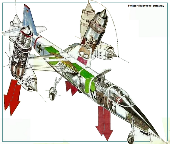
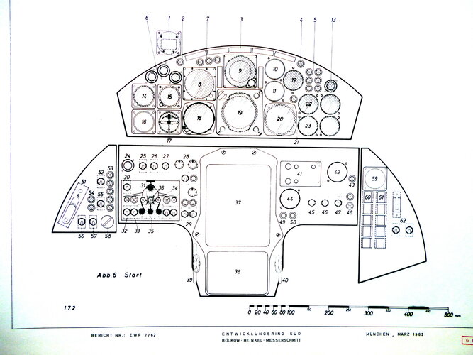
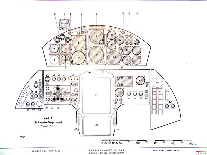
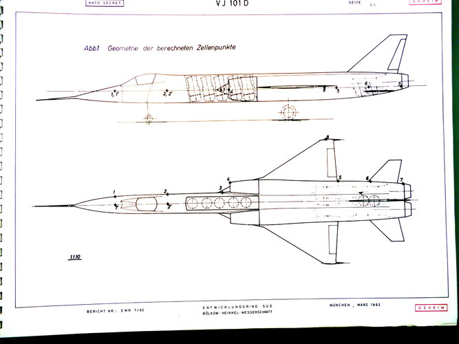
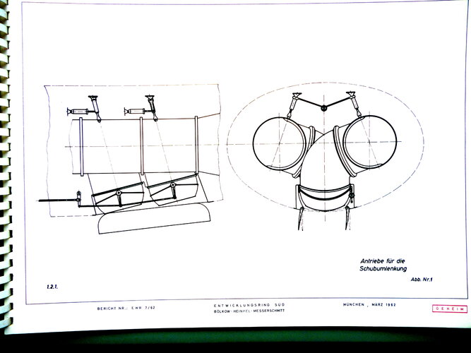
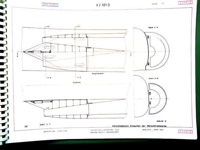
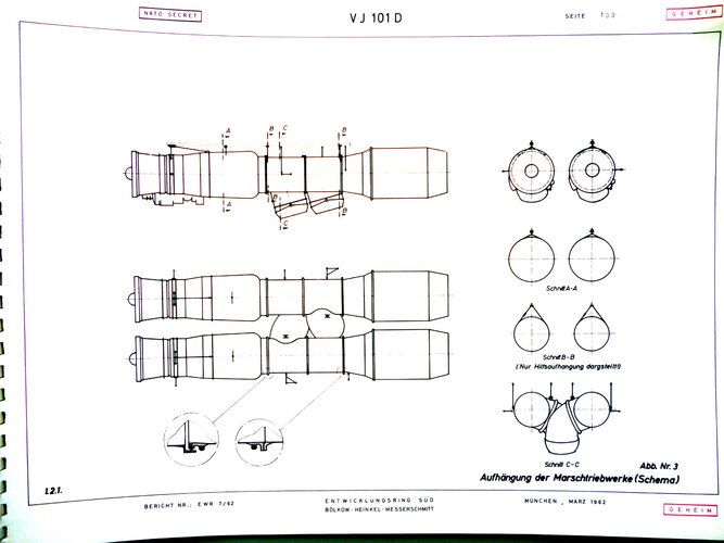
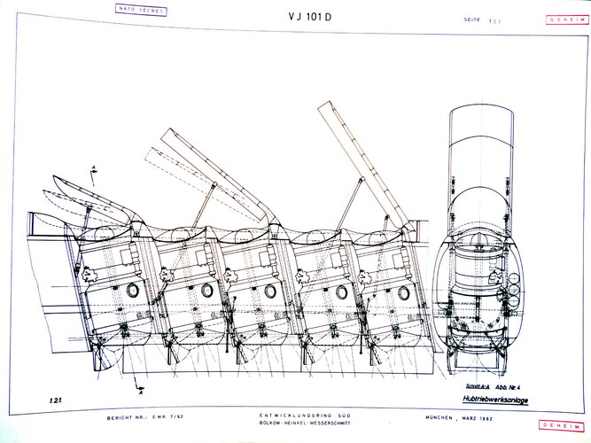
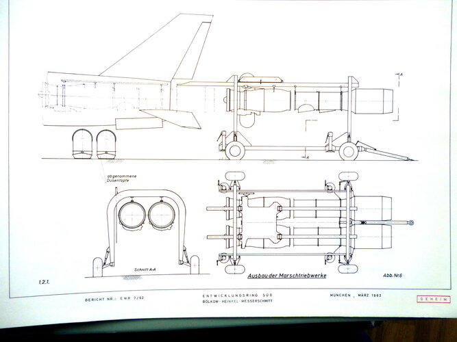
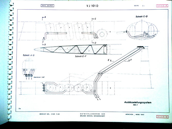
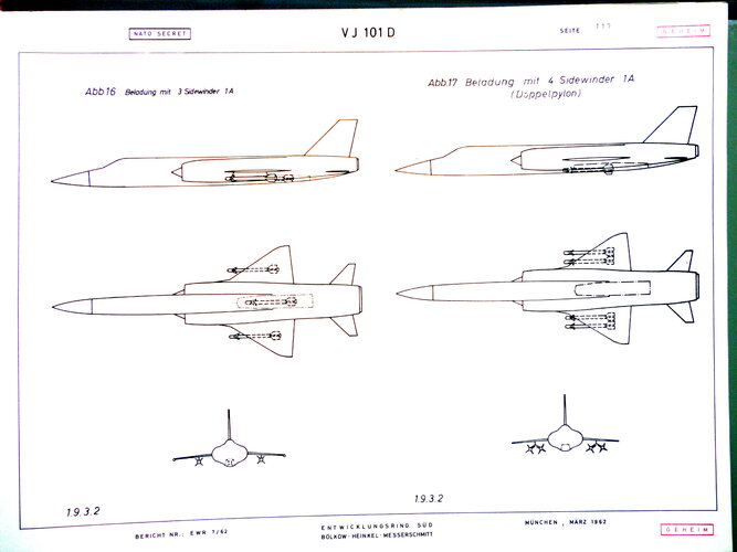
Few drawings of VJ-101D extracted from original notices.
Attachments
-
 VJ101 (PhR17).JPG943.7 KB · Views: 83
 -
 VJ101 (PhR16).JPG1.1 MB · Views: 75
 -
 VJ101 (PhR15).JPG597.3 KB · Views: 81
 -
 VJ101 (PhR13).JPG622.3 KB · Views: 71
 -
 VJ101 (PhR12).JPG673.4 KB · Views: 62
 -
 VJ101 (PhR11).JPG622.1 KB · Views: 65
 -
 VJ101 (PhR10).JPG1.1 MB · Views: 70
 -
 VJ101 (PhR9).JPG626.1 KB · Views: 69
 -
 VJ101 (PhR8).JPG728.1 KB · Views: 71
 -
 VJ101 (PhR1).JPG704.9 KB · Views: 70
 -
 VJ101 (PhR2).JPG986.9 KB · Views: 66
 -
 VJ101 (PhR3).JPG551.5 KB · Views: 69
 -
 VJ101 (PhR4).JPG374.5 KB · Views: 64
 -
 VJ101 (PhR5).JPG554.8 KB · Views: 65
 -
 VJ101 (PhR6).JPG529.1 KB · Views: 65
 -
 VJ101 (PhR7).JPG768.9 KB · Views: 83
- Joined
- 15 February 2024
- Messages
- 500
- Reaction score
- 1,302
- Joined
- 27 December 2005
- Messages
- 17,748
- Reaction score
- 26,408
Ooooooh!
Nice brochure you have there")
Nice brochure you have there
Similar threads
-

-
 What if VJ-101C or its modified variants replaced F-4 and being adopted by Luftwaffe in ATL?
- Started by StraGen410
- Replies: 11
-
 German VTOL Business Jet
- Started by Michel Van
- Replies: 7
-
-
 Otto Funk, Peter Funk, & Bücker und Funk Designations
- Started by Apophenia
- Replies: 2