jmkorhonen

Diletantte
Joined
28 January 2013
Messages
11
Reaction score
5
Website
jmkorhonen.net
...so as not to hijack the British thread!

Let's start with a subject to which I hope to be able to make a meager contribution to: design constraints and philosophy behind design decisions.

Hermione Giffard's PhD thesis and hopefully soon-to-be book "The Development and Production of Turbojet Aero-Engines in Britain, Germany and the United States, 1936-1945" (2011) argues that German and British gas turbine development was (at least in part) guided by quite different design philosophies and quality goals. Although the following is a crude generalization, the difference seems to be that the British were developing jet engines to standards expected of from piston aero engines (e.g. reliability, materials usage, MBTO etc.), while the Germans - specifically in the last half of the war - were doing "ersatz piston engines."

Giffard makes (IMHO) quite a convincing case that many of the German design decisions, with the possible exception of the adoption of axial flow scheme (which, however, was largely "locked in" by earlier design considerations), may be more fruitfully interpreted in the light of ease of production and conservation of raw materials. Turbojets fit nicely into the "armaments miracle" drive that sought to compensate the crushing manufacturing superiority of the Allies by rationalization, mass production, and focus on quantity even at the expense of quality. The man-hours required for a turbojet, for example, were a fraction of the man-hours required for a comparable piston engine, and raw material expenditure was far lower (more on that below). Lower quality was also acceptable because the expected lifetime of the engines was not a limiting factor - the expected lifetime of airframe into which the engines were mounted was, at this point in the war (1944) usually shorter than the expected lifetime of the engine.

When seen in this light, several interesting design decisions become, in my opinion, more understandable. For example, one thing that had puzzled me was the frequent claim that nickel shortages had "caused" the development of the hollow turbine blades. Several scholars in the field of technology & innovation studies (e.g. Gibbert & Scranton 2009) have claimed that Ni shortage "induced" this "radical innovation" that put the German jet engine designers several years ahead of the Allies and caused them to "invent" a technology that is in use even now.

However, this version of the events seems a bit problematic when one considers the actual nickel usage and Germany's nickel situation. According to figures for Ni usage per engine in Kay's "German Jet Engine and Gas Turbine Development 1930-1945" (2002), the entire production run of Jumo 004 engines, for example (some 6010 engines) used approximately 40 metric tons of nickel. This is not an insignificant amount, but compared to 1944 Ni supplies (10900 tons), consumption (9500 tons), or stocks (7900 tons) (U.S. Strategic Bombing Survey), the needs amount to little more than rounding error.

Even if the wildly optimistic turbojet production plans, calling for ca. 39 000 BMW 003 and 44 000 Jumo 004 engines to be built by January 1946 had materialized, the nickel use would have been only some 250 tons. And even if the hollow blade designs - which, at best, saved some two thirds of nickel per engine compared to solid Tinidur blades - had not succeeded, the nickel consumption would have been only about 820 tons.

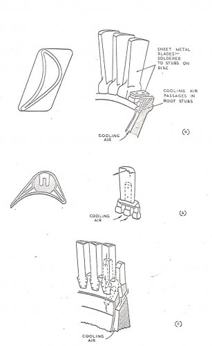
So, to me it seems that the relationship between nickel shortage and hollow blades is not as straightforward as it may seem. As Giffard argues, another (and perhaps the key) factor in favor of hollow blades was the ease of manufacture: hollow blades were deep drawn or folded and welded from sheet metal stock, and both operations were much more conductive to mass production using unskilled (slave) labor. Nickel savings were a plus.

I'm not claiming that the designers had all the nickel they wanted: there is no doubt that the designers "felt" the nickel shortage in the form of specifications and demands issued. For example, according to Kay (2002:107), in 1944, a specification for BMW 003 A-1 production series engine requested that engine had to be produced for about 500 man-hours per unit, and that it should use no more than about 0.6 kg Ni per engine. (The requests were not quite achieved, but it was reasonably close.) But, in my mind, the interesting question is this: how the specifications came to be?

Specifications don't crop up in a vacuum, of course. Before the official request for 0.6 kg of nickel per engine could be made, either a) someone must have had a pretty good idea about what's the minimum amount of Ni an operational engine would need, or b) someone needed to be delusional. Not to say that the b) couldn't be a factor, but the evidence (the target was almost reached) points that the specification set a pretty reasonable if ambitious goal. The most likely explanation for that is there was at least some confidence that engines could be built with little Ni. And that confidence largely came from a history of experimentation with air-cooled turbine blades.

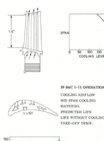
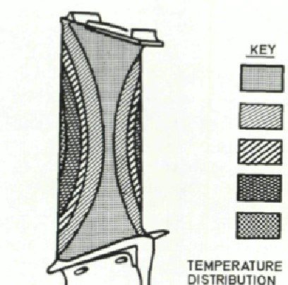
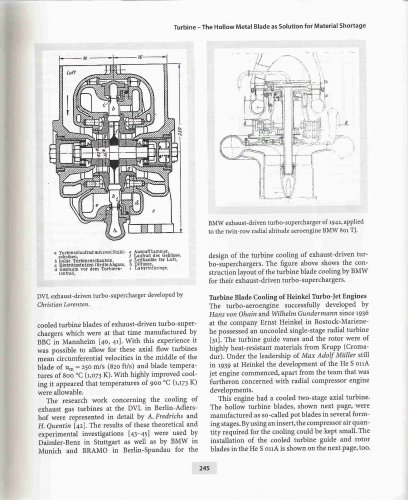
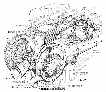
The German industry had been aware that in any possible war, nickel would be one of the key metals in short supply. Consequently, even before the war, efforts had been made to develop alternatives and R&D on nickel-heavy alloys was curtailed: e.g. Krupp works did not introduce an improved Tinidur alloy with 60% instead of 30% Ni because of the anticipated shortage, even though the high temperature advantages were known (Meher-Homji 1997). One of the areas in which this awareness manifested itself was in superchargers, which were the first applications of hollow turbine blades: a BMW turbo-supercharger ran successfully at 900°C in 1938, using internally air-cooled blades.

I argue that it was this and other successful hollow-blade developments that influenced the perceived nickel shortage by at least as much as the actual supply situation. Because the powers that be knew that turbines without solid nickel-alloy blades could be manufactured, and that they were easier to manufacture than milled turbine blades, the specifications could confidently call for very low Ni content per engine, and the armaments ministry could get by lower Ni allocations to jet engine manufacturers. True, the anticipated nickel shortage was one reason the engineers started to design workarounds in the first place, but if these efforts had failed, I don't see any reason why the Germans would have been unable to continue using solid blades (as used in Jumo 004 B-1, which was the only turbojet to power planes that actually reached combat) or even introduce alloys similar to Nimonic 80 for the jet engine program - although that would probably have been excessive, given the likely lifetime of the airframes. After all, even with Nimonic, the nickel use per jet engine would have been less than what was needed for comparable piston engines! (My approximation based on early 1942 data on aero-engine industry nickel consumption is, on average, 50 kg per piston engine. I'm not certain what that includes - it may include tools and dies and all the other stuff required in the supply chain. Any info would be much appreciated.)

A bit longer version of this case study may (hopefully) become a part of my PhD thesis. My thesis draws from the history of technology and, at this point, seems to argue that the role of constraints in design and engineering might be understood a bit incompletely in the current science & technology studies literature: instead and in addition of "necessity being the mother of invention," technical possibility is one of the most influential parents of necessity, as defined by specifications and requirements. Any criticism would be much appreciated, much easier to change thinking at this stage when nothing's in print yet :).

References:
Anonymous. 1938. Aeronautical Research: Dr. Seewald Describes the Work of the DVL. The Aircraft Engineer (Supplement to Flight), 16(11): 71–74.
Gibbert, M., & Scranton, P. 2009. Constraints as sources of radical innovation? Insights from jet propulsion development. Management & Organizational History, 4(4): 1–15.
Giffard, H. S. 2011. The Development and Production of Turbojet Aero-Engines in Britain, Germany and the United States, 1936-1945. Imperial College, University of London.
Kay, A. L. 2002. German Jet Engine and Gas Turbine Development 1930-1945. Ramsbury: The Crowood Press.
Meher-Homji, C. B. 1997. The Development of the Junkers Jumo 004B—The World’s First Production Turbojet. Journal of Engineering for Gas Turbines and Power, 119(4): 783. http://gasturbinespower.asmedigitalcollection.asme.org/article.aspx?articleid=1420400, March 30, 2013.

PS. an astute reader may note that I left out discussion of chromium from the above. I do not consider this to have been a critical resource for jet engine development, as (partial) switch to Cromadur blade material even increased Cr use per engine in order to conserve nickel.
 
The first German jet engine to run and to fly was a centrifugal (Heinkel). Giffard's book has cutoff dates which mean that the context of what she writes is skewed. Henkel of course was not in favour with the regime and so was cut out of some developments... such as Me109 type etc....
The reason for Germany's adoption of the axial was due to their superior understanding of axial flow compressors and their early understanding of the importance of aircraft frontal area on performance... combining the two represented a cogent argument for axial-flow turbine development... in Britain there was a hiatus, as I have written in the other stream, when Griffith moved from RAE in 1928... it was 7 years I think before we got going again at RAE. Whittle realised that with our work on centrifugal superchargers that a radical new engine would be easier to achieve using the bigger diameter compressor.

One should approach H. Giffard's work with caution.. having read it and compared with other stuff I think she challenges some conventional thinking but ultimately, I believe, fails by drawing overall conclusions from only part of the story.
It is also worth remembering that Germany was bankrupt in the early thirties and so could not trade in metals, oil etc that it needed for reamament.
when Hitler came to power there was little foreign currency reserves and zero credit so they had to be more ingenious than Britain who had access to the Empire's resources and foreign exchange for the rest. David Edgerton's book Britain's War Machine: Weapons, Resources and Experts in the Second World War makes the case taht our ability to gear up to war production was far in excess of Germany's and so as long as we could resist the first onslaught we would most likely win... but it was still a close run thing!
 
It is very interesting how in the twenties Britain decided to develop the centrifugal as a private venture whilst government researchers favoured the axial... this was similar to Germany with one exception. The German govermenment went for the axial and this is waht industry fell in with but it was not till many years later that Heinkel decided to back an engineer/inventor who was trying to develop a centrifugal... which flew before their axials. When my Pc is restored I will discuss what I have found out about the 1920-30's pre war period and why we were more successful in the short term.
 
Nickel is used throughout a Merlin piston engine...Hiduminium aluminium alloys have 1-2% Ni, Nickel steel about 3%; heat exchangers have copper-nickel etc... so 50kg per engine feels about right for an engine of dry weight of 744 kg. All the evidence of German engineers points to the need to use low creep strength alloys as the reason to develop blade cooling technology which is not easy. As the jet engines were being developed well before the Germans thought of using cooled blades it is likely that economy of materiaals drove the material choice, not the type of labour... after all the war wasn't going to last long, was it?
Of the eight key German jet developments only 3 were started during the war, which also points to the lack of access to Nickel etc as a driver of the turbine innovations.
 
All the indecision in the German institutions led to prolonging the gestation of the aircraft programmes involving jets. The Me 262 suffered many a redesign at the paper stage before becoming a prototype. Did n't mean it didn't improve the breed but as Hives often said in a Merlin context "the best can be an enemy of the good".
Here is a page from Torquemeter to illustrate the point.
 

Attachments

  • 002.jpg
    002.jpg
    503 KB · Views: 976
tartle said:
Nickel is used throughout a Merlin piston engine...Hiduminium aluminium alloys have 1-2% Ni, Nickel steel about 3%; heat exchangers have copper-nickel etc... so 50kg per engine feels about right for an engine of dry weight of 744 kg. All the evidence of German engineers points to the need to use low creep strength alloys as the reason to develop blade cooling technology which is not easy. As the jet engines were being developed well before the Germans thought of using cooled blades it is likely that economy of materiaals drove the material choice, not the type of labour... after all the war wasn't going to last long, was it?
Of the eight key German jet developments only 3 were started during the war, which also points to the lack of access to Nickel etc as a driver of the turbine innovations.

Thanks again - this is extremely useful, nay, invaluable for me. And sorry for a delay in answering, had a swarm of deadlines to combat.

I concur with your assessment, but I'd still argue that the nickel allocation in Germany and hence the perception by aero-engine designers of nickel being scarce was heavily influenced by the Armaments Ministry etc. having knowledge that low-Ni alternatives (e.g. internally cooled turbochargers) were feasible. If there hadn't been existing R&D - and demonstrated results from said R&D - I believe the Armaments Ministry in charge of nickel allocations would have simply allocated enough nickel to jet engine program to continue building solid-blade engines, perhaps even from Krupp's prototype Nimonic-like alloy. The jet engine program was, after all, a bit player in the overall German nickel consumption.
 
If you read any authoritative work on German munitions production during WW2, including academeic work by Germany itself you will see the effect of the League of Nations embargo in early thirties on such things as Nickel imports. Germany was short of foreign exchange in the thirties so still could not buy enough for its needs. Also being supremely confident of its ability to quickly conquer Europe, the regime saw no need to try harder to get supplies. The Allied blockade of Germany made sure they were not only short of the 'right' metals but aircraft fuel as well. So I think the efforts of the Germans on air cooling etc were a metals issue not a desire to raise the overall efficiency of the gas turbine cycle. It also limited the scope for piston engine development. There was no way the Germans could have produced Nickel chromium alloys to meet their needs the way we could.... so perception was also reality... where were the metals to come from?
 
The original intention of sponsoring Hermione Giffard's researches was to tease out the stories of von Ohain's and Whittle's efforts and establish a relative priority for their achievements. Her thesis neatly sidesteps this by putting a date cutoff that effectively eliminates both of them from the story!
So let's see if we can do any better!
I have written on Whittle ... so here goes for Hans Joachim Pabst von Ohain. von Ohain flew in a Junkers 52..it horrified him and he exclaimed
"The propellers made a horrendous noise. The airplane rattled because it had piston engines. You couldn't even talk to your neighbour. It was not as romantic as I thought it would be. ... I thought flying should be elegant." This sparked his search for a smoother prime mover!
There are several good accounts of the early gas turbine work of von Ohain... this one has a good pedigree as its author, Col. Walter J. Boyne USAF (Ret) was director of the US Airforce Museum and is known for his excellent research. (It also touches on material shortages)
Cyrus B Meher-Homji also wrote what might be regarded as the definitive account of his work for ASME Jnl for Gas Turbines and Power,
I have taken his timeline and reproduced it below.
For continuity in the story
However all these stories do not mention a Dipl. Ing. Wilhelm Gundermann, who was a key member of the Heinkel team responsible for the Design and Development of the original centrifugal designs. In the early 1970s the MTU people were translating the German-language account of that person into english. these are some of my tc notes:
von Ohain had no formal training in engineering so when he joined Heinkel WG was assigned to his team. von Ohain was allowed the pick of the workshop personnel for his team and soon had six to eight fitters and mechanics in his workshop. WG had studied aeronautical engineering at the Technical University of Berlin and turbo machinery engineering under Prof Hermann Fottinger so was an excellent addition to the team... he soon had between six and eight designers, draughtsmen and stress analysts working for him... most recruited from outside Heinkel. Max Hahn was still with the team having left his garage employment to accompany von Ohain.
WG was aware of non-compressible fluid mechanics equations and soon delved into technical handbooks to learn about compressible gases... however there were no works to cover centripetal turbines so they derived their calculations to drive the turbine characteristics. The stressing techniques for steam turbines were adapted for their purposes. The axial passage width for the compressor and turbine were determined by accounting for the temperature rise and then the volume increase due to combustion. The vane angles in the compressor diffuser and turbine stator were calculated from the latest theory and then three sets of each were made; one to the calculated vane angles and one each a small increment above and below that value. This would enable the correct settings to be determined by comparative testing. Although the DVLR had developed special high grade steels for exhaust gas turbines the turbine blades and discs were manufactured from a high temperature exhaust valve steel which gave a better balance of properties. Hahn of course played a major role in the manufacturability aspects of the design and was also a key figure in laying out the design of the combustion chamber (CC); he had been a major contributor to this area on the original Gottingen experimental rig. As we saw on the Whittle saga the CC is notoriously difficult to get right. It took the team at Heinkel 18 months to get the liquid-fuelled version CC to work well - the final design consisted of 16 partial chambers that had a vapouriser initially heated by hydrogen on startup until the petrol flame could do the job. The vapouriser was manufactured from 36% nickel alloy welded together.
.....tbc below
 

Attachments

  • Timeline4early german gas turbines.jpg
    Timeline4early german gas turbines.jpg
    147.1 KB · Views: 728
The shortage or not of materials... the papers at this conference and the resources they represent may be worth following up...
 
I thought it is worthwhile just summarising the work before Heinkel...
The first jet engine von Ohain created (using money he received from selling his patent to do with putting sound on film- bought by Siemens) was what today we call a 'proof of concept' demonstrator. This was not self-sustaining but excited his prof. enough for him to contact his colleague Heinkel and suggest he took a look at him. The first three pics show the demonstrator constructed by the garage 'mechanic' Max Hahn; the rotating assembly with centripetal turbine; Max Hahn next to the demonstrator.
As my strapline quotes "... prototypes are a way of letting you think out loud. You want the right people to think aloud with you.” Prof. Robert Pohl advised Von Ohain to contact Ernst Heinkel as they both realised full development would need a lot of finance. Heinkel and his two chief engineers, the Gunter Brothers were very focused on 'the need for speed.
We have discussed above how Heinkel set up a project office to pursue the gas turbine and the involvement of Wilhelm Gundermann... so picking up the theme:
The next pic shows the first prototype, HeS1- we discussed above.
This used hydrogen as the fuel, in order to get prototype running quickly; the knew that liquid-fuelled combustion chamber was a development challenge needing a great deal of time to perfect.
On March 17 1937, the He S1 turbojet engine with hydrogen fuel was tested and produced a thrust of 250 pounds at 10,000 rpm. Von Ohain reported: "The apparatus fully met expectations. It reached the anticipated performance, it handled well in acceleration and deceleration, probably because of the relatively small moment of inertia of the compressor and turbine rotor and the great stability of the hydrogen combustion over the wide operational range."nkel pressed for an accelerated flight engine program. Von Ohain's team began development on the He S3 engine, having first looked at modifying the HeS1 to accommodate a larger combustion chamber. The need for more power drove several iterations and eventually Gundermann drew out the HeS3b scheme which became the flight engine.
One of the iterations was under a He 118:

The He 118 V2(1294) made it's mark in history however by being the first aircraft to fly, even if briefly, with a HeS3a turbojet engine. This was in the summer of 1938, when testing of the new engine moved from the testbed to finding out how it would perform under flying conditions. The engine was mounted beneath the fuselageon the bomb mounting between the wings of the He 118. It had a high ground clearance which allowed for the safe fitting and maintenance of the engine. Test flights would start at around 4am and end at 6am this was to keep the development secret, the He 118 would take off under the power of it's piston engine, later igniting the He S 3a, which would result in a loud noise and a blue flame from the jet engine and a notable turn of speed from the He 118.
tbc
 

Attachments

  • He118V2-HeS3.jpg
    He118V2-HeS3.jpg
    22.6 KB · Views: 122
  • He S 3b-GA-gundermann.jpg
    He S 3b-GA-gundermann.jpg
    66.4 KB · Views: 102
  • von ohain-first demonstrator gas turbine in garage workshop.jpg
    von ohain-first demonstrator gas turbine in garage workshop.jpg
    369.8 KB · Views: 554
  • von ohain-first demonstrator gas turbine rotor assy.jpg
    von ohain-first demonstrator gas turbine rotor assy.jpg
    368 KB · Views: 574
  • von ohain-first demonstrator gas turbine.jpg
    von ohain-first demonstrator gas turbine.jpg
    481.1 KB · Views: 595
The next thing Gundermann concentrated on was 'how do you install the jet in a fighter?'
His first idea was to bury it in the wing- a twin installation- like the Comet airliner. the engine would be put in a structural tube between the 2 wing spars to restore torsional stiffness. this was rejected by Heinkel because he did not like it and it infringed Messerschmitt patents.
Heinkel also said he wanted a single engine installation so it was to a fuselage layout that Gundermann next turned his attention. He started with a He 100 fuselage design and schemed out how to build in a HeS3b. Whilst the layout was being schemed Gundermann had a test bed installation tested... this had a short intake and exhaust typical of an underwing installation; this gave 992 lbt. With a long intake this dropped to 834 lbt showing the He 178 ducting gave a 15% thrust penalty. Once Gundermann had schemed the intake the He178 Heinkel's project office got on with detailed design. this was led by company technical director, Prof. D Hertel, the chief designer was Director Schwarzler, Chief Project Engineers Seigfried and Walter Gunter; a hangar was allocated to two engineers, Kunzel and Raue, who built the two airframes.
Gundermann, aware of the need to provide as much thrust for high-speed had schemed several ideas for a variable nozzle which would allow a larger outlet area on take-off and smaller at high speeds, but it was decided not to incorporate this on the first aircraft as it was not anticipated that they would fly at speeds fast enough to justify the risk and complexity, given all the other imponderables! Werner von Braun's test pilot was entrusted to fly the aircraft and came from Peenemunde to Marienehe to conduct the flights. Capt. Erich Warsitz conducted taxying trials on 24 August 1939 and had a first hop to test the undercarriage (that had been fixed and faired over for the first flight) and controls followed by the first flight on Sunday 27 August. Ernst Udet (Director of General Equipment) who had visited often to observe progress on the He178 and had seen an early HeS jet running was informed and came down a few days later to see Waritz in the air. This precipitated a wider and more urgent gas turbine programme. The photograph below of Waritz testing the He 178 without the cockpit canopy is a frame taken from the of the initial flight; note the taxying part at first then it fades into the first takeoff. Note that the first part has no canopy and was filmed on the 24 August 1939; the take-off has a canopy and is a record from 27 Aug.

...tbc
 

Attachments

  • He178 with HeS3.jpg
    He178 with HeS3.jpg
    152.9 KB · Views: 84
  • HE 178 24aug39.jpg
    HE 178 24aug39.jpg
    55.6 KB · Views: 78
  • He 178-27aug1939.jpg
    He 178-27aug1939.jpg
    1 MB · Views: 81
Thanks... corrected... I've seen typos become fact that have mislead my researches several times!!
 
Thanks again, Tartle. Wonderful information.

I've been tracing the development of hollow blade design to its roots, so to speak, and the earliest reference I could find was to internally air-cooled turbochargers built and tested by Lorenzen in about 1929. Do you by any chance know anything about these, and how about British pre-war/wartime turbocharger design - did they use air-cooled turbines?
 
Turbochargers go back to Jimmy Ellor at the RAE Farnboro' ... they were solid then and so that continued into the late twenties.... developments in metallurgy and the ample supply of strategic materials such as nickel and chrome meant that high temperature challenges could be met by the use of new materials. Inter-war Germany had no money to buy in strategic materials and even after invading places such as Norway did not exploit the potential source of nickel; so the need to air cool components was a high priority to make up for inferior metals.... and also a sacrifice of service life.
Therefore the UK did not pursue internally cooled blading on turbochargers; they had abandoned development of them anyway in the late twenties; when they returned to them at Bristol in the early years of WW2 they used American GE turbos; RR when they looked at turbos for the Crecy scaled the solid turbine blades from the WR1; Nimonics were very useful materials and it was only post war that the UK began to address the issues of internally air cooled blading; conclusion as with turbojets is that we did not need to aircool so why take on all the issues when there are enough already- the Metrovick F2/4 was as if not more reliable than the equivalent German engine but was not put into production as the RR and DH centrifugals were far more reliable and we had a war of attrition to fight!
tbc
 
jmkorhonen,
to misquote 'out of the tea chest'! I am slowly wading through the intelligence reports from Germany at end of WW2 and will eventually summarise them.
The first figure shows how the Heat transfer coefficient varies around a blade section; it is high at leading edge as the laminar boundary layer is very thin, the value will decrease as the boundary layer builds up in thickness and then leaps when there is a transition point to turbulent conditions when the hot gas can come into contact with the surface. The degree of reaction can affect where the transition takes place and therefore what the average HTC will be for the section (used in Z-factor comparison below). A high reaction blade will tend to have a delayed transition point so will have a lower mean HTC.
The heat transfer coefficients (= heat quantity transferred per second per unit surface area per degree temperature difference between gas and surface) is best used as a non-dimensional quantity known as Nusselt Number (nu= ((heat transfer coefficient*blade chord)/ thermal conductivity of gas stream)
In the meantime D G Ainley of NGTE presented a paper in 1956 on 'The High Temperature Turbo-jet Engine'. He derived a Z-factor which is a figure of merit to rank different cooling passage configurations within a given turbine blade section and then commented on German designs using this factor.
Ainley in an unpublished note derived the Z-factor:
((S/C)**1.2)/(A/C**2) where S= blade pitch; C= blade chord and A is cooling passage cross sectional area.
Typical good design of blade e.g. Avon or Conway gives a Z of up to 200 for extruded Nimonic designs.
The Germans adopted turbine cooling early due to lack of high-temperature resistant alloys.
Up to 1945 the Germans confined themselves to plain hollow blades with simple inserts. Such blades give low Z-factors resulting in relatively poor cooling. The Jumo is very low on 'Z' hence the difficulty to raise blade life above 50 hours even on derated engines.The most promising blade was possibly that developed for turbocharger applications by the DVL. This had a thin blade shell spot-welded to a strong internal(structural) pillar of simple shape. Cooling air was forced through the spaces between the pillar and blade shell and up a channel in the pillar itself. Thus the main stress carrying member was relatively well cooled. The leading and trailing edges were relatively poorly cooled but the main danger was buckling and oxidation of the shell rather than catastrophic failure. The Z-factor for this blade was 50-60. See third figure for relative designs.
The 4th picture shows the relationship between Z-factor and blade average metal temperature for a cooling flow of 1.5% of main engine flow a pitch chord ratio of 0.75, outlet gas angle of 60 deg.
Note that the outlet angle is a measure of the reaction of the stage and has been found to be a good correlator.
The 5th picture shows a plot of relative blade temperature (actual to uncooled metal temp) vs a parameter that is the product of cooling flow ratio phi and gas outlet angle alpha relative to engine axis and pitch/chord ratio showing how variation of Z affects metal temperature.
 

Attachments

  • turbine blade-influence of Z factor on cooling a nozzle row-ainley-1956.jpg
    turbine blade-influence of Z factor on cooling a nozzle row-ainley-1956.jpg
    46 KB · Views: 250
  • turbine blade-a-typical 004-b and c-DVL turbocharger design-ainley-1956.jpg
    turbine blade-a-typical 004-b and c-DVL turbocharger design-ainley-1956.jpg
    78 KB · Views: 260
  • turbine blade-requirements for efficient internal air cooling-ainley-1956.jpg
    turbine blade-requirements for efficient internal air cooling-ainley-1956.jpg
    87.4 KB · Views: 259
  • turbine blade-variation of local HTC around typical sectn-ainley-1956.jpg
    turbine blade-variation of local HTC around typical sectn-ainley-1956.jpg
    51.8 KB · Views: 260
Excellent - was able to follow up a bit on Jimmy Ellor and that enabled me to fill up some gaps in my timeline. Didn't really realize before that early jet engines shared so many conceptual similarities with turbochargers! Thanks. (By the way, this thread in another forum was of great help as well ;) http://www.theaerodrome.com/forum/aircraft/50719-increasing-charge-5.html)

I don't have the Ainley paper and my university doesn't seem to have it in their collection, but the following 1967 paper by G.A. Hall references his work and discusses the z factor. Thanks for the formula, my copy is of a bit poor quality and I misread the formula to be Z = S^1.2 / C^1.2 minus A / C^2, which stymied me a bit! :eek:

Some z factors mentioned as examples in the paper:

Conway: 31
Tyne: 33
Spey: 101

So it seems the DVL blade was actually pretty good in terms of cooling?

I'll do the z values for Jumo 004B-4 and BMW 003 later when I have the drawings with me, but if you happen to have them on hand from, say, Ainley paper, I wouldn't mind :).

Halls, G. A. (1967). Air Cooling of Turbine Blades and Vanes. Aircraft Engineering, 39(8), 4–14.
 
jmkorhonen wrote:
I've been tracing the development of hollow blade design to its roots, so to speak, and the earliest reference I could find was to internally air-cooled turbochargers built and tested by Lorenzen in about 1929


Can you please develop a bit on Lorenzen`s work? I believe he started during WW1.
 
jmkorhonen... we are in fact in alignment on the Z factor... G A Halls spoke of the RR Spey and confirmed that the Z factor of the hp extruded blade is 101.. the lines of Z on pic below are his department's theoretical calculations for variations in passage number and area.
the Z-factor technique only works for a single pass of cooling air, i.e. in at bottom out at top.
Quoting Halls:
"Tyne, Conway and Avon cooled blades are very similar In that they all feature
three spanwise holes. This cooling configuration was conceived In the early
1950's and blades were being made in full scale production by 1956. The simplicity
of the system is Indicative of the manufacturing techniques which existed
at that time.
The Tyne blade is shown on figure 5-13 together with some of the salient statistics.
This Is the smallest forged blade produced by Rolls-Royce. Cooling
air enters at the blade root, passes up the trailing edge hole, down the centre
hole and up the leading edge hole, to exhaust at the blade tip.
The cooling airflow, expressed as a percentage of the main turbine flow is
just under 1% and this cools the midspan section of the blade by an average of
40°C. The modest amount of cooling Increases the blade life from 2000 hours
uncooled to a predicted 7000 hours. The achieved life to date Is 6500 hours.
The Tyne engine has accumulated 4.1 million hours in engine operation (to
May 1967). The z factor for the Tyne aerofoil is 33. 0.
Conway blade—This Is also a three hole blade and the Avon Is virtually Identical
to It and Is shown, with the relevant statistics, In figure 5-14. In this design
cooling air flows from one side of the blade root up both leading and trailing
edge passages, turns over at the blade tip to flow down the centre passage and
then exhausts at the blade root on the opposite side of the blade. The amount
of cooling air used Is 1.47% of the main turbine flow and this cools the midspan
average temperature by 120°C. If this blade were uncooled It would have a life
of 75 hours but with cooling a life of 15 000 hours is predicted and 13 000 hours
has been achieved. The Conway engine has accumulated 6. 2 million hours of
service operation (to May 1967). The z factor of this blade is 31.0.
The low z value of both Tyne and Conway blade implies that if the air passed
straight through the blade the cooling would be very inefficient. It is in an
effort to conquer this shortcoming that more than one pass of the cooling air
was used.
Spey blade—This type of blade, shown on figure 5-15, has elliptically shaped
cooling holes formed by a unique manufacturing method. Cooling air enters
the blade from both sides of the root and exhausts from the tip of the blade,
thus giving the single pass cooling system of the type analysed by Ainley.
The cooling airflow used Is 2 per cent of the main turbine flow and this reduces
the midspan average blade temperature by 220°C.
If uncooled, this blade would last for only 12 minutes. The predicted service
creep life of this blade Is In excess of 10 000 hours. The aircraft using Spey
engines have only been in service since April 1964, so the total number of
running hours so far accumulated Is relatively small (0.8 million hours)."

All this leads to Halls' conclusion about the Z-factor technique:
"Limitations of Simplified Design Philosophy
There are three major shortcomings in the simplified one dimensional heat
transfer approach to cooled blade design as documented by Alnley.
1. It can only be used for a 'single pass' system. It has already been noted
that the need for a high value of 'z' can In some measure be defeated by using
a multipass blade like the Tyne or Conway. Though in fairness it should be
said that the one-dlmenslonal heat transfer approach can be adapted to cater
for the multipass system. Cooled nozzle guide vanes In service engines today
have cooling systems differing radically from a single pass system. Cooled
blades at present In the experimental stage differ just as drastically. For these
systems the one-dlmenslonal heat transfer method has to be discarded. Instead
testing and cut and try methods often replace theory.
2. The second shortcoming of the one-dlmenslonal heat transfer method Is
this. In carrying out the design procedure one can arrive at a single pass configuration
that gives adequate cooling. In fact one might arrive at any number
of configurations all of which could give adequate cooling. Unfortunately, because
operating conditions and geometrical sizes may be different, one Is not
able to compare the new design with one which Is working satisfactorily on
another engine.
3. The third shortcoming arises from the assumption of uniform chordwise
temperature, and from the two underlying presumptions (a) that failure occurs
when the chordwise average temperature reaches a critical value and (b) that
all cooling passages are equally effective in cooling the blade. The surface
temperature distribution of the Conway blade, measured with temperature sensitive
paint, is shown on figure 5-19. It can be seen that chordwise temperature
departs a long way from uniformity."
But this does not invalidate the approach for comparing the early German designs.
By the way I have just checked my pre print and the final paper is in AGARDograph 120 here.
 

Attachments

  • Turbines-Spey hp z factor vs cooling airflow-GA halls-1967.jpg
    Turbines-Spey hp z factor vs cooling airflow-GA halls-1967.jpg
    14.3 KB · Views: 65
  • Turbines-Tyne and Conway-GA halls-1967.jpg
    Turbines-Tyne and Conway-GA halls-1967.jpg
    35.4 KB · Views: 70
  • Turbines-Spey single pass-GA halls-1967.jpg
    Turbines-Spey single pass-GA halls-1967.jpg
    18.6 KB · Views: 70
  • Turbines-Conway blade surface data-GA halls-1967.jpg
    Turbines-Conway blade surface data-GA halls-1967.jpg
    39.6 KB · Views: 95
Lorenzen's work as reported in ARIG, p.245
 

Attachments

  • ARIG-p245.jpg
    ARIG-p245.jpg
    251.3 KB · Views: 128
Wurger said:
jmkorhonen wrote:
I've been tracing the development of hollow blade design to its roots, so to speak, and the earliest reference I could find was to internally air-cooled turbochargers built and tested by Lorenzen in about 1929


Can you please develop a bit on Lorenzen`s work? I believe he started during WW1.

Sorry, the only thing I have about Lorenzen so far is basically the page from ARIG tartle already posted above :-\. The full citation is this:

Schubert, H. (2004). Turbine - The Hollow Metal Blade as Solution for Material Shortage. In Aeronautical Research in Germany: From Lilienthal until Today (pp. 244–252).

There were some references (numbers 40-45) there that were not visible in the Google Books preview; I could try to follow up, if anyone has the full book and could provide them ;D

For what's it worth, it makes sense for Lorenzen to have started during WW1. My reading of technological history is that once all the pieces are available, inventors start to work almost simultaneously on relatively similar issues, and that near-simultaneous discovery is the norm, not the exception. As in this case, the work by Sanford Moss (USA), Rateau (FRA), Ellor (UK), Lorenzen (GER)... all basically "invented" a somewhat practical aero-engine turbocharger simultaneously. (Tho Ellor at least seems to have decided that it was easier and faster to just use Rateau's designs, if I understood correctly - but I don't doubt that Ellor would have been able to go independently had Rateau's turbo not been available for some reason.)

The "leap" from piston to jet engines became much more understandable to me when I started looking into turbochargers - they're kind of a missing link connecting the two. Previously, I had trouble imagining how anyone could have come up with the idea of a turbojet; and there were the simultaneous developments in UK and Germany (and in Sweden, and in Czechoslovakia, and in USSR...) to explain, too!

Thanks again for the explanation, tartle, I somehow missed the part about single vs multi-pass :-[
 
Here are the ARIG references for someone to follow up.
jmkorhonen,
I am not surprised you missed that... I used to think turbines each and every day shortly after that paper was written and soon became part of RR's first multi-disciplinary team for turbine (and vane) design; there were three people in charge of aero-thermodynamics, design and stressing.. I was lucky to be the third one! We had to live in the same office in order to stay on top of the complexity.
It is worth remembering why cooling is so important.. a rough rule of thumb is that a 9 deg C change in mean section temperature will halve or double the creep life!
 

Attachments

  • ARIG-p258.jpg
    ARIG-p258.jpg
    267.4 KB · Views: 109
Tartle,

I always wondered why Britain with all its know-how in compressor and turbine design and manufacturing didn't use any turbocharged engine (at least for bomber aircrafts or prototypes - except the turbocompounding of the Crecy) during or after WW2 (afaik). Although the Germans had a chronic shortage of heat resistant materials they nevertheless did a lot of work on this sector (turbocharging was even planned for tank diesel engines - Porsche Sla 16 twin turbo).
 
Basil,
there is a good reason for that.... but it needs a separate thread from this... or another existing one...I am writing a book about certain engine developments that explores the different approaches... mechanical vs turbo, so have material to hand... or is it a subject for a different board as it does not fit the SecretProjects aims?
Actually a quick answer is to read the paper by A C Lovesey.
... and a teaser is this speculative sketch by 'Flight' magazine on what the turbo Merlin might look like.
 

Attachments

  • merlin turbo speculation.jpg
    merlin turbo speculation.jpg
    86.5 KB · Views: 126
Tartle,

thanks for the sketch (very nice low profile integration) and the link (it seems the link does not work).

Of course you are right, the question does not fit into this thread.

Just one more notion - at least for (short range) fighter aircrafts the use of engine driven superchargers and exhaust thrust via stubs does often make more sense than installing bulky turbos - especially at high speeds (there is a great comparison in the RR Crecy heritage book) but I don't think the same can be said for long range bombers or perhaps night fighters.

You mentioned a book you are writing - is there already a timeline for publication?
 
Basil... hopefully by mid-November there will be. (It was second in line... there is one just going to the book layout designer that covers 1909-1914 logbook of Maurice Egerton, licence No.11.) The book uses real engines to tell the story... we run them sometimes! See below!
The link should now work!!
You could argue the case for a turbocharger on a bomber but RR took the view that the development disruption would be too higher price to pay when there was mass production of the geared versions at Trafford Park (Ford) and Glasgow plus Packard in USA. Crecy and other advanced engines were not using the best quality people resources... they were on Merlin and Griffon.
 

Attachments

  • DSC00105-rot.jpg
    DSC00105-rot.jpg
    157 KB · Views: 132
Thanks for the Lovesey PDF, most informative...

cheers,
Robin.
 
I think you really need a new thread for this... the "Early German Gas Turbine Developments" thread was hijacked by "second to none" british technology :D !
 
I agree... for Piston engine technology we could pick up on Lovesey's guiding principle and do 'Increasing the Charge' and for gas turbines we could do 'maximising the effort'
 
Wurger said:
jmkorhonen wrote:
I've been tracing the development of hollow blade design to its roots, so to speak, and the earliest reference I could find was to internally air-cooled turbochargers built and tested by Lorenzen in about 1929


Can you please develop a bit on Lorenzen`s work? I believe he started during WW1.

Hi Wurger, found some more info about Lorenzen from Constant's 1980 book, The Origins of the Turbojet Revolution. Constant (p. 174) references to Meyer's 1947 article, and says that Lorenzen's hollow blade design apparently followed a Brown Boveri patent used under license. On p. 148, he writes:

“In his experiments, Lorenzen encountered blade warping as a result of overheating. He therefore began work on air-cooled blades. By 1930, he had not only done considerable work on the air-cooled turbine, but had also designed a complete internal combustion gas turbine around it. The cooling air was introduced into the hub of the turbine and whirled outward through the blades, cooling the blades and compressing the air at the same time. At its exit from the blades, the air was fed to a combustion chamber, which exhausted through the turbine. The Lorenzen gas turbine proved impracticable, probably because of internal flow losses, but his work on air-cooled blades proved invaluable to the Germans during the Second World War.”

Constant, E. W. (1980). The Origins of the Turbojet Revolution. Baltimore: Johns Hopkins University Press.
Meyer, A. (1947). Recent Developments in Gas Turbines. Mechanical Engineering, 69, 273–277.

Still have the z-factors on my to do list. Maybe one of these days...
 
jmkorhonen,
thank you so much on this contribution of yours. I guess many interesting aspects of german jet engine technology will remain unknown or lost forever, but these shreads of knowledge makes us realize that Germany was at least on par with british jet developments.
 
Let me muddy the waters a bit.....Lorenzen first patented his gas turbine concepts in 1922; application 1921; this was Swiss patent 101035. This is a very similar concept to that of Ludwig Wittgenstein; student of Victoria University, Manchester, who in 1910 came up with one of the very first concepts for an aero gas turbine after working on aerodynamics:
"The generally accepted challenge to aviation was to produce an engine high in power and
light in weight. To meet the challenge the Wrights had been obliged to design their own
engine, a four-cylinder in-line, producing 10 horsepower at 1100 r.p.m. Ludwig, also
realizing that an aeroplane was as good as its engine, soon switched from what can loosely be
described as experimental aerodynamics to powerplant design."
His patent GB191027087A applied 1910, granted 1911 describes the beast. The Royal Society have a paper on this work too from which paragraph above is taken...
all documents attached below.
Britain was experimenting very early on! Why did Wittgenstein end up as a philosopher?
The RS paper says:
"By 1908 the Wright brothers had developed their Flyer to the point of commercial sales.4,5
Their flimsy biplane with its forward-mounted canard elevator and unconventional controls
(by modern standards) required skilful piloting. As it was an unforgiving aircraft, Orville was
lucky to survive a serious crash—his passenger was killed. In 1910, during an English flying
tournament, the Hon. C. S. Rolls, patrician motor pioneer and early aviator, piloting a
modified Wright Flyer, also came to grief. When he departed Manchester for Cambridge,
Wittgenstein was to ask Bertrand Russell FRS whether he [Ludwig] was ‘a complete idiot or
not—because if I am I shall become an aeronaut but if not I shall become a philosopher.’
Russell in reply suggested that Ludwig write something on a philosophical subject. The
resulting piece was sufficient for Russell: ‘No, you must not become an aeronaut.’ The
idiocy of this novel alternative career was not unfounded. In those days it was truly unwise to become an aeronaut. To advance the study of aeronautics and to take up the risky challenge of becoming an aviator—these were indeed tasks for a genius."
Makes you think!!
 

Attachments

  • GB191027087A.pdf
    172 KB · Views: 54
  • CH101035A.pdf
    857.4 KB · Views: 42
  • Notes Rec. R. Soc.-2007-Lemco-39-51(1).pdf
    300.7 KB · Views: 41

Similar threads

Back
Top Bottom