Pioneer said:
Do we know what this Model designation this Boeing 3-engine derivitive of their YC-14 is??

Boeing Model 1050 / C-16 (Between the McDonnell Douglas YC-15 and C-17 transports)

Not sure this airplane would qualify as a "derivative" of the YC-14. Both AMST finalists served as proof-of-concept vehicles for the much-larger C-X designs, but there was very little airframe commonality, if any.
 

Attachments

  • Boeing C-X 06.jpg
    Boeing C-X 06.jpg
    80 KB · Views: 369
Boeing C-X (Model 1050) main landing gear detail on factory proposal model:

No.07: Gear up -- paratrooper jump door blocked by fairing extension in normal position.
No.08: Gear up -- jump door cleared by hinged-up fairing extension, which doubles as slipstream shield for rapid troop deployment.
No.09: Gear down -- jump door blocked again.
 

Attachments

  • Boeing C-X 07.jpg
    Boeing C-X 07.jpg
    45.8 KB · Views: 269
  • Boeing C-X 08.jpg
    Boeing C-X 08.jpg
    39.4 KB · Views: 257
  • Boeing C-X 09.jpg
    Boeing C-X 09.jpg
    45.3 KB · Views: 262
Great circle-5, fantastic projects. Thanks for sharing. Do you have some data (powerplant and others).

Thanks
 
circle-5 said:
Boeing C-X (Model 1050) main landing gear detail on factory proposal model:

No.07: Gear up -- paratrooper jump door blocked by fairing extension in normal position.
No.08: Gear up -- jump door cleared by hinged-up fairing extension, which doubles as slipstream shield for rapid troop deployment.
No.09: Gear down -- jump door blocked again.
Thanks for sharing!
I have to admit its a very technical solution / arrangement
Regards
Pioneer
 
Last edited:
Pioneer said:
Although I have to admit its a very technical solution / arrangement RegardsPioneer

Indeed ! That leads to the question, why the jump door wasn't just moved 1.5 m aft ?
 
Jemiba said:
Pioneer said:
Although I have to admit its a very technical solution / arrangement RegardsPioneer

Indeed ! That leads to the question, why the jump door wasn't just moved 1.5 m aft ?

1.5 m aft is the hinged, drive-up loading ramp (see outline on model) with its hydraulic actuators and pressurization seals. Lots of heavy structural elements in that area, which would not allow a door. That's my opinion -- I could be wrong.
 
No, I think you are correct.

The basic problem (as I humbly see it) with the Boeing design is caused by the basic lack of scalability of the powerplant. While MDC could change engines to uprate thrust (20k JT8D to 37k pounds thrust PW2037) as they enlarged their YC-15 to the C-17, Boeing had no larger engines from which to pick and had to add the third CF6-50 in a clunky tri-motor configuration to increase power.

Putting the engine in the tail also caused the other engines to be cantilevered even further forward of the wing to maintain the CG range...not good for weight.

I don't think that this overly complicated fairing/door arrangement could have scored well in comparison to the MDC example either...
 
One important C-16 project was the Boeing Model 1050, which lost the USAF C-X competition to the McDonnell Douglas C-17.
 
Last edited by a moderator:
Jos Heyman said:
Does anybody have basic dimensions for the Boeing design?

If somebody has access to old issues of Aviation Week, from between (approximately) November 1980 and August 1981, there should be some articles describing all C-X designs, including both Lockheed proposals, with specs.
 
Model of Boeing C-5A, Boeing C-X (Cargo-Experimental) concept, and unknown transport concept at the Boeing Archives. Is the model on the lower right another C-X concept?

Model in the lower right looks like a twin engined Model 731 (Boeing's entry in the C-141 contest)


The fourth model in the image, still unidentified, looks very interesting too. It seems a civil airlifter.
 
I have fragments of design documentation for the Lockheed C-X proposal (the model L-610). Looking through it again for the first time in over 25 years, it tells a fantastic story. I'll put some time into cleaning up some of the woeful old photocopies and start a series of posts over the next few weeks.

As a teaser, the graceful L-610 had nearly the same overall dimensions (span, length, and height) as the lumbering and oafish C-17, but a takeoff gross weight about two-thirds that of the C-17. The cargo box cross section was only 6 inches more narrow, and actually a tad taller on the centerline than that of the C-17, but to allow a significantly smaller fuselage diameter the L-610 cargo box that featured clipped upper corners (it wasn't square'ish). Less weight (hence less wing area), but the same span gave the L-610 a wing with a significantly higher aspect ratio (major driver for higher L/D) than the C-17. Many people still remember that the C-17 turned out not only heavier than proposed, but also way more draggy. It fell far short of initial key payload-range requirements until the Air Force reduced those requirements (at least twice during the C-17 development!).

So, how did Lockheed propose such a lighter airlifter for the same C-X RFP that gave us the tubby C-17? The C-X RFP did not specify a max cargo weight requirement. Instead, it allowed the bidders to propose the lowest cost design solution that they believed was optimally sized to allow movement of a given Army mechanical unit, over a required range, and into a specified airfield that had a fixed sized tarmac for cargo unloading (by the way that ramp space restriction severely restricted span). The resulting proposals essentially required three L-610 for every two C-17. The cost estimates then boiled down to relative airframe/engine costs (would buying a third more jets that would each be cheaper be less expensive), maintenance costs, fuel costs (the more aerodynamic jet burning less fuel), aircrews, etc. It's easy to see that it was a complicated competition for the Air Force to compare designs and ultimately score and rank bids.
 
'lumbering and oafish' - isn't that a prerequisite for a stractical transport aircraft?

Interesting points, I look forward to more info on the L-610.

Chris
 
First installment on details of the Lockheed L-610 C-X proposal, submitted in January 1981.

First, a humble-pie correction to my post of 3 July 2020. The L-610 was not two-thirds the weight of the C-17. From an OWE standpoint, more like three-quarters, and maybe 80% of the design weight. Those pesky facts popped up when I was compiling the statistics for the attached graphic.

The attached pdf is a fairly unique illustration for a proposal document of that period. It is a cutaway illustration (like those famous Flight International works of art). The computer-aided design packages of the late 1970s into the early 1980s were extremely primitive by today's standards. This cutaway was a hand-drawn illustration likely based on some lofting drawings, but meticulously crafted line by line. I apologize for the resolution. It comes from an ancient photocopy of what was probably a blue-line print of the original drawing.

I am next working on a three-view general arrangement drawing, and then some comparisons of the cargo box dimensions (spoiler alert: the L-610 with its 17.5.-foot wide and 12.8-foot tall cargo cross section was very close to the C-17's 18.0-foot wide and 12.3*-foot tall cargo box cross section). *height under the wig box carry-through, aft of the wing the height rises to 13.5 ft
 

Attachments

  • L-610_cutaway_clean_PDF.pdf
    726.1 KB · Views: 191
First installment on details of the Lockheed L-610 C-X proposal, submitted in January 1981.

First, a humble-pie correction to my post of 3 July 2020. The L-610 was not two-thirds the weight of the C-17. From an OWE standpoint, more like three-quarters, and maybe 80% of the design weight. Those pesky facts popped up when I was compiling the statistics for the attached graphic.

The attached pdf is a fairly unique illustration for a proposal document of that period. It is a cutaway illustration (like those famous Flight International works of art). The computer-aided design packages of the late 1970s into the early 1980s were extremely primitive by today's standards. This cutaway was a hand-drawn illustration likely based on some lofting drawings, but meticulously crafted line by line. I apologize for the resolution. It comes from an ancient photocopy of what was probably a blue-line print of the original drawing.

I am next working on a three-view general arrangement drawing, and then some comparisons of the cargo box dimensions (spoiler alert: the L-610 with its 17.5.-foot wide and 12.8-foot tall cargo cross section was very close to the C-17's 18.0-foot wide and 12.3*-foot tall cargo box cross section). *height under the wig box carry-through, aft of the wing the height rises to 13.5 ft
Nice find Hank58 and thanks for sharing with the forum.


Regards
Pioneer
 
So the C-17 got the same illness as the early Short Belfast (also known as Belslow, ROTFL, british humor how I love you).

There has a lot of heated debate about the F-35 showing how wrong can a combat aircraft development go. But transport aircraft doesn't seem immune to development troubles, too (cough, Belfast, cough, C-5, A400M, C-17).
 
Another installment on details of the Lockheed L-610 C-X proposal, submitted in January 1981.

As promised, I completed my clean-up of the three-view general arrangement of the L-610 (see the first of the three attached PDFs). Several features of the selected design approach are readily apparent.

First, unlike the AMST requirement to deliver cargo to a semi-prepared austere 2000-foot airfield, the C-X RFP specified an austere 3000-foot airfield. Lockheed did a number of trade studies looking at a range of high-lift systems from the upper-surface blowing (USB) demonstrated by Boeing with the YC-14, to externally blown flaps (EBF) featured on the McDonnell Douglas YC-15, to simple full-span slats and slotted fowler flaps used by the C-5A. Those studies showed that for airfields less than about 2500 feet powered lift, USB or EBF, was required although even then military cargo transports were takeoff limited (acceleration critical) more than landing distance limited (approach speed critical). The C-X 3000-foot field could be achieved with the much simpler slats and slotted fowler flaps.

A bonus stemmed from that high-lift system choice. By avoiding powered lift systems, the takeoff and landing configurations' pitch-trim requirements from the tail and elevator were much reduced. Not having that tail-power requirement allowed Lockheed to size the tail for reduced static stability. That size reduction in-turn saved weight and drag.

The second PDF is the three-view general arrangement of the C-17 as a reminder. Also, since the C-17 stubbornly retained the EBF high-lift system not warranted by the relaxed 3000-foot airfield requirement (but possibly needed by the jet's higher wing loading); take a gander at that huge tail-elevator combination. It's almost a tandem wing configuration, and that's no compliment!

The third PDF is a planform and side-view comparison of the elegant L-610 and the C-17. The aerodynamicists among you can discern the graceful higher aspect-ratio wing of the L-610 and the diminutive empennage surfaces from the move to relaxed static stability. Plus, the wing looks like it is on the fuselage in the right place longitudinally, unlike the distinctively forward-mounted wing of the C-17. I'll have some fuselage cross sections soon, to more clearly show the L-610's slimmer lines.

I just have a few more illustrations I want to finish for a future post showing the cargo box comparisons between the L-610 and the C-17. Then I want to wrap this series up with some comments and speculations on why the aesthetics-challenged C-17 won out. Grudgingly, I think there are some good reasons.
 

Attachments

  • L-610_3-view_clean_w-specs_PDF.pdf
    766.2 KB · Views: 149
  • C-17_3-view_clean_w-specs_PDF.pdf
    537.7 KB · Views: 125
  • L-610_to_C-17_planform-side_comparison_PDF.pdf
    582.2 KB · Views: 140
Nearly final installment on details of the Lockheed L-610 C-X proposal, submitted in January 1981.

As promised, I completed my clean-up of some old graphics showing the details of the cargo box of the L-610. At an overall length (including the fully loadable cargo ramp) of 90.4 feet, the cargo box of the smaller and lighter L-610 was actually 1.6 feet longer than the box of the C-17A (88 feet, including the ramp). The flexibility of the L-610 box is shown in the first PDF that includes illustrations of several cargo and vehicle load-outs from the proposal.

The second PDF shows the L-610 fuselage cross section in detail. Nearly the whole fuselage is a pressure vessel with the main circular lobe having a radius of 131 inches, while the lower lobe (essentially the cargo floor strong-back) has a radius of 212 inches. This cross section compares favorably to other airlifters of the day (see the third PDF for reference).

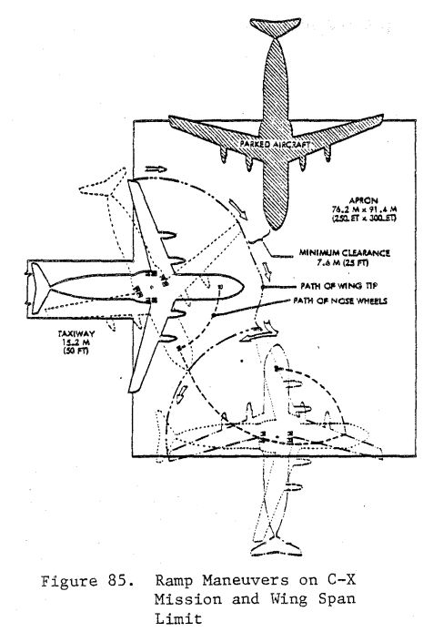
The fourth PDF is a direct comparison of the L-610 cross section to the C-17A, with the C-5A for reference. This shows that the L-610 had a slimmer cross section (lower drag) with a similar (and even taller) cargo box. As I mentioned previously, cargo box dimensions and max cargo weight requirements were not directly specified in the C-X RFP. Bidders justified their designs as optimized for minimum overall life-cycle cost to do the design mission. That requirement was to fly, using an unspecified number of aircraft, a specified Army mechanized unit 2800 NM (unrefueled) to an austere 3000-foot semi-prepared airfield, carrying a minimum of 100,000 lb of cargo per aircraft. The aircraft size, and therefore number, were constrained by how many could fit at any given time on a fixed size cargo-apron tarmac. (Incidentally, this tarmac size severely limited wing span, driving the heavier C-17A design to employing winglets, always an aerodynamicist's second-choice to increased span when otherwise not constrained.) Lockheed's C-X approach was the L-610 with a design cargo weight of 100,000 lb at a load factor of 2.5 g (max cargo weight of 130,000 lb, at 2.25 g), while McDonnell Douglas opted for the heavier C-17A with a design cargo weight of 160,000 lb (max of 170,900 lb).

The fifth PDF is a direct comparison of the L-610 cross section to the proposed C-130WBS ("Wide Body STOL"), an alternative proposal during the AMST days. This graphic shows how the Bradley Infantry Fighting Vehicle was a dimensional driver for tactical airlifter designs in the 1970s and 1980s.

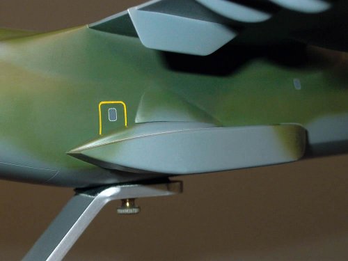
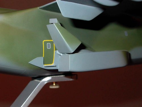
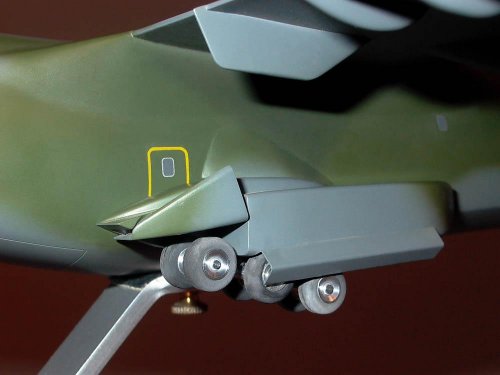
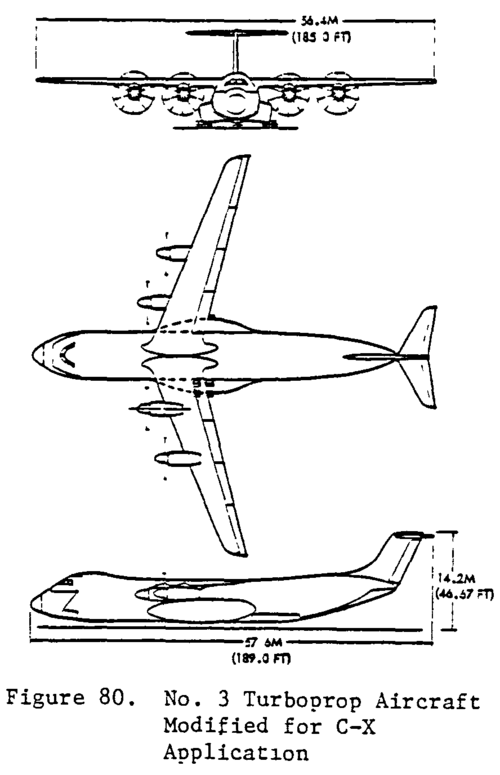
The sixth and final PDF of this post highlights another design tradeoff featured in the L-610. The main landing gear (a "high flotation" design featuring eight wheels on each leg) was housed completely external to the fuselage pressure vessel. The weight savings in fuselage structure offsetting the greater drag of the more pronounced landing gear pods ("wheel well fairings" would be a misnomer, since there was no "well" inside the fuselage for the main landing gear). The main landing gear bogie is actually two trailing-arm levered suspension units back-to-back on one leg. That allowed for maintenance on the ground (tire changes and brake work) by self-jacking. One levered arm could be raised under its own power, independent of the other, to lift four of the eight wheels off the ground without having to place the whole aircraft on jacks.

I have a few overall comments for one more post.
 

Attachments

  • L-610_Cargo_Box_Flexibility_PDF.pdf
    675 KB · Views: 125
  • L-610_Fuselage_Cross_Section_Details_PDF.pdf
    253.4 KB · Views: 84
  • USAF_Airlifter_Cargo_Box_Dimensions_PDF.pdf
    494.3 KB · Views: 96
  • L-610_Cargo_Box_w_C-5_C-17_PDF.pdf
    278.6 KB · Views: 81
  • Fuselage_cross_sections_L-610_C-130WBS_PDF.pdf
    370.8 KB · Views: 92
  • L-610_MLG_Arrangement_PDF.pdf
    415.6 KB · Views: 85
Upside, CX pilots would surely welcome that third engine's centre-line thrust for short / high / hot work.

And 'podding' those wheels outside the shell provides valuable internal volume and weight reduction.

Downside, c/g issues are becoming apparent, with so much over-hang, even the wheel pods --AKA 'Gotta be there'-- blocking access / egress etc etc.

I'd say the design was about to spin off into 'cannot close loop' hell...
 
I found this NASA paper Turboprop cargo aircraft systems study from 1981 that has prospective civilian turboprop design modified for the C-X mission since the idea of dual-role civilian-military design was popular at the time. The full paper includes the "C-X specifications were reviewed to determine those most pertinent to this analyses; they are summarized in Appendlx O." which can be found on pg 226. It also includes a number of diagrams detailing some of the constrained ramp manoeuvres Hank was talking about regarding C-X requirements.

Link to the document
https://ntrs.nasa.gov/citations/19820008197

Direct link to the pdf
https://ntrs.nasa.gov/api/citations/19820008197/downloads/19820008197.pdf
 

Attachments

  • CX19820008197-104A.png
    CX19820008197-104A.png
    30.4 KB · Views: 88
  • CX19820008197-104B.png
    CX19820008197-104B.png
    41.7 KB · Views: 86
  • apron.PNG
    apron.PNG
    76.2 KB · Views: 95
Its interesting to see Boeing's 3-engine. Had to be long term cost-effective going 3 vs 4 engines.

Surprised by this timeframe there wasn't a WIG-like option, with engines over stub wings to keep the engines nearer the COG. Stub wing mounts are lower to the ground, keeping it within reach with less specialized equipment. Maybe wouldn't have added lift at high AoA takeoffs that they do to evade MANPADS coming out of bases in warzones. If Boeing's concept was anything like DC-10, high AoA takeoffs were not a problem.
 
Back
Top Bottom