- Joined
- 26 May 2006
- Messages
- 32,683
- Reaction score
- 11,907


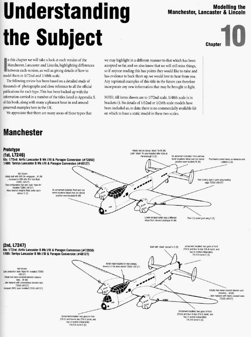
You don't happen to have a copy do you?Flight 1942, p. 557. Apparently.
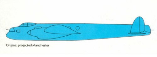
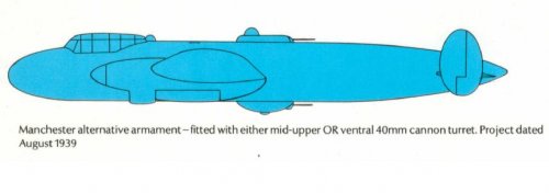
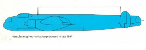
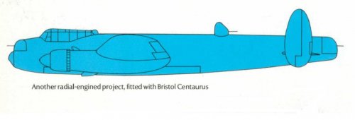
Sabre in place of Vulture? For something really different, replace the Vultures with W3420s?Of course by the time you get into "four-Merlin Manchester" territory, it becomes something else we all know and love, and a four-Hercules version effectively becomes what we now call a Lancaster II. If you want the Manchester to stay a Manchester you really have to keep to the big twin platform, in which case the twin-Hercules-powered version risks being on the anaemic side. The Centaurus is a different beast altogether, of course; it's got the power and growth potential, if only you can get it into the airframe in time for the platform to be useful, but did anyone ever consider the Griffon in place of the Vulture?
Ultimately the true twin-engined heavy bomber concept seems to have been something of a flop. At least A V Roe were able to recast their design with the four engines it really needed and get it into service, which is more than poor old Ernst Heinkel ever got to do with the He 177.
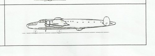
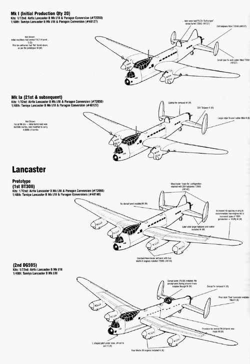
The book Avro Manchester. The Legend behind the Lancaster has copies of the drawings in the tender submitted by Avro. One of those shows the two torpedoes carried on the centreline one behind the other with what looks like monoplane Air tales attached. It can be seen on the Kindle preview on Amazon.An interesting feature of the Manchester and later the Lancaster was the long bomb bay. Specification P.13/36 called for a twin-engine monoplane which was to be capable of carrying, amongst other things, two 18 in (457 mm) torpedoes. Has anyone actually seen drawings or photos of the Manchester carrying said torpedoes?
I wish, quoted in Wiki, I did look for it but as far as I can see the archive is unavailable.You don't happen to have a copy do you?Flight 1942, p. 557. Apparently.
Hmm, maybeFlight 1942, p. 557. Apparently.
The book Avro Manchester. The Legend behind the Lancaster has copies of the drawings in the tender submitted by Avro. One of those shows the two torpedoes carried on the centreline one behind the other with what looks like monoplane Air tales attached.

More likely it's continuation of the deliberate torpedo attack role of the Wellington.I can see a long-range, maritime patrol carrying torpedoes in case it discovers an enemy ship a long way off shore.
")
The book Avro Manchester. The Legend behind the Lancaster has copies of the drawings in the tender submitted by Avro. One of those shows the two torpedoes carried on the centreline one behind the other with what looks like monoplane Air tales attached.
Thanks - I actually have that book and totally forgot to check. Here is the image in question.
View attachment 643093
I've often wondered about the torpedo capability being kept, and indeed taken forward with the Lancaster. Imagine a Lancaster coming in low and fast to drop torpedoes...
Re the torpedo carrying Wellingtons there appears to have been a number of torpedo carrying configurations with two torpedoes.The book Avro Manchester. The Legend behind the Lancaster has copies of the drawings in the tender submitted by Avro. One of those shows the two torpedoes carried on the centreline one behind the other with what looks like monoplane Air tales attached.
Thanks - I actually have that book and totally forgot to check. Here is the image in question.
View attachment 643093
That suggests a slightly different bomb bay for torpedo carrying than bomb carrying.
In terms of the numbers of torpedoes carried, 'The RAF and Aircraft Design: Air Staff Operational Requirements 1923 to 1939' says that initially it was suggested that the new medium bomber (P.13/36) should be designed to carry 4 torpedoes. However, this was questioned by the Coastal Command rep who pointed out this would make a very big, expensive aircraft so the requirement was dropped to 2 and even 2 18" caused problems when the designs came to be drawn up.
In May 1937, the Operational Requirements branch said they had new information on torpedoes and 'it was found that the Avro P.13/36 could only carry one internally, and in any case existing torpedoes could not be released at 150mph from 200ft.'
I would assume that if carried externally it could carry two as with the Wellingtons.

 www.britmodeller.com
Substitute bouncing bombs for torpedoes and that's basically The Dam Busters.I've often wondered about the torpedo capability being kept, and indeed taken forward with the Lancaster. Imagine a Lancaster coming in low and fast to drop torpedoes...
Re the torpedo carrying Wellingtons there appears to have been a number of torpedo carrying configurations with two torpedoes.The book Avro Manchester. The Legend behind the Lancaster has copies of the drawings in the tender submitted by Avro. One of those shows the two torpedoes carried on the centreline one behind the other with what looks like monoplane Air tales attached.
Thanks - I actually have that book and totally forgot to check. Here is the image in question.
View attachment 643093
That suggests a slightly different bomb bay for torpedo carrying than bomb carrying.
In terms of the numbers of torpedoes carried, 'The RAF and Aircraft Design: Air Staff Operational Requirements 1923 to 1939' says that initially it was suggested that the new medium bomber (P.13/36) should be designed to carry 4 torpedoes. However, this was questioned by the Coastal Command rep who pointed out this would make a very big, expensive aircraft so the requirement was dropped to 2 and even 2 18" caused problems when the designs came to be drawn up.
In May 1937, the Operational Requirements branch said they had new information on torpedoes and 'it was found that the Avro P.13/36 could only carry one internally, and in any case existing torpedoes could not be released at 150mph from 200ft.'
I would assume that if carried externally it could carry two as with the Wellingtons.
1. Internal side by side (possibly with modified bomb doors deepening the fuselage)
2. Internal with MAT with aft end of bomb bay modified.
3. Centreline one above the other, which no one seems clear how it would work!
There was a discussion here with a link to a Pathe film from the Middle East showing Wellingtons being loaded with torpedoes in 1942 and the bomb doors being closed up.
Wellington Torpedo Bombers.
I am trying to find pictures of Wellingtons with 2 torpedoes fitted, did they run the centre bomb door or was that removed, I have a copy of the Wellington bomb load diagram that was on an earlier thread which shows the 2 x torpedoes attached to a bomb carrier beam and what looks like no centre d...
Re the torpedo carrying Wellingtons there appears to have been a number of torpedo carrying configurations with two torpedoes.
1. Internal side by side (possibly with modified bomb doors deepening the fuselage)
2. Internal with MAT with aft end of bomb bay modified.
3. Centreline one above the other, which no one seems clear how it would work!
There was a discussion here with a link to a Pathe film from the Middle East showing Wellingtons being loaded with torpedoes in 1942 and the bomb doors being closed up.
Wellington Torpedo Bombers.
I am trying to find pictures of Wellingtons with 2 torpedoes fitted, did they run the centre bomb door or was that removed, I have a copy of the Wellington bomb load diagram that was on an earlier thread which shows the 2 x torpedoes attached to a bomb carrier beam and what looks like no centre d...
Thanks - I actually have that book and totally forgot to check. Here is the image in question.
If you look carefully at the cross section with torpedoes, they seem to be fitted with “wings”.Thanks - I actually have that book and totally forgot to check. Here is the image in question.
Interesting diagram, but I'm curious about the location of the torpedoes fore and aft. The bay is around 33 feet long, yet in line with what P.13/36 stipulates, and I quote: "18" diameter 18' 2 1/2" length with a special tail portion...", I would have thought the load would have been alongside each other, not as depicted here. Clearly the torpedoes are shorter than 18 feet, but fitted with the 'special tail portion', surely side by side makes better sense?

 weaponsandwarfare.com
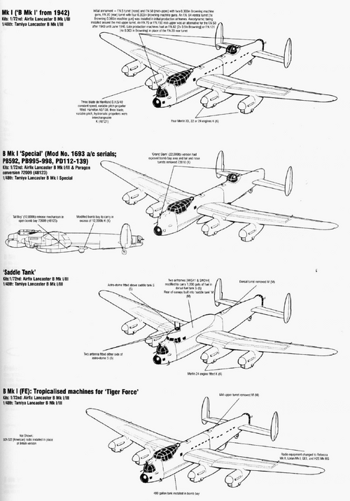
Once you have a winged torpedo it becomes difficult to fit them in the bomb bay side by side, hence the need for a very long bomb bay to carry them one behind the other. The torpedo requirement was dropped in mid-1937, too late for changes to the Manchester design. That change however did happen in time for it to be taken into account by Handley Page when it was redesigning the twin Vulture engined HP.56 as the Merlin engined HP.57 Halifax. So that aircraft could have a much shorter bomb bay.
n the Wellington, the rear of the bomb bay had to be cut away to accommodate a torpedo with a MAT. Whether they could then only carry one torpedo, I’m not clear about.
I take the bomb bay actuator struts to be the diagonal fixtures that appear in both drawings (they appear under the bomb load in the other drawing). That leaves the horizontal "struts" that only connect to the circular torpedo and the vertical lines that penetrate into the fuselage above. The latter don't appear in the bomb load drawing. That suggests that they are something unique to torpedo carriage.Are we sure that the Manchester drawing actually shows wings on the torpedoes (MAT type or not)? Nothing of the sort is visible in the side view, as noted above. When I looked at the cross sections, I assumed that the "wings" in the torpedo version were actuator struts for the bomb bay doors in closed position, shown in open position in the cross section of the bombed-up version.
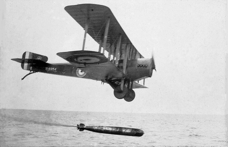
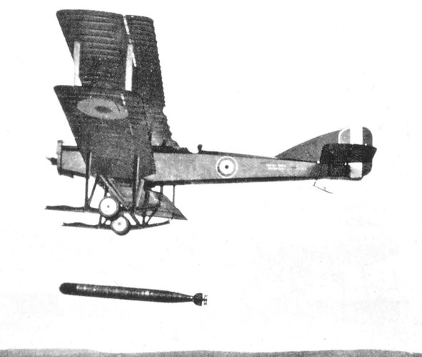
Already have. I asked the same question in my reply to your answer. Interesting to ponder this Ewen, but the illustration clearly shows two torpedoes only being carried, not four as in the front view there is only the one. The torpedoes in the illustration look around 13 feet long each and are likely to be 18-inch ones. This length is shorter than standard and the only thing I can equate it to is this one in the illustration below of a Sopwith Cuckoo, which is shorter than the standard Mk.VIII torpedo in use at the time.But can I turn that question on its head for a moment. Why was there a need to fit the torpedoes one behind the other in the first place?