- Joined
- 9 October 2009
- Messages
- 19,975
- Reaction score
- 10,470
Yes. The best they could do (and what they should have done already) would be to go back and look at the old 1990s CGBL study. And even that would just be a stopgap.

These two links might be useful for this conversation:
Revisiting DDGX/DDG-51 Concept Exploration
Methods for Naval Ship Concept and Propulsion Technology Exploration in a CGX Case Study
Both give a rough idea for what was being considered in terms of the range of capabilities considered for the Arleigh Burkes and CG(X).
They choose to produce one of the 1989 Flt 3 designs? Do you have a link or something ?Having checked both "The CGBL – a Product Improved Version of the CG 52 by Philip Sims" and NAVSEA's DDG-51 Flight III development, I can confirm that the CGBL is considerably bigger than a Burke, even the hull-plugged ones considered for the Flight III (of 1989 vintage).
The CGBL has a Length Between Perpendiculars of 620ft, a Beam of 69ft and deep displacement of 13,675 tons.
Meanwhile the Flight I and II Burkes have identical dimensions of 466ft LBP, a Beam of 59ft, and deep displacements of, respectively, 8313 tons and 8473 tons (this is from the NAVSEA document, and will likely have increased in service)
The Level I Flight III (essentially a repeat Flight II) design had an identical length to Flights I and II, with beam slightly increased to 59.32 ft. Deep Displacement was 9155 tons.
The Level II Flight III (the one ultimately chosen before the end of the Cold War killed off the initial attempt at a Flight III) had a pair of hull-plugs (a 12ft plug forward, and a 28ft plug aft) increasing LBP to 506ft, Beam to 59.50 ft, and Deep Displacement to 10,710 tons.
The highest-risk Level III Flight III design had a single, 46 ft long parallel middle body hull-plug, increasing LBP to 512ft, Beam to 59.8ft and Deep Displacement to 11,896 tons.
CGBL was considerably larger than even the largest, highest risk version of the Burke Flight III conversions. It should be noted that CGBL was never intended to be built, but was intended to provide a viable baseline against which future cruiser designs could be compared. For example, it had full design and construction
margins plus service life reserves, in spite of the fact the it had an existing and low-risk combat system that was unlikely to increase in weight or volume. This unrealistic level of design margin ironically probably means it is considerably superior to any Burke-derived design in terms of margins for future additions.
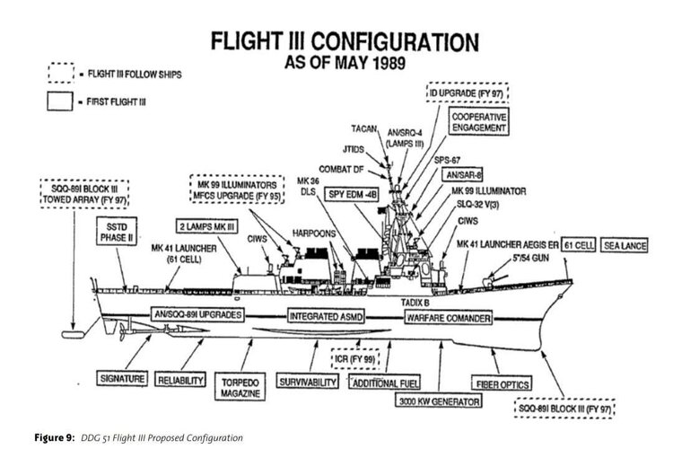
Here it is.Does anybody still have this document?DDG 51 Flight III Design Development white paper from 1989 via MihoshiK at NavWeapons.com:
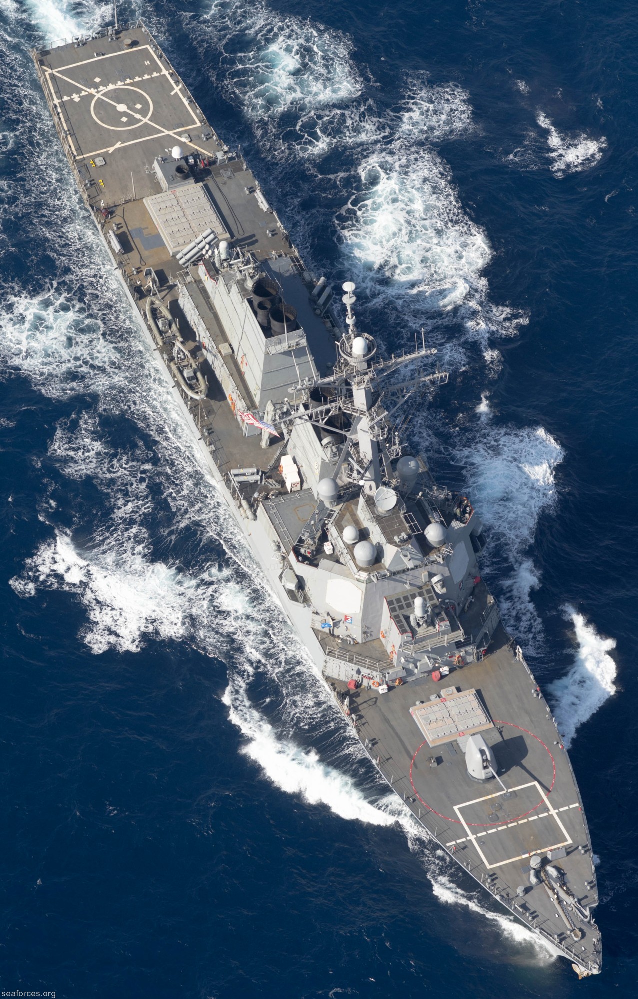
Presumably, it was part cost-saving measure, part the fact that the ships they were replacing (Leahy-class CGs, Farragut/Adams DDGs) did not include a hanger either. Where the hanger currently is is where the aft VLS, Harpoon missiles, and torpedo tubes were on the Flight I/II ships; the torpedo tubes and missiles were retained on the Flight IIAs but not the Harpoons.What was the logic behind not including a helicopter hanger in original Flight I and II Burkes? Was that space ever used for anything on those ships? Seems like they could have put another 5" gun there or more VLS cells.
What was the logic behind not including a helicopter hanger in original Flight I and II Burkes? Was that space ever used for anything on those ships? Seems like they could have put another 5" gun there or more VLS cells.
According to Electric Greyhounds which goes into the difference between the Spruance and Burkes a hanger was consider unneeded.Presumably, it was part cost-saving measure, part the fact that the ships they were replacing (Leahy-class CGs, Farragut/Adams DDGs) did not include a hanger either. Where the hanger currently is is where the aft VLS, Harpoon missiles, and torpedo tubes were on the Flight I/II ships; the torpedo tubes and missiles were retained on the Flight IIAs but not the Harpoons.
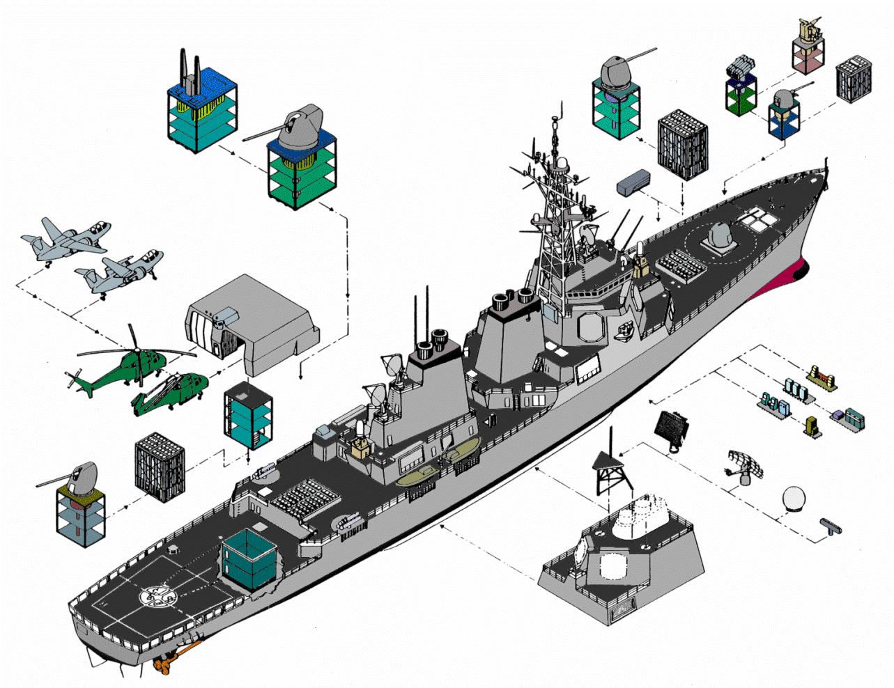
Looks to be some kind of gas turbine generator given the large exhaust.Unfortunately I have no idea what that odd structure just to the aft the rear VLS array is.
First time I saw it I thought it was a fan art but it has been used in talks like this one from the Naval Postgraduate School in 2006 https://www.slideserve.com/nerice/the-history-of-modular-payload-ships-1975-2005Now if you believe this image:
^ThisQuestion:. Do we really need to fill up a thread about DDG-51 projects (concepts, unbuilt designs, etc) with routine contract announcements for ship maintenance?
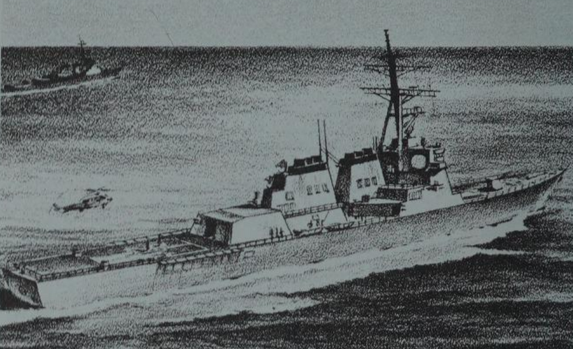
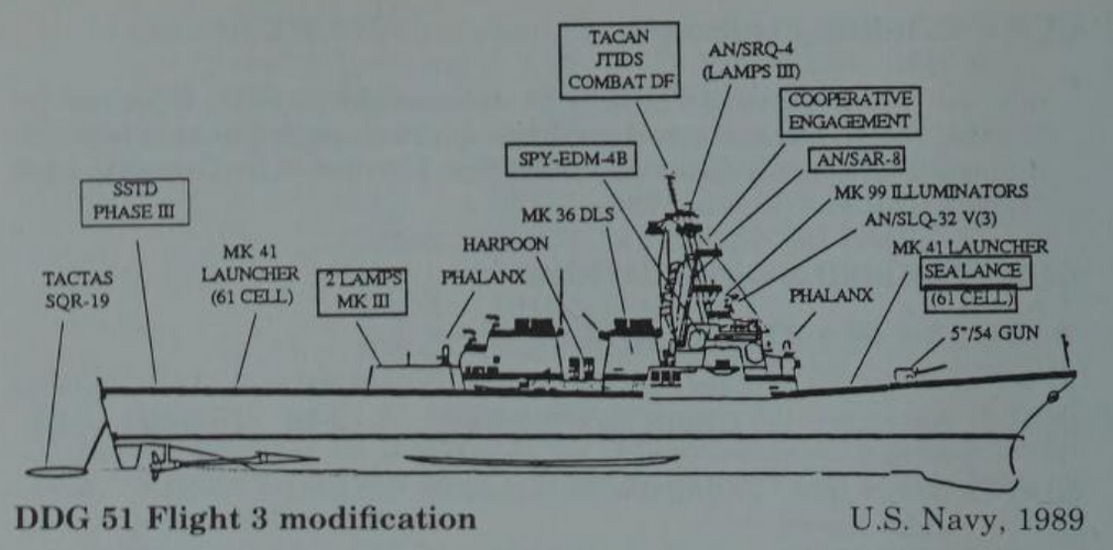
What are these from?An artist's impression and layout drawing of the proposed Flight III in 1989.
I don't think there is a book for 89/90, 14th edition is 87, 15th is 1993.The Naval Institute Guide 1989/90 I think.
Looks like it has most of the features of the Level II design, with further options for adding some Level III design capabilities on later ships (Improved SQS-89I Block III from FY97 onwards, Intercooled-Regenerative Turbines from FY99 onwards)Another drawing of the Burke Flight III, from a 2009 NEJ article called "Getting AEGIS to Sea". It says Flight III Level II was selected, but shows the giant sonar dome, which was a Level III change. However, It doesn't explain why, so I'm a bit puzzled.
In all likelihood it been the same.Any guestimates on price compared to original price if Arleigh Burke had been to Flight III specs in terms of armement fit from the start - 61/64 cell VLS fore and aft, 5" gun forward, Phalanx fore and aft and hanger and flight deck for two LAMPS 3?
Definitely not worth it, then, that's 2/3rds of the missiles!Stumbled across a very brief summary of a 2008 MIT student project to study the feasibility of retrofitting Flight I Burkes to accommodate LCS mission modules. In very brief, it's doable, at the expense of the aft 64-cell VLS, the towed array, and a CIWS.
Not really. Unless you stuff some submarine-size Mk48 tubes in there instead... Which was apparently a thing for a while in the 1970s and into the early 1980s on design studies. Yes, blew my mind, too.lol did not know that but okay............... but im saying like is there anything better or more updated that they could put on there???Why? They're perfectly good at making surface ship warfare officers think they can do something about submarines, and don't cost too much for something that's essentially a decoration.are they ever going to get rid of or replace the mk 32 tri tube torpedo launchers?
Even one professional journal outside my own specialty makes my wallet weep for mercy...These two links might be useful for this conversation:
Revisiting DDGX/DDG-51 Concept Exploration
Methods for Naval Ship Concept and Propulsion Technology Exploration in a CGX Case Study
Both give a rough idea for what was being considered in terms of the range of capabilities considered for the Arleigh Burkes and CG(X).
Wish Naval Engineers Journal wasn't so expensive.
Wrong Flight III. PMN1 is referring to the original late-80s Flight III, killed off by the Peace Dividend and replaced by the Flight IIA.In all likelihood it been the same.
Cause the Restart has been a noted FURBAR due to having to basically restart multiple lines, like the MK41, and need to redesign multiple parts from the Propeller shaft sealling to power plants just to replace the parts who OG companies of the B1&2s went out of business.
To say nothing of the basically 11 hour redesign of the vessels after the second one to Fit the Spy6 and all the new gear.
I honestly doubt it came out cheaper or "safer" than keeping with the Zumwalts or the OG Block 3 design.
It's fairly likely that in the design work which led to the Level I/II/III designs, the ship impact of each individual capability option was assessed.The Level III design had some fairly significant alterations compared to the original Burke design, including a new hull design aft with two skegs, a hull plug of 46ft and box girders running a significant proportion of the ship's total length, so adding the some of the new systems onto the Level II hull later on in production may not have been as risky as going ahead with the new Level III hull.
Hi there.Here it is.
Just tried it, works for me? And I tried from a different PC from which it was uploaded?Hi there.
For some reason when I tried to open the file it said the pdf could not be loaded.
Could you repost this file, again, by any chance?
Works for meHi there.
For some reason when I tried to open the file it said the pdf could not be loaded.
Could you repost this file, again, by any chance?
Hi there.
For some reason when I tried to open the file it said the pdf could not be loaded.
Could you repost this file, again, by any chance?
 www.thedrive.com