
You are using an out of date browser. It may not display this or other websites correctly.
You should upgrade or use an alternative browser.
You should upgrade or use an alternative browser.
Energia - Buran Space Transportation System
- Thread starter flateric
- Start date
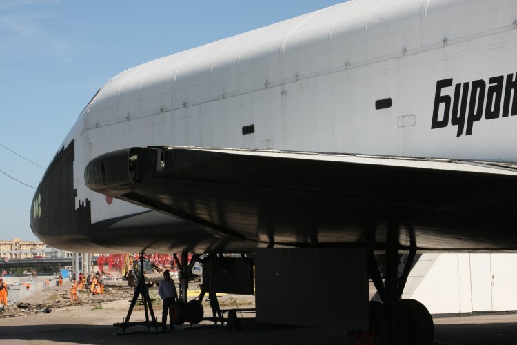
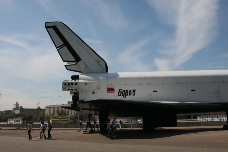
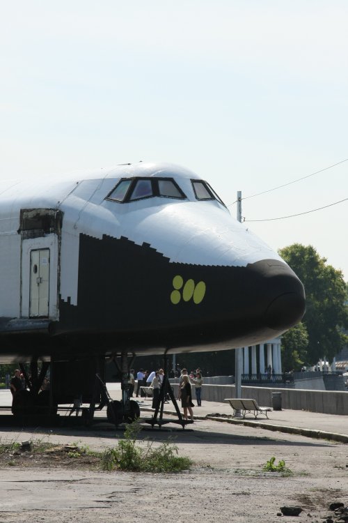
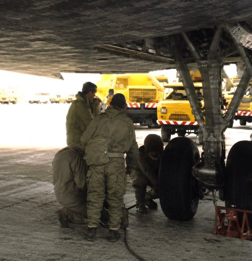
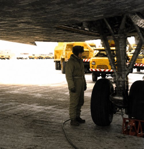
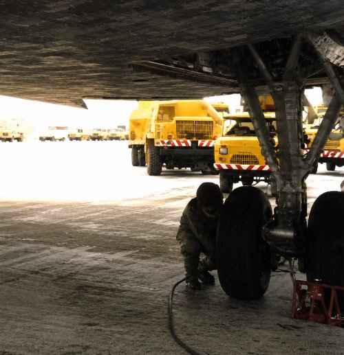
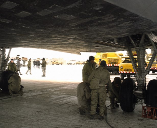
Okay Vadim!I downloaded this video (and many others) from your site many years ago — that’s where these AI-generated images come from. The Buran at VDNKh is literally a beauty. I really hope to visit it one day and take my own measurements!!Here you can see the scale of a person relative to the ship and its landing gear https://www.buran.ru/video/mpg/on_pk_noresize.mp4

Attachments
Last edited by a moderator:

KRRRL
ACCESS: Restricted
- Joined
- 31 July 2023
- Messages
- 24
- Reaction score
- 46
Hello again.
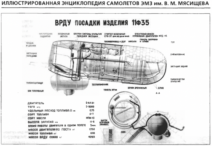
Do you know the maximum mass of the jet fuel for OK-1.01 VRDUs?

galopujacy_jez
Maks
600kgHello again.
Do you know the maximum mass of the jet fuel for OK-1.01 VRDUs?
Attachments
KRRRL
ACCESS: Restricted
- Joined
- 31 July 2023
- Messages
- 24
- Reaction score
- 46
Thanks600kg

Incarn
ACCESS: Confidential
- Joined
- 2 November 2024
- Messages
- 141
- Reaction score
- 842
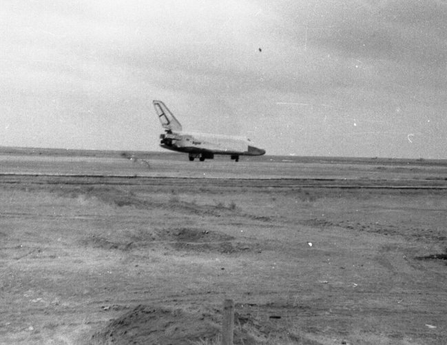
galopujacy_jez
Maks
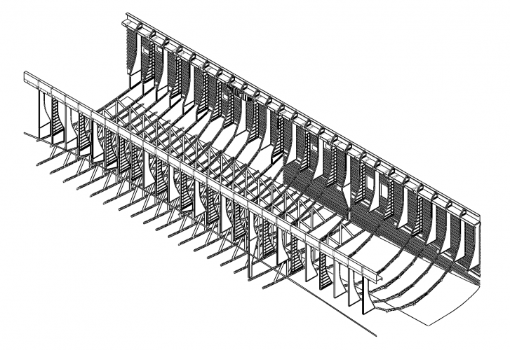
More work on the mid-fuselage structureI was wondering if you have more [...]
Attachments
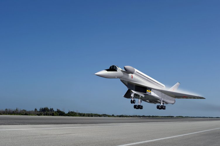
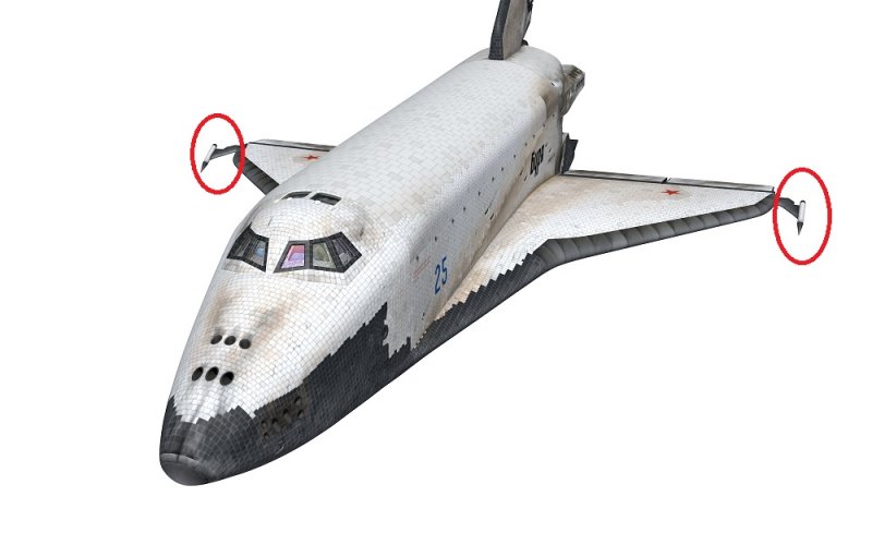
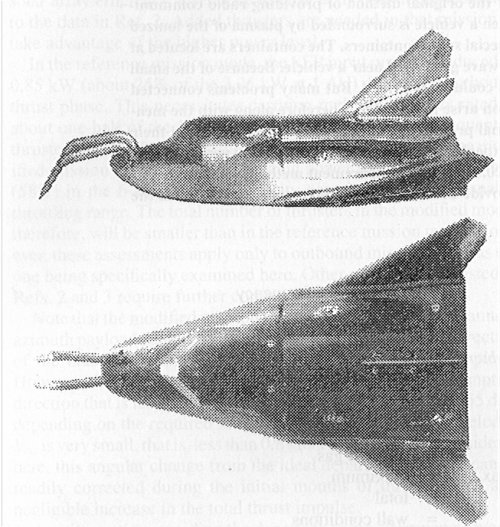
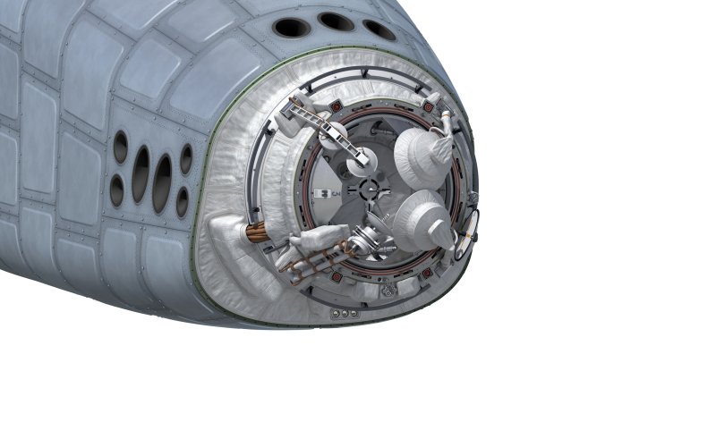
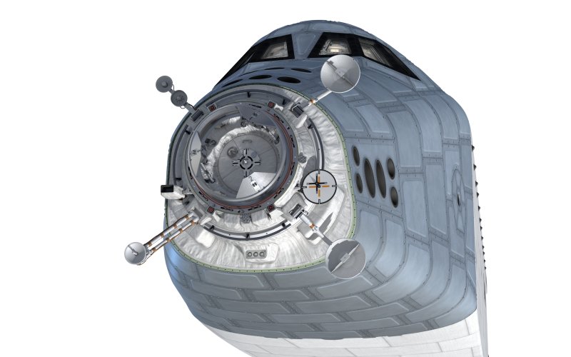
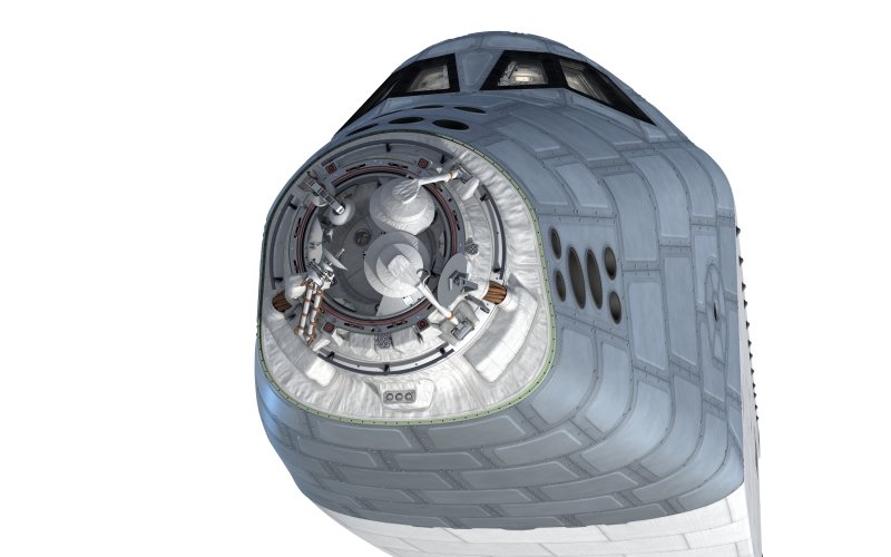
We are continuing to work on the 3D modeling of the “Bolid” combat module, based on the “Buran.”
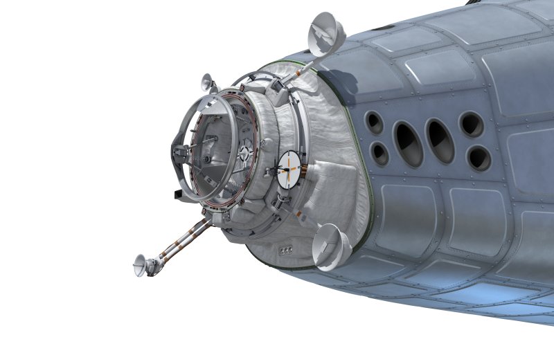
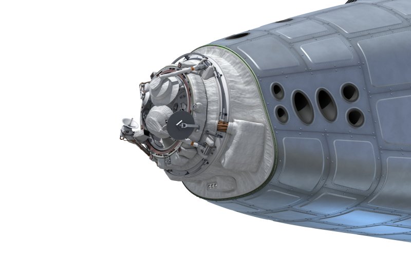
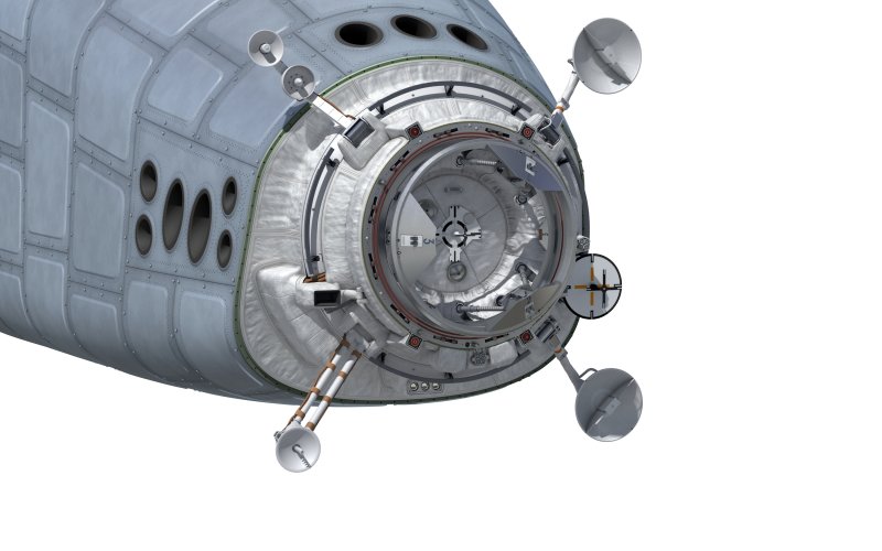
Based on documentation from the Energia Rocket and Space Corporation, the docking unit has been finalized: all approach and docking antennas are in the correct positions and fold away under the jettisonable nose cone.
A docking system on the nose? Do you know why they chose that location? It seems risky to put the heat shield in a location that requires an opening in the heat shield...
KRRRL
ACCESS: Restricted
- Joined
- 31 July 2023
- Messages
- 24
- Reaction score
- 46
This is an expandable module with BOR-based nuclear bombsA docking system on the nose? Do you know why they chose that location? It seems risky to put the heat shield in a location that requires an opening in the heat shield...


- Joined
- 1 April 2006
- Messages
- 12,280
- Reaction score
- 15,100



Incarn
ACCESS: Confidential
- Joined
- 2 November 2024
- Messages
- 141
- Reaction score
- 842
We are continuing to work on improving the docking module on the “Bolid.”
We have added the cut-to-size screen-vacuum thermal insulation, electrical cables, a TV camera for the camera-based approach system, and lighting fixtures:
We have added the cut-to-size screen-vacuum thermal insulation, electrical cables, a TV camera for the camera-based approach system, and lighting fixtures:
Attachments
Last edited by a moderator:
Incarn
ACCESS: Confidential
- Joined
- 2 November 2024
- Messages
- 141
- Reaction score
- 842
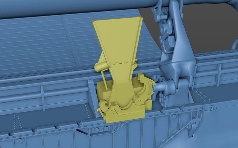
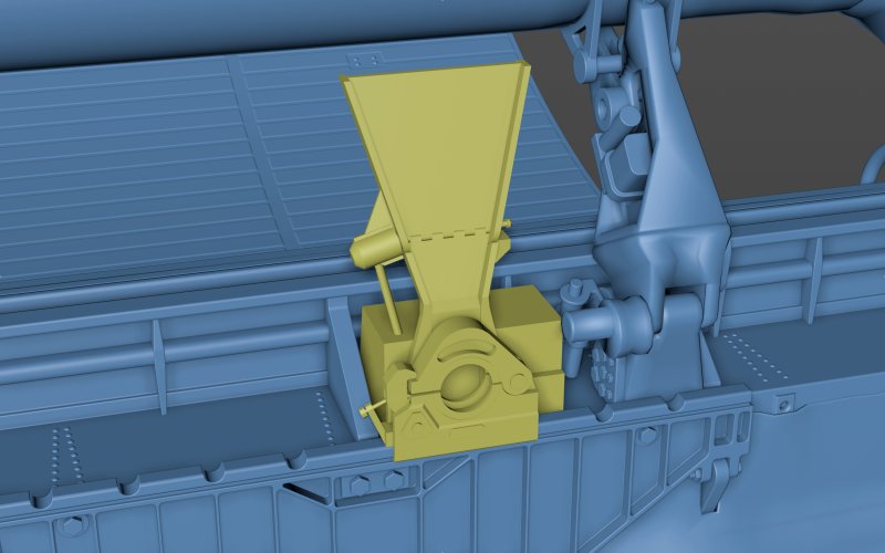
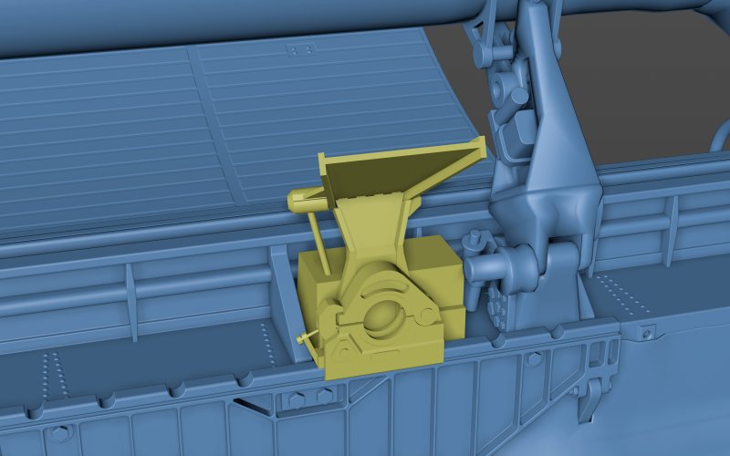
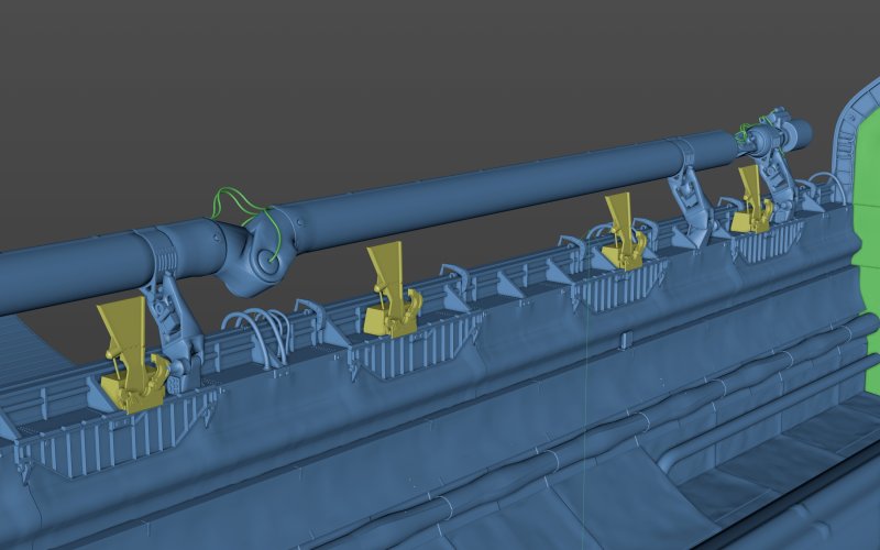
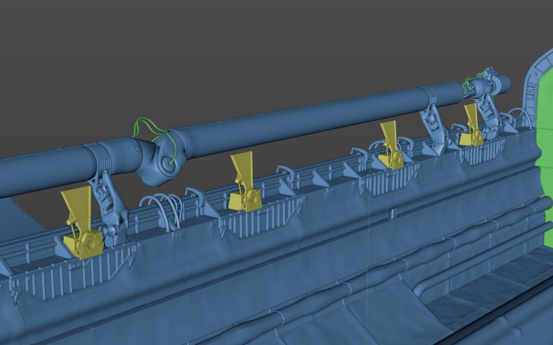
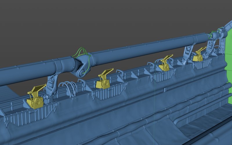
While modeling the “Bolid,” we began working on the payload compartment, while also correcting errors in our “Buran” model.
We’re working from the developer’s drawings, but a problem has arisen—different drawings sometimes contradict each other.
We’re currently working on the active mounting points for payloads that separate during flight. For the parts missing from the drawings (the documentation is incomplete), we’re essentially having to design them ourselves.
Please hold off on criticism for now—everything is still a work in progress))
We’re working from the developer’s drawings, but a problem has arisen—different drawings sometimes contradict each other.
We’re currently working on the active mounting points for payloads that separate during flight. For the parts missing from the drawings (the documentation is incomplete), we’re essentially having to design them ourselves.
Please hold off on criticism for now—everything is still a work in progress))
Attachments
-
 attachment_point_active_2_open_2.jpg2.3 MB · Views: 51
 -
 attachment_point_active_2_open_1.jpg2.3 MB · Views: 52
 -
 attachment_point_active_2_closed.jpg2.3 MB · Views: 50
 -
 attachment_point_active_1_open_2.jpg2.2 MB · Views: 50
 -
 attachment_point_active_1_open_1.jpg2.2 MB · Views: 52
 -
 attachment_point_active_1_closed.jpg2.2 MB · Views: 51
Last edited by a moderator:
Incarn
ACCESS: Confidential
- Joined
- 2 November 2024
- Messages
- 141
- Reaction score
- 842
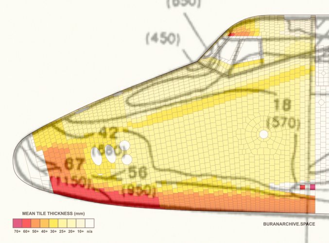
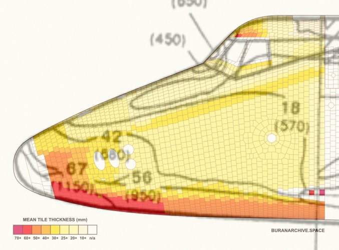
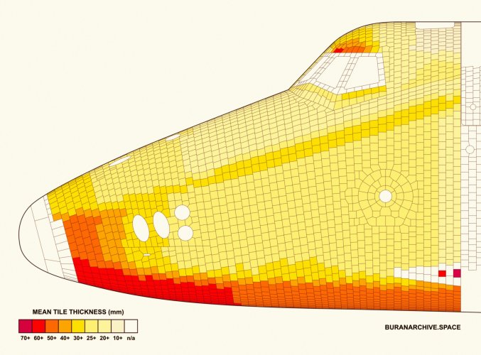 The illustration is highly questionable.
First, the tile thickness is the difference between the outer (aerodynamic) surface, which is still classified, and the surface of the metal frame, which is also classified. Precise data on both surfaces is nonexistent and has never been published anywhere.
Second, the tile thickness in the forward fuselage actually corresponds to the heating temperature (it was published, see the illustration), whereas here we see significant differences between the local maximum temperature and the illustrated tile thicknesses.
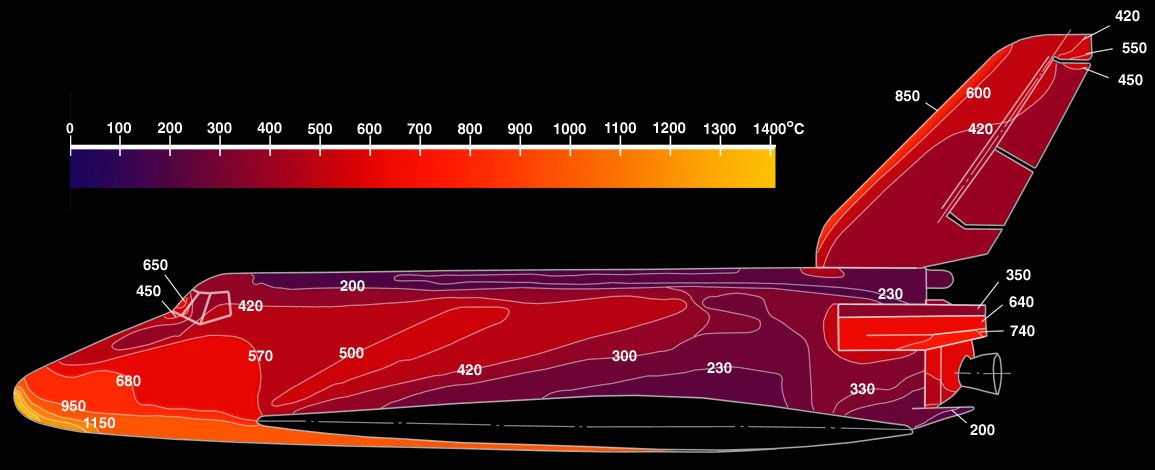
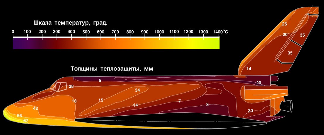
I'm showing the correct tile thickness diagram:
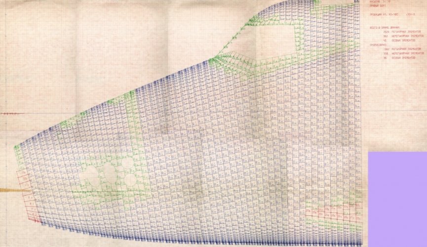
galopujacy_jez
Maks
The data in this printout correlates quite well, though I admit there are some differencesFirst, the tile thickness is the difference between the outer (aerodynamic) surface, which is still classified, and the surface of the metal frame, which is also classified. Precise data on both surfaces is nonexistent and has never been published anywhere.
And vs the illustration in Lozino-Lozinskiy 1997, which your diagram is based on
Incarn
ACCESS: Confidential
- Joined
- 2 November 2024
- Messages
- 141
- Reaction score
- 842
It was precisely on the basis of this comparison that I concluded the aforementioned drawing was inaccurate (or questionable).The data in this printout correlates quite well, though I admit there are some differences
View attachment 821241
And vs the illustration in Lozino-Lozinskiy 1997, which your diagram is based on
View attachment 821246
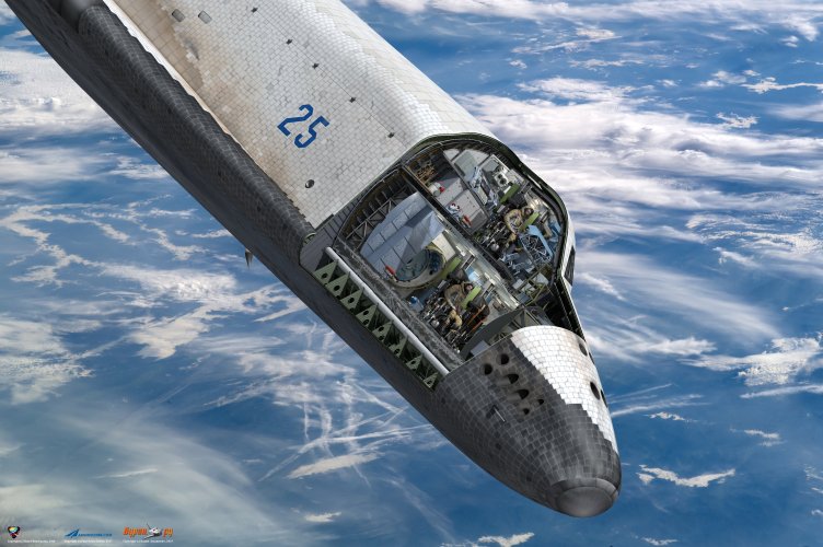
Our 3D model of *Buran* incorporates the most accurate external (aerodynamic) surface geometry ever published. However, only I know its origin and the extent of its deviation from the actual external surface of the real *Buran* orbiter.
Yet, the external surface profile of *Buran's* metal airframe has never been published and remains classified to this day, while the known thermal protection tile thicknesses are merely rough averages.
For this reason, I viewed the presented thickness diagram with considerable skepticism.
Attachments

Last edited:
galopujacy_jez
Maks
What do you think the numbers in the first image I posted represent then? Also keep in mind that the two illustrations we're comparing use different thickness ranges for each color.It was precisely on the basis of this comparison that I concluded the aforementioned drawing was inaccurate (or questionable).
Incarn
ACCESS: Confidential
- Joined
- 2 November 2024
- Messages
- 141
- Reaction score
- 842
I assume the numbers indicate the tile thickness in millimeters, and the colors represent 10-millimeter thickness ranges.What do you think the numbers in the first image I posted represent then? Also keep in mind that the two illustrations we're comparing use different thickness ranges for each color.
galopujacy_jez
Maks
oh, sorry, that's not quite what I meant, I'm simply asking for your opinion on the meaning of the numbers in the tile cut printout. the top two seem to be position (longitudinal grouping of some sort and the index within each group); I assumed the bottom number to be related to thicknessI assume the numbers indicate the tile thickness in millimeters, and the colors represent 10-millimeter thickness ranges.
Attachments

Last edited:
Incarn
ACCESS: Confidential
- Joined
- 2 November 2024
- Messages
- 141
- Reaction score
- 842
I don't know for sure.oh, sorry, that's not quite what I meant, I'm simply asking for your opinion on the meaning of the numbers in the tile cut printout. the top two seem to be position (longitudinal grouping of some sort and the index within each group); I assumed the bottom number to be related to thickness
I can surmise (given the principle of slicing the tiles—much like slicing a sausage into rounds) that the small number in the center represents the slice number from the sausage-style cut, the large number at the top left of each tile indicates the tile's position within that slice, and as for the number with the decimal fraction—we can only guess.
Incarn
ACCESS: Confidential
- Joined
- 2 November 2024
- Messages
- 141
- Reaction score
- 842
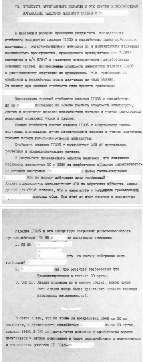
From the final report on the readiness of the 1K11K25 reusable space system for the start of flight tests (Part 4: Testing and readiness for flight tests of the 11F35 orbital spacecraft).
I had to redact some of the content to avoid any issues regarding confidentiality.
The overall conclusion is that ‘Buran’ does not fully meet the requirements for resistance to the effects of a nuclear explosion; however, as a nuclear explosion is not anticipated during the first space flight, flight tests may commence.
I had to redact some of the content to avoid any issues regarding confidentiality.
The overall conclusion is that ‘Buran’ does not fully meet the requirements for resistance to the effects of a nuclear explosion; however, as a nuclear explosion is not anticipated during the first space flight, flight tests may commence.
Attachments
Last edited by a moderator:
Similar threads
-

-
 Black ZEUS: The top secret shuttle mission that never flew
- Started by Flyaway
- Replies: 4
-
-
 Looking for old AWST with articles on soviet military space program
- Started by flateric
- Replies: 12
-
 NPOMash Shchit-2 space-to-space guided missile
- Started by fightingirish
- Replies: 15