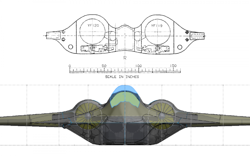
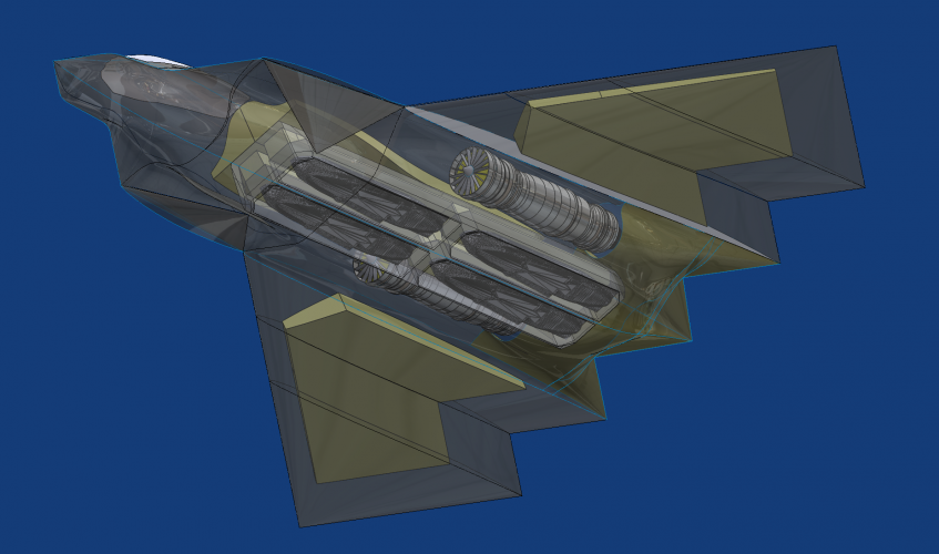
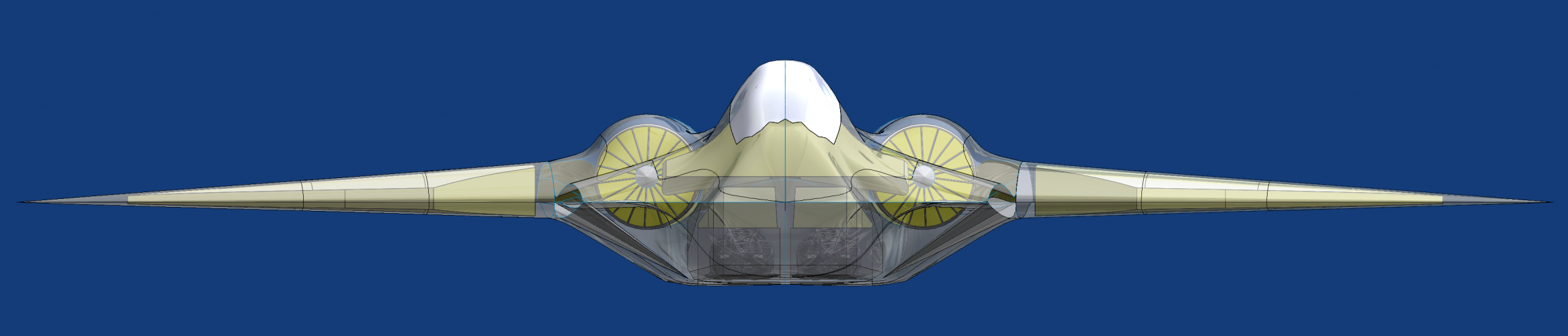
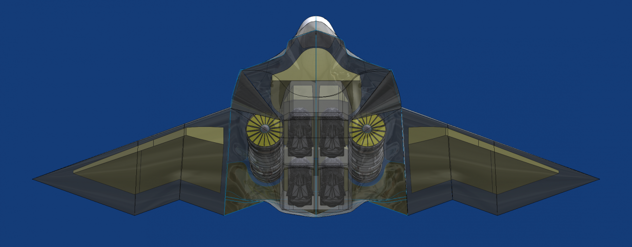
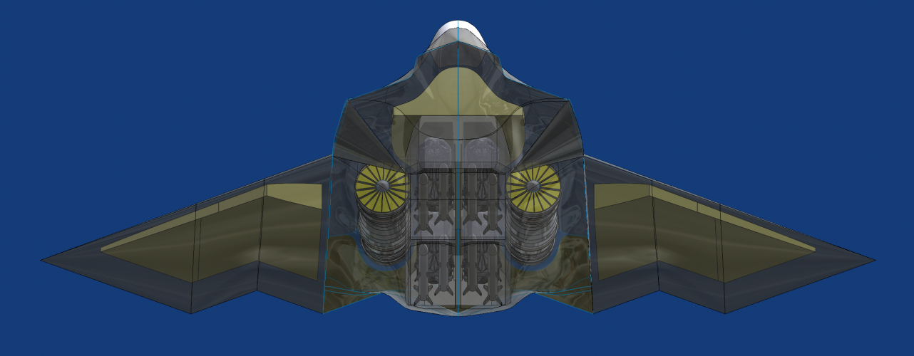
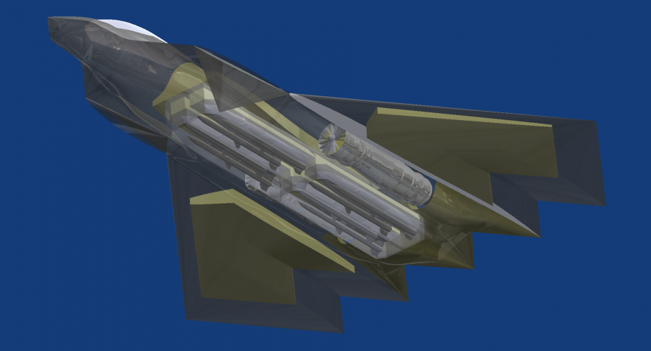
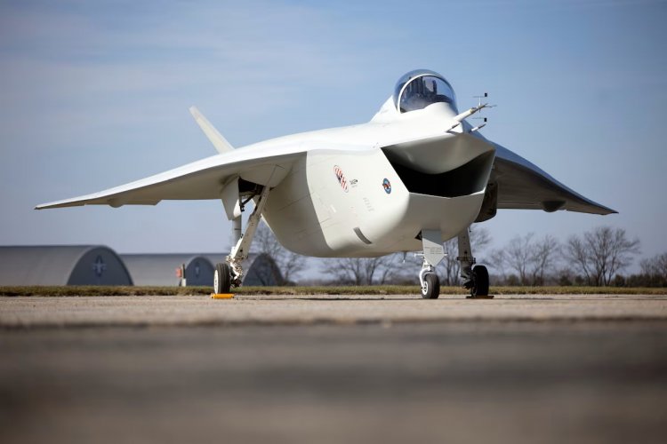
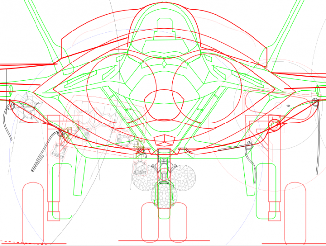
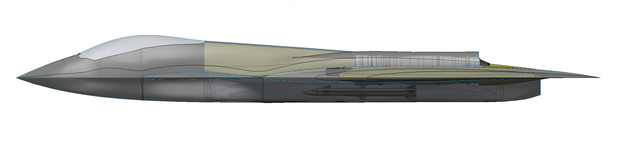
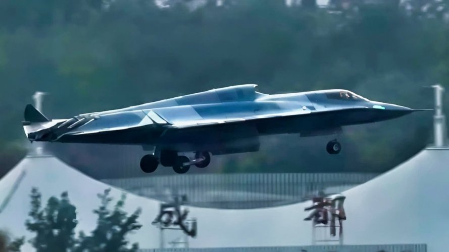
Possible configuration of the Boeing F/A-XX

The AAM bays are positioned very close to and below the engines.
I agree, my preference was to do something different given how ridiculously massive the main bay is (ie. Why bother with side bays when you can carry a hillarious number of Amraam or AIM-260 in the main bays). But I was swayed to try by arguments along the lines of having ability to launch a missile without a major RCS spike (orienting the aircraft away from emitters and opening the shadowed sidebay to release the ordnance). Not saying its perfect but I'll concede getting two pcs in there is not really critical and even so you could have made harsh arguments about needing to package the ejectors etc. I think if you were really taking a long shot against a foe and wanted to release from the main bay you could achieve this in a banked turn just as plausibly. If the target is closer in the arguably the short range shot is more beneficial so if I was in charge (!) I might prefer something else like the Dew and a single short range missile rather than try to cram in the Amraam. It was practical to fit bigger side bays in under the engines but this came with a frontal area penalty. I was literally going back and forth from Openvsp and wave drag calcs back to Solidworks adjusting section areas to tweak the Wave Drag numbers so not making the side bays any larger and accepting you might well critique this was my conscious decision!
 
Furthermore, the airfoil thickness seems somewhat excessive for a supersonic fighter.
It's 6% and the same thickness root and tip percentage as the F-22. This is one of the major benefits of a delta to have such large wing volume (because of an 11m root) specifically for fuel. With the internal weapons back carrying fuel and 4 JASSM and 4 AMRAAM the fuel fraction is still well over 40% specifically because you and all the other guys I respect created such a interesting discussion on the critically of acheving high fuel fraction and this causing a difficult trade off with total volume, magazine depth and supercruise. I don't doubt we could take this, thin the wings, cut 400mm off the bottom of the aircraft and half the weapons bay volume and have a much better aircraft for WWIII in the old Western European theater but there have to be trades and I think I would like to park my carriers as far off the coast as I can. Still a Mach-2 aircraft and frontal area max looks reasonable albeit not a small aircraft.
 
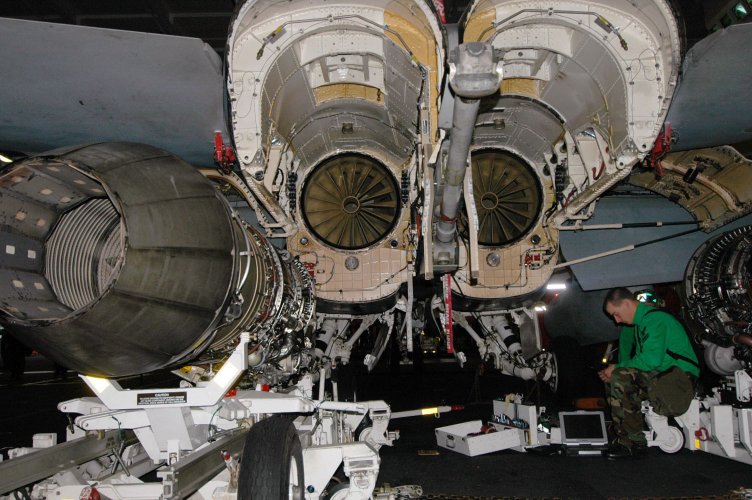
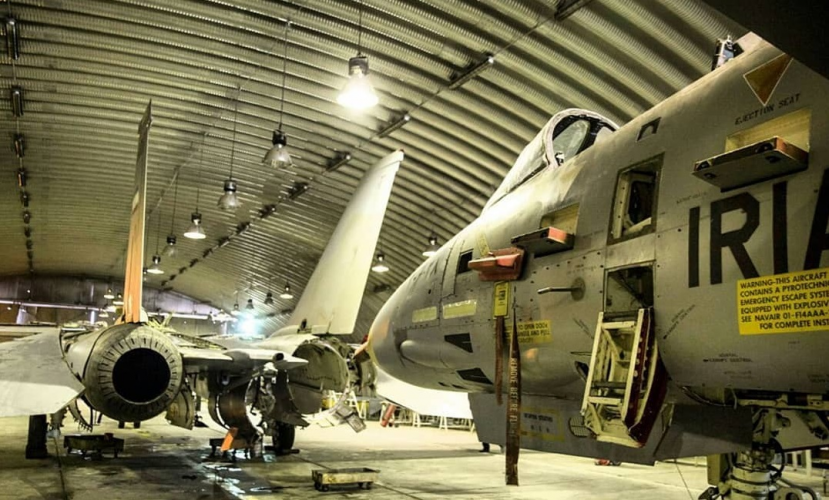
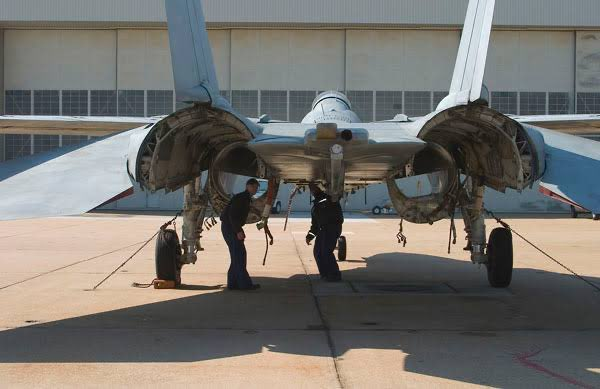
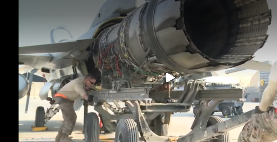
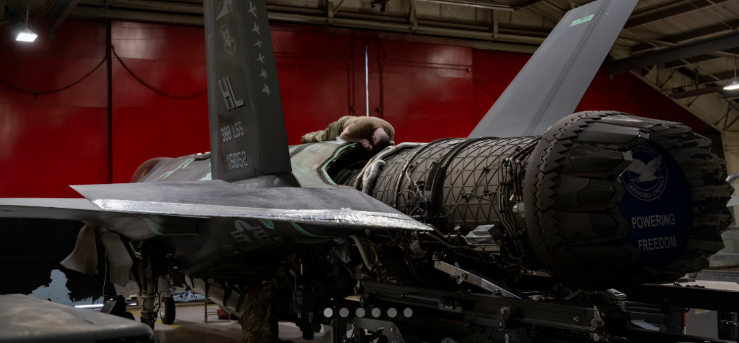
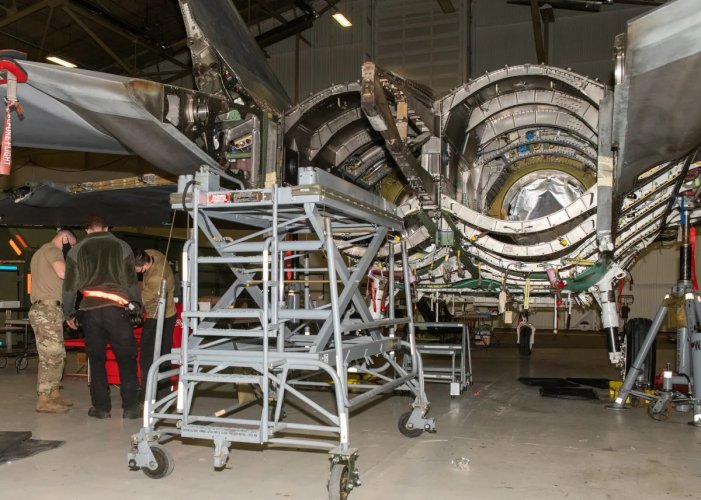
In any case are you sure that engines aren't removed by pulling out from the tail (I wasn't so just watched some videos / forced research(!), pretty sure although access to areas of the engine is needed the actual swap is from the tail at least for F-15, F-14 and F-22. Interestingly although no doubt you know this, the F-14 had a track and roller system to support the engine during retraction so no major bodywork was removed. Surprised the F22 accepted needing panels to be disturbed for this task given the VLO criticality and penalties.
You're half correct. This procedure is common throughout the aircraft industry. The bottom panels have to be opened to disconnect not just the main bolts but also minor ones, network cables, electrics, hydraulics, fuel lines etc. Even though the engine is just pulled out and or inserted it takes 1-2 hours to complete the task.

It's 6% and the same thickness root and tip percentage as the F-22.
I think F/A-XX will have more because it's mostly slower. While I think F-47 is closer to 5% as it's faster. Your choice makes for a thinner wing than mine as I'm using a more "recent" trick seen with NATO research/Japanese F-XX.
The only critique I've here is it seems there are no bulkhead structure within the tanks. So your volume calculation might be off. But this is just nitpicking on details that don't matter as far as art goes. Just see it as a note.
With the internal weapons back carrying fuel and 4 JASSM and 4 AMRAAM the fuel fraction is still well over 40% specifically because you and all the other guys I respect created such a interesting discussion on the critically of acheving high fuel fraction and this causing a difficult trade off with total volume, magazine depth and supercruise.
40% is good. The problem with fuel is how much the fraction of trapped fuel there is that can't be used. And frankly, the real world is pretty harsh here.
What I see as possible problem with your aircraft's internal volume is possible lack of space for other subsystems. It's hard to say with these as they are also custom made. I'm estimating at least 1 m^3 for avionics, maybe ~2-3 m^3 for everything else, not counting radar dome. Hydraulic lines and such also take a lot more volume than they actually occupy, too. Again just a note to keep in mind.

Btw. how many wing stations do you envision it has?
 
I don't think JASSM-ER is in any way related to carriers.
Yes.
It's a reach extender; reach extension is needed if you want to, say, reach Chengdu from bay of Bengal.

For carrier strike, be it stand off or stand in, you may want to use completely different weapons with different properties, and choose sizes accordingly. That is, either go higher/faster/larger, and limiting yourself to bay size(any bay) will mostly be limiting your booster without adding survivability.
Or you may use your survivability and bring more, smaller munitions, closer.
I don't think you understand the problem at the heart of it. I don't want to derail this thread so I'm giving you homework :D to tackle the problem and hopefully in the end you'll see it my way.;)
So before we go into more advanced consideration lets go back to the basics of physics. To move a mass a certain distance you have to spend a certain amount of energy like 1 J/kg. This is linear (we ignore drag loses etc.).
You can consider mass being the payload. Each missile is ofc another layer of the same problem.
At the heart of your argument you say it's doesn't matter as the missiles can be exchanged with another and all is good.
But if you look at the math it doesn't matter. You will spend the same amout of energy for the same amount of payload.
Exchanging for different missile won't solve the mass (as in explosives needed) problem that needed
Now there's something in the military called payload amount a force can deliver per day. This determines how many aircraft are needed to compete.
 
You're half correct. This procedure is common throughout the aircraft industry. The bottom panels have to be opened to disconnect not just the main bolts but also minor ones, network cables, electrics, hydraulics, fuel lines etc. Even though the engine is just pulled out and or inserted it takes 1-2 hours to complete the task.
Agreed, and for this reason access for these tasks via the IWBs or from above (hanging off ropes!)
I think F/A-XX will have more because it's mostly slower. While I think F-47 is closer to 5% as it's faster. Your choice makes for a thinner wing than mine as I'm using a more "recent" trick seen with NATO research/Japanese F-XX.
The depth of my decision making process was I thought it looks pretty thick and blended sufficiently as is so I stuck with 6% but very interesting.
The only critique I've here is it seems there are no bulkhead structure within the tanks. So your volume calculation might be off. But this is just nitpicking on details that don't matter as far as art goes. Just see it as a note.

I agree with you, and the models you and others have created with bulkheads were my original goal but I am too busy. One day I (or someone) can take this forward and flesh out the intakes and bulkhead designs. I definitely can do it fairly trivially, there are 20 aircraft cross sections to loft the oml but I lost to work pressures. I agree and for sure my numbers are approximate in any case. There isnt any great reason to doubt that a very large internal weapons bay which forms almost a large pregnant bulge under the airframe stuffed with fuel won't have a high fuel fraction and this was part of my aims.

40% is good. The problem with fuel is how much the fraction of trapped fuel there is that can't be used. And frankly, the real world is pretty harsh here.
What I see as possible problem with your aircraft's internal volume is possible lack of space for other subsystems. It's hard to say with these as they are also custom made. I'm estimating at least 1 m^3 for avionics, maybe ~2-3 m^3 for everything else, not counting radar dome. Hydraulic lines and such also take a lot more volume than they actually occupy, too. Again just a note to keep in mind.

Btw. how many wing stations do you envision it has?
It's not bad, I should make some sections and share, will get around to this. Out of interest what CAD formats can you take? I can send it to you to draw your own conclusions.
 
It's not bad, I should make some sections and share, will get around to this. Out of interest what CAD formats can you take? I can send it to you to draw your own conclusions.
Almost any format. Solidworks is fine but Ialso have normal 3D modelers so STL, DXL and blender?
 
11) Tank Volumes - Main dorsal tank 6400L, Wing Tanks 4200L per side (it's a 6% root thickness wing with a 11m root). IWB tanks are roughly 4700L total (see highlighted diagram below) and leave most of the lower bay volume free. In this mode either weapons adaptors are interfaced to the tank, or to the side of the keel and weapon bay structure walls, not saying it's easy but it would be flexible.
This would give a standard fuel load of about 14,800L/26,000lbs, and 34,000lbs with the IWB tanks.


You're really designing a carrier strategic bomber aircraft(with all other capabilities coming second to this requirement),
What do you think that the A-6 was? 800nmi range while hauling 4xMk84s, or B61s.
 
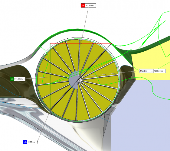
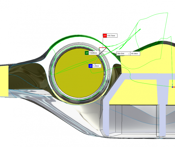
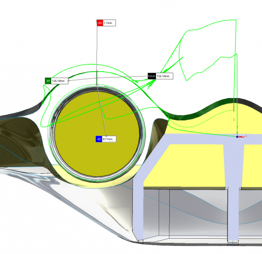
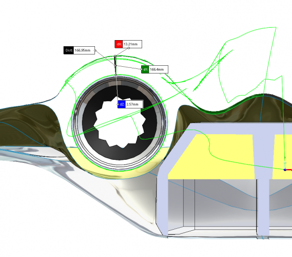
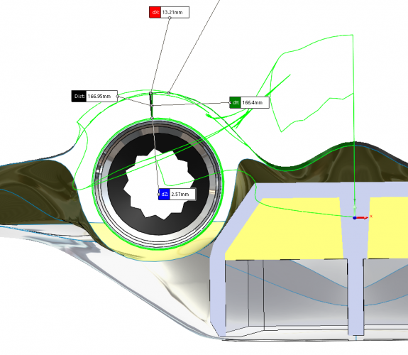
That's deceptive, I recognised all the arguments about the hoops around the engines and I think the front view makes the section depth look strangely less than it is. For what its worth I think the depth minimum is 100-120mm there. That's an important area for real acting the loads with all the trade offs in frontal area and packaging. It's tight, no question but it wouldn't increase by much if at all in a real design. Unless you are a chief engineer with 20 years experience leading structures teams in which case please educate away!

Ps. I am a 30year qualified engineer who is MD, Technical Director and founder of a manufacturing business in the UK that makes very high performance electric motors / propulsion systems (electronjcs, software, housings, cooling, structures the whole shebang) for Automotive, Aerospace and Motorsport. I realise I'm putting myself up on the parapet here so I didn't want to embarrass myself hence the reticence in sharing this model in the first place I really appreciate the critique but I'm going to squirm and wrestle back, hope you're OK with that

Obviously my statements are not based on practical experience (designing fighter jets), but rather on observation and comparison with similar aircraft (e.g. the (Y)F-23). In my opinion, this is a practical approach for what we are doing here.

Having said that, I still believe it's too tight. And especially for a carrier-based fighter jet, it's most likely an essential requirement to be able to remove/install the engines from below (Due to the limited space in the hangar. And the carrier's movements make the use of a crane rather impractical).... However, I'm fine if you have a different opinion.

FA-XX_jmspeedfreak_003.PNG
F-18_fan blocker_01.jpg
 
Last edited:
Thanks VTOLicious, I didn't know that the F404/F414 engine leaves the IGVs in place. Cool (and kind of helpful since that area is potentially a tight clearance area given the engine diameter often seems to neck down a bit after the front fan area.

In any case, I apologise, I knew the F-14 used the track rail but didn't appreciate it also did this.

1779016026261.png

I'm surprised how much structure is gone once the access doors are opened. Learn a new thing everyday. Some references I found discuss that the engine slides back, and then rotates downward. Sounds hard in bad weather!

1779016110761.png
It's not clear if the rest of the hoop around the engine is structural or not. I haven't found a clear answer. And in any case designing a structure to be efficient in passing loads like these through a joint is not trivial. Anyway I also now know more about F-14 engine removal procedures than I ever wanted to!

The F-16 and F-35 do however appear to do a straight out the back retraction after apparently removing some panels so I'm not completely alone.

1779014251136.png 1779030651530.png

Here are some sections and clearly if I wanted to pull the engine out all the way it's going to limit the hoop section depth to 100mm. I think the weapons bay access for the accessories is fair though to minimise engine removals and as an alternative to having dedicated access doors on the OML, Also, it's probably fair to have only the front fan clearance actually at around 100mm as the rest of the engine then has more space for clearance but it does limit the frame depth. If you'd want deeper frames on your version be my guest!

1779027067400.png
1779027350236.png 1779027426882.png
1779027496652.png
1779027601132.png
1779028909177.png
 
I think the problem people have is that they think the engine has tons of attachement point to the airframe. And all the stress the airframe has to endure etc.
I suppose the secret is the engines are only truely connected by two bolts. And a number of smaller ones to keep it aligned.
So the only part of the frame that matters is the longitudal bulkhead about mid center.
 
I think the problem people have is that they think the engine has tons of attachement point to the airframe. And all the stress the airframe has to endure etc.
I suppose the secret is the engines are only truely connected by two bolts. And a number of smaller ones to keep it aligned.
So the only part of the frame that matters is the longitudal bulkhead about mid center.
I agree. And that's why I split the IWB roughly there so there could be one heck of a solid frame right there.

The frames in many of the aircraft shots above around the engines especially those dropping in the engine are probably mainly acting as tension members to resist fuselage loads probably mainly from fed in wing loads. It is true that this aircraft has to use the hoop members to resist compression and buckling loads which is generally not as efficient.

Apparently a lot/all of the rear F-14 empenage loads are fed into the keel (see previous shot) but I don't find that completely obvious, sure for pitching loads but not so much roll forces, not much of a torsion box there.
 
This would give a standard fuel load of about 14,800L/26,000lbs, and 34,000lbs with the IWB tanks.


What do you think that the A-6 was? 800nmi range while hauling 4xMk84s, or B61s.
Some very tightly packed (4x) JASSM with the fuel packs (The JASSM would need their ejectors built into the fuel modules, it would be a 'thing').

1779043067723.png 1779043121946.png 1779043134584.png

And here with 8off AMRAAM. The AIM-260 would be quite a bit neater.

1779043876296.png 1779043890116.png 1779045176367.png

Before anyone gets hot under the collar brilliant stuff has already been laid out in the forums on door geometry, fall lines, clearances, ejector sizes etc. I don't doubt there are lots of detailed issues and I accept that fully. I would expect a lot of work is being done to gradually improve the ejector designs regardless of how difficult the requirements are, simply because the payoff is big.

For those who enjoy being analytical, the bay dimensions:

Front Bays:
L 4600mm
W Bay_max 800mm
W Bay_roof 500mm
H to top of Bay 900mm
H to Chamfer 543mm

Rear Bays are basically the same but I chamfered the front end to

In case anyone wanted to raise the question but was too shy/busy, I decided that the arresting hook should retract axially back into the keel box section, not just a simple pivoting bar inside a doored box. I realise this is more complicated, but I think it's better than losing a stack of space in the tail. Having said all that I looked at the F-14 and that hook was apparently 91"/2.3m long. There is 3m available from the keel to the tip of the tail so potentially very similar position and geometry to Tomcat with the necessary doors on the centreline.

Thanks for everyone who has been very kind to look at this, I think I have got it out of my system now :D
 
I get giddy looking at them. :D

The F22/F35 all got cutoms pylons and racks. I expect F47 and F/A-XX to get the same treatment. The B52, B1 also are getting constant updates to their rotary launchers and new pylon. So I don't see a problem here. We just don't know the result is all.

I'm only a bit diasppointed by many of the new cheap mass cruise missiles not really fitting well into IWBs.

In case anyone wanted to raise the question but was too shy/busy, I decided that the arresting hook should retract axially back into the keel box section, not just a simple pivoting bar inside a doored box.
The Navy hooks seem all simple compared to the USAF. I've used the new F16's to make sure I got the spaces just in case. Also mainly because it's being housed inside rather than exposed.
 
Just think 100 mm = 4" and this happens to work out better for clearance.
 
Thanks VTOLicious, I didn't know that the F404/F414 engine leaves the IGVs in place. Cool (and kind of helpful since that area is potentially a tight clearance area given the engine diameter often seems to neck down a bit after the front fan area.
Rather radar blockers, than inlet guide vanes. Super Hornet lacks serpentine ducts ;)
 
Last edited:
I'm not an engineer by trade so beyond taking people's word, my only other guiding thought is - if it needs to work right, it has to look right first lol

With that said, I do agree with @VTOLicious. On the YF-23 EMD drawings that VTOL posted, I believe at one point I realized the F-22's bulkhead rings that wrap around the engine nacelles may even be a bit thicker than what is specified on the YF-23 drawings (and you still have to count in aircraft skin. I had a cursory search of the F-35 nacelle bulkhead rings but didn't find much to go off of. On the other hand, the F-22's appear to be on the thicker side especially toward the intake bulkhead. So while the tail where the augmentor / afterburner would go could have a little less clearance, the forward part of the engine would usually get thicker bulkheads.


F-22 Engine Nacelles.JPG
As you can see in the photo below, there appears to be quite a bit more thickness going on especially on top of the engine / nacelle.
F-22 Engine Nacelles.JPG
I think the stealth shaping on the bottom and side walls of the aircraft (beneath the chine) could perhaps be a bit more steep. I can't explain why because I'm not engineer, but it seems to be that every stealth fighter that's been designed has a steeper undercarriage wall whether it's chined or rounded out. Even in the same design family as the YF-23 and Su-57, the undercarriage has steeper walls. The B-21 is the only exception that has a flat and gently tapering undercarriage. I believe this could be better for stealth and it could, in theory, decrease the wetted area and make the aircraft less draggy. Incidentally, having a more steep under carriage could be a boon for your side weapon bays + whatever side arrays you'd be thinking of, as well as creating more room for your engine nacelles.

1779247299137.jpeg 1779247366462.jpeg

I've always thought of the undercarriage + tail end of the plane in two configurations. You could go the YF-23 route and simply start tapering real early (usually my go to for trough style exhausts), or you could go with the F-22, F-35, and any of the Chinese 5th and 6th gen fighters and end more conventionally. Generally, option A can actually offer you less weapon bay room due to the taper starting very early. Instead, given the layout of your weapon bays, option B with a more conventional exhaust system + a Su-57 weapon bay layout could net you the most in terms of your weapon bay layout. I'm guessing that's what you were going for as well.

On the subject of weapon bays, weapon bays aren't always uniform in height. The F-22, J20 and F-35 weapon bays have differing depths varying along the length of the bay. So you could possibly get away with a shallower tail bay as you move to end the taper on the aircraft. You also have to keep in mind that you have to leave room for a larger tailhook, which, in turn, has it's own mechanical parts that may take away from bay size, shape etc.

Another thing to watch out for is the diameter of your wheels, how the wheel arm folds, and whether the alotted place and gear doors support the mechanism you want them to fold in. From what I can tell, it looks good though.

For canard, wing and planform related stuff, from what cursory readings I've done, usually carrier borne aircraft have larger wing areas with less sweep or they can have higher sweep and smaller wing area + canards. So you could probably hash it out either way with this in case your volume, aspect ratio or something balloons too much.

Lastly, like VTOL pointed out on the other thread, It's useful to evaluate your model's volume and keep an eye on that as you keep working on it.

 
Last edited:
Even in the same design family as the YF-23 and Su-57, the undercarriage has steeper walls. The B-21 is the only exception that has a flat and gently tapering undercarriage. I believe this could be better for stealth and it could, in theory, decrease the wetted area and make the aircraft less draggy. Incidentally, having a more steep under carriage could be a boon for your side weapon bays + whatever side arrays you'd be thinking of, as well as creating more room for your engine nacelles.
A lot of consideration goes into this so I can't say much without knowing the detail but I'm certain the difference is
because of wave drag optimisation shaping.
The B21 doesn't have it because it's subsonic while the fighters need it to lower supersonic wave drag.
My own example within my designs:
body_wave-drag_shaping.png
They always had been there I just didn't bother to show them unlike the other minimum drag guidelines.
 
I think you've done some phenomenal work and it'll be really nice to see how everything looks with the inlets with gears, hook down and all the control surfaces :D
Thank-you, and honestly I cribbed loads of ideas from you, VTOLicious and Seragina plus SK, from following all the highly entertaining and interesting discussions on your concepts. I was a fan of the A-12 (I got to visit the sad mockup remains in Fort Worth in '24) even though the outcome was sadly pretty poor, the YF-23 (Been to the air force museum too), the F-14 (Pensacola) etc and I would like to believe that the F/A-XX could finally restore real strike power to the USN (but I am ready for the inevitable disappointment. I wanted to understand what it would take to put a big centreline bomb bay in the aircraft, and I frankly that is one big bomb bay. I do have concerns just in case it seems I'm overlooking them.

1) The structure over the engines is pretty thin agreed. It could probably due with being more humped over the engines as the cost of frontal area.
2) Getting enough air intake area is tied to the overall frontal area so bigger and steeper sides also ends up meaning probably bigger cross section and higher wave drag *note on this below.
3) The side flanks were kind of a concept of driven by multiple factors -
A) I didn't know much about undercarriage kinematics when I started (tip for those who care, brilliant YouTube videos on undercarriage mechanics available from LePhan
View: https://youtu.be/a7H8iMIbYBY?si=mt_TOjNMSk_cxtg3
) but became clear that F-14 style would work very well (I think this is very similar on F-35 too) and I thought maybe the gear would be more tucked in the corner rather than up in the wing. I actually made some different models and tried the F-22 gear design which is probably lighter but has far less stroke and ground clearance. The F-14 as you probably know moves up into the wing roots in quite a neat arc and misses the side bays all together., quite neat.
Note: the main gear is visible in post 141 in case you didn't see this earlier.
B) I wanted to preserve space for additional fuel cells and certainly avionics/arrays but again not clear at that stage.
C) I wanted efficient structure load paths into the sides of the IWB as I tried to conceive of this as being more like a massive tripple beam /torsion box and keel than just a hole (given all the quite sensible arguments about cutting holes in an aircraft.)
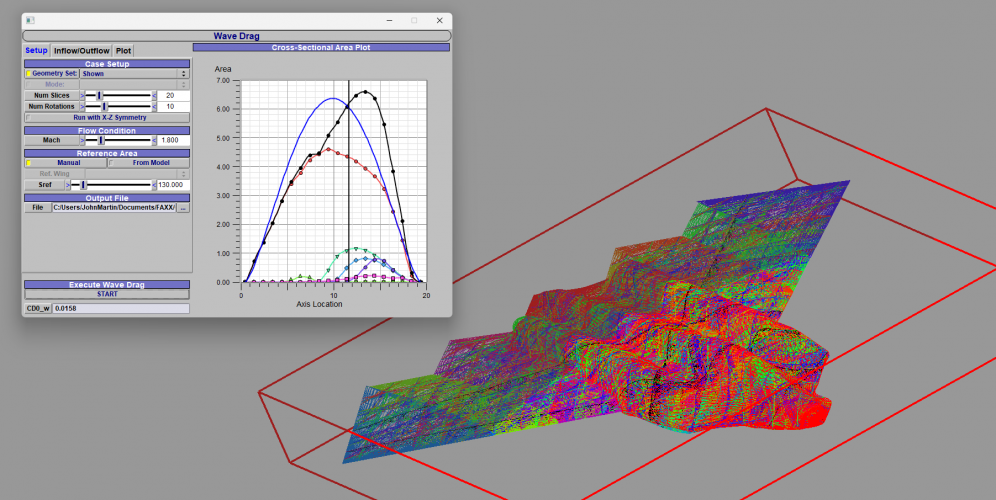
D) I was mindful of wave drag and wanted another lever that could be used to smooth the area profile down the aircraft. It's not obvious and possibly I've note even presented quite the right model but when I did wave drag contouring using OpenVSP* I kind of sculpted out that section to transition into the boat tail. It helped so having it larger further up the aircraft was handy and did provide volume that otherwise might have been lacking if additional systems were actually packaged.

*I made a comment in post 141 about Openvsp for wave drag calculation. I will say it was very easy and addictive to use. It requires you import your model into Openvsp which I used STL for. Then I had to recreate all my sections using the fuselage profile and wing editors (not so hillarious as it crashed a few times before I relearnt save discipline(!)). Then you use the wave drag tool and here's where I learnt something completely new and not openly discussed in the usual books. To calculate wave drag the model is cut up into slices but here's the thing - the slice angle relates to the mach number for which the area distribution impact on the shocks is being calculated. So normal sections as many of us would expect to calculate the whitcomb style area distribution and try coke-bottling etc are specific for the wave drag estimate for Mach=1, but the sectioning cuts are inclined for higher speeds. This means the wave drag estimate will change depending on speed and an ideal distribution of "fat here, skinny there" will be different for different Mach numbers. So I did look at adjusting how fat the dorsal area and the transition into the dorsal gulley were and found that I actually was better off keeping it fuller for longer down the fuselage. Of course the real dudes and duddettes will have supersonic CFD and wind tunnel data and will appreciate the real details and I don't but I watched an excellent OpenVSP video on this tool function and whatever the rights and wrongs of this, that's what the tool developer appeared to explain the calculation approach does. I went for Mach 1.8 and achieved a minimum CDo of 0.015 (edit, make that 0.016) which from what I could gather from reports is not bad, not amazing but at least decent. The area distribution is not bad, a lot better than some other actual wave profile distributions I've seen (not referring to any of yours I should add). That video has interesting explanation about the Sears-Haack body, which was all basically new to me in details.

1779310206760.png

For the inlets I'd like to get some time to go back to the model but I'm pretty busy the next few weeks, hopefully I can return to this in July, as it feels like unfinished business.

On the structural side there might be an argument as touched on by Seragina that the fuselage frames around the engines are not like the really solid frames around the intake ducting. From what I've seen on F-35 structural diagrams it's not obvious there are big frames further back and on the F-14 and F-22 at least it's apparent the nacelles have very marginal structural responsibility. This might be a clear advantage of pushing the engines back more in that the ducting is a (mostly) fixed in place element, can be removed possibly piecemeal and the sizing is diffusing towards the engine. The wing loads around 25% chord where I imagine the highest lift forces being fed into the airframe can then be handled by the thicker frames. On the F-22 I think the frames are really beefy around the ducting but much lighter built around the engine. I did get this (the F-22 cross sections) from looking at someone else's detailed modelling work and it may not reflect actual reality but if you can estimate duct size and external skin dimensions than a potential cross section does look strong around the area metres before the compressor face.

I think with this design the engine being far forward is more challenging as it is up around half way along the weapons bay and as I said to Seragina this does provide opportunity to have a big, even the heaviest frame section there but probably I should sweep the outer mold line a little more generously there over the engine hoops to address VTOLicious's point. I don't think it matters so much if the further back sections are lighter structured and I suspect you and he might agree as further back down the wing the loads will be lower and even it will mainly be a trade between structural efficiency/mass (the classic bd^3/12 beam equation) for making a deeper section vs a thicker section. A lot of the loads will be in the skins but the weapons box does provide a very solid way to pin the engine, bomb and fuel loads together (as well as receiving the undercarriage shock loads).

I think all of what you guys have said is true because these points came up on your designs too even if you had addressed them in different ways or decided to rank them more several and I agree as far as I can.

Lastly the volume is about 88m^3 at last check (I did make a full solid and think this is about right. The wing planform is quite efficient providing a lot of internal volume and wing area without hurting the fineness ratio too much).

All the best,

John
 
Last edited:
Thanks for the details.
1) The structure over the engines is pretty thin agreed. It could probably due with being more humped over the engines as the cost of frontal area.
2) Getting enough air intake area is tied to the overall frontal area so bigger and steeper sides also ends up meaning probably bigger cross section and higher wave drag *note on this below.
Moving the engines a bit back could solve both issues but there's more to this so don't be rash. See below.
3) The side flanks were kind of a concept of driven by multiple factors -
A) I didn't know much about undercarriage kinematics when I started (tip for those who care, brilliant YouTube videos on undercarriage mechanics available from LePhan
This gonna plag you as much as it does me without exact calculation and designing it for real.
This problem is tied to CG (your engines play a bit role here), to wheel base, nose wheel rotation/arm, ground clearance and for an aircraft take-off and landing angle.
The navy requires a larger than is typical land base aircraft clearance angle of ~15° rather than 10°. The angle is the key requirement you can't just ignore.
) but became clear that F-14 style would work very well (I think this is very similar on F-35 too) and I thought maybe the gear would be more tucked in the corner rather than up in the wing. I actually made some different models and tried the F-22 gear design which is probably lighter but has far less stroke and ground clearance. The F-14 as you probably know moves up into the wing roots in quite a neat arc and misses the side bays all together., quite neat.
Note: the main gear is visible in post 141 in case you didn't see this earlier.
It's generally referred to by many as Grumman type gear. A6/F14 are similar here. Mine is a derivative that requires more rotation. Originally, I too wanted it to be similarly stored in the wing like the F22 but my wingbay forced my hand. In any case, as seen in drawings I situated both with the wing structure in mind. The wheel housing partially, served as torsion box same as the front part of the wing area. I left more than half of the upper half of the wingstructure untouched. This should work or yours, too.
B) I wanted to preserve space for additional fuel cells and certainly avionics/arrays but again not clear at that stage.
C) I wanted efficient structure load paths into the sides of the IWB as I tried to conceive of this as being more like a massive tripple beam /torsion box and keel than just a hole (given all the quite sensible arguments about cutting holes in an aircraft.)
If you may remember the F22 has a titanium beam as the centerpiece. This design likely will come up again.
D) I was mindful of wave drag and wanted another lever that could be used to smooth the area profile down the aircraft. It's not obvious and possibly I've note even presented quite the right model but when I did wave drag contouring using OpenVSP* I kind of sculpted out that section to transition into the boat tail. It helped so having it larger further up the aircraft was handy and did provide volume that otherwise might have been lacking if additional systems were actually packaged.
*I made a comment in post 141 about Openvsp for wave drag calculation. I will say it was very easy and addictive to use. It requires you import your model into Openvsp which I used STL for. Then I had to recreate all my sections using the fuselage profile and wing editors (not so hillarious as it crashed a few times before I relearnt save discipline(!)).
yeah, having to recreate everything is what held me back from using it.
Then you use the wave drag tool and here's where I learnt something completely new and not openly discussed in the usual books. To calculate wave drag the model is cut up into slices but here's the thing - the slice angle relates to the mach number for which the area distribution impact on the shocks is being calculated. So normal sections as many of us would expect to calculate the whitcomb style area distribution and try coke-bottling etc are specific for the wave drag estimate for Mach=1, but the sectioning cuts are inclined for higher speeds.
It's not a secret rather people copy and repeat stuff wihout actually bothering to check or knowing etc. This is true for 95% of specialized books. The trick I keep in mind is to non-perpendicular angles to the desired mach angle for shaping. The wings are the easiest part in this respect.
Of course the real dudes and duddettes will have supersonic CFD and wind tunnel data and will appreciate the real details and I don't but I watched an excellent OpenVSP video on this tool function and whatever the rights and wrongs of this, that's what the tool developer appeared to explain the calculation approach does. I went for Mach 1.8 and achieved a minimum CDo of 0.015 (edit, make that 0.016) which from what I could gather from reports is not bad, not amazing but at least decent. The area distribution is not bad, a lot better than some other actual wave profile distributions I've seen (not referring to any of yours I should add). That video has interesting explanation about the Sears-Haack body, which was all basically new to me in details.
Good job to get this number.
Von-Karman-Ogive: minimum wave drag
LV-Haack: maximized volume low drag body
TangentBody: max volume
all tied to L/D finess ratio; I had them as light blue lines in my older F47 drawings. Mainly for the lower half of the fuselage where I needed them for fitting the IWBs.
For the inlets I'd like to get some time to go back to the model but I'm pretty busy the next few weeks, hopefully I can return to this in July, as it feels like unfinished business.

On the structural side there might be an argument as touched on by Seragina that the fuselage frames around the engines are not like the really solid frames around the intake ducting. From what I've seen on F-35 structural diagrams it's not obvious there are big frames further back and on the F-14 and F-22 at least it's apparent the nacelles have very marginal structural responsibility. This might be a clear advantage of pushing the engines back more in that the ducting is a (mostly) fixed in place element, can be removed possibly piecemeal and the sizing is diffusing towards the engine. The wing loads around 25% chord where I imagine the highest lift forces being fed into the airframe can then be handled by the thicker frames. On the F-22 I think the frames are really beefy around the ducting but much lighter built around the engine. I did get this (the F-22 cross sections) from looking at someone else's detailed modelling work and it may not reflect actual reality but if you can estimate duct size and external skin dimensions than a potential cross section does look strong around the area metres before the compressor face.
A solution is raising the duct similar to the yF23 as soon as possible after the mouth, moving the engines back, in the space vacated by the engines, move the side wall in for wave drag reduction. You might be able to angle the engines if far enough for freeing more volume...
I think with this design the engine being far forward is more challenging as it is up around half way along the weapons bay and as I said to Seragina this does provide opportunity to have a big, even the heaviest frame section there but probably I should sweep the outer mold line a little more generously there over the engine hoops to address VTOLicious's point.
Yes, it is more challenging. It is not bad per se mind you. There are plenty similar designs with drones, English Electric Lightning, F32 etc.
I think the CG & gears will dictate it for you in the end.
 
I am curious about the wave drag simulation stuff...

When I look at the models that you guys arrived at, I notice that there's a great emphasis put on ensuring things are 'smooth' to minimize wave drag, like for example the cockpit area, where the cockpit's forward incidence is almost perfectly in line with the radome.

1779315104392.png
And now there's a real world example of this in practice:
1779315310467.png
If I understood correctly, you generally want to have the features of your aircraft to be at a shallow as possible angle vs the incoming air to minimize drag, and yet many production aircraft sport features that are arguably less aerodynamic, like for example cockpits that pop out more / are at a significantly different angle than the nose / radome, or wing sweeps that are shallower than one would expect.

I too would think that fighter jets would look more like the FATE designs or the notional ESAV design where everything is as smooth as possible, but in production aircraft you've got J-XDS and F-22 with a LE sweep between 40 - 50, and even the most FATE like design thus far - the J-36 - only has a 52 degree LE sweep. You've got the F-35, F-22 and J-36 with quite bulky cockpits that certainly pop out more from the nose incidence and some very similar undercarriage designs being recycled from 5th gen designs too.

I'm not sure what I'm asking, but when working on these designs, does it just depend on what stats / features you are looking to optimize and that explains away the differences in these features?

It's for this reason that I wonder if you really need large wing areas and a canard on a carrier-borne aircraft when the fuselage itself is already a major lifting body thanks to the planform. It could help push towards a more conventionally shaped fuselage as well. Sure - it could be marginally more draggy, but otherwise, I'm not sure why real life fighter jets don't all just even more nice, streamlined and smooth.

- you can tell I'm not an engineer from my very non-technical explanations lol
 

Attachments

  • J-36-Fighter-from-X.jpg
    J-36-Fighter-from-X.jpg
    58.2 KB · Views: 40
I'm not an engineer by trade so beyond taking people's word, my only other guiding thought is - if it needs to work right, it has to look right first lol

With that said, I do agree with @VTOLicious. On the YF-23 EMD drawings that VTOL posted, I believe at one point I realized the F-22's bulkhead rings that wrap around the engine nacelles may even be a bit thicker than what is specified on the YF-23 drawings (and you still have to count in aircraft skin. I had a cursory search of the F-35 nacelle bulkhead rings but didn't find much to go off of. On the other hand, the F-22's appear to be on the thicker side especially toward the intake bulkhead. So while the tail where the augmentor / afterburner would go could have a little less clearance, the forward part of the engine would usually get thicker bulkheads.


View attachment 812840
As you can see in the photo below, there appears to be quite a bit more thickness going on especially on top of the engine / nacelle.
View attachment 812839
I think the stealth shaping on the bottom and side walls of the aircraft (beneath the chine) could perhaps be a bit more steep. I can't explain why because I'm not engineer, but it seems to be that every stealth fighter that's been designed has a steeper undercarriage wall whether it's chined or rounded out. Even in the same design family as the YF-23 and Su-57, the undercarriage has steeper walls. The B-21 is the only exception that has a flat and gently tapering undercarriage. I believe this could be better for stealth and it could, in theory, decrease the wetted area and make the aircraft less draggy. Incidentally, having a more steep under carriage could be a boon for your side weapon bays + whatever side arrays you'd be thinking of, as well as creating more room for your engine nacelles.

View attachment 812842View attachment 812843

I've always thought of the undercarriage + tail end of the plane in two configurations. You could go the YF-23 route and simply start tapering real early (usually my go to for trough style exhausts), or you could go with the F-22, F-35, and any of the Chinese 5th and 6th gen fighters and end more conventionally. Generally, option A can actually offer you less weapon bay room due to the taper starting very early. Instead, given the layout of your weapon bays, option B with a more conventional exhaust system + a Su-57 weapon bay layout could net you the most in terms of your weapon bay layout. I'm guessing that's what you were going for as well.

On the subject of weapon bays, weapon bays aren't always uniform in height. The F-22, J20 and F-35 weapon bays have differing depths varying along the length of the bay. So you could possibly get away with a shallower tail bay as you move to end the taper on the aircraft. You also have to keep in mind that you have to leave room for a larger tailhook, which, in turn, has it's own mechanical parts that may take away from bay size, shape etc.

Another thing to watch out for is the diameter of your wheels, how the wheel arm folds, and whether the alotted place and gear doors support the mechanism you want them to fold in. From what I can tell, it looks good though.

For canard, wing and planform related stuff, from what cursory readings I've done, usually carrier borne aircraft have larger wing areas with less sweep or they can have higher sweep and smaller wing area + canards. So you could probably hash it out either way with this in case your volume, aspect ratio or something balloons too much.

Lastly, like VTOL pointed out on the other thread, It's useful to evaluate your model's volume and keep an eye on that as you keep working on it.
This is just speculation, but imo the thicker bracing has to to with TVC. The engine in a non-TVC aircraft pushes almost exclusively forward, and the bracing structure has to carry the load forwards, while I'm pretty sure when you point the thrust off-axis, you can get all sorts of weird loads.
 
When I look at the models that you guys arrived at, I notice that there's a great emphasis put on ensuring things are 'smooth' to minimize wave drag, like for example the cockpit area, where the cockpit's forward incidence is almost perfectly in line with the radome.

If I understood correctly, you generally want to have the features of your aircraft to be at a shallow as possible angle vs the incoming air to minimize drag, and yet many production aircraft sport features that are arguably less aerodynamic, like for example cockpits that pop out more / are at a significantly different angle than the nose / radome, or wing sweeps that are shallower than one would expect.
It's not wave drag per se. It's wave front. Wave drag is more what's come after.
Aligning has limited use to a certain extend or rather distance from the initial point. On one hand you want what comes after like the canopy to stay in the wind shadow for less drag while able to "raise" it above for better view forward. On the other hand you want smooth air flow which requires curving the body => sear-Haack etc. The boundary layer and turbulence interact with the wet surface and effect drag. Minimizing surface is something to strife for, this is most applied to the wing as their volume/surface ratio is worse than the fuselage. Taking advantage of the wind shadow is why you got bumbs place further behind.
I too would think that fighter jets would look more like the FATE designs or the notional ESAV design where everything is as smooth as possible, but in production aircraft you've got J-XDS and F-22 with a LE sweep between 40 - 50, and even the most FATE like design thus far - the J-36 - only has a 52 degree LE sweep. You've got the F-35, F-22 and J-36 with quite bulky cockpits that certainly pop out more from the nose incidence and some very similar undercarriage designs being recycled from 5th gen designs too.
Keep in mind that these are results of evaluating tens of thousands of configurations by supercomputers. We can't do that here so our solution is more driven by experience, some math and best educational guessing.
There are "simple" math ways to get the bearing like I do to get started but that's it. Otherwise I would be stuck for half a year crunching numbers for just one design. And I'm saying that as paper, pen, ruler, compass type of guy here.
I'm not sure what I'm asking, but when working on these designs, does it just depend on what stats / features you are looking to optimize and that explains away the differences in these features?
yes, I mean these are basically concepts at TL3 at best.
It's for this reason that I wonder if you really need large wing areas and a canard on a carrier-borne aircraft when the fuselage itself is already a major lifting body thanks to the planform. It could help push towards a more conventionally shaped fuselage as well. Sure - it could be marginally more draggy, but otherwise, I'm not sure why real life fighter jets don't all just even more nice, streamlined and smooth.
you could try to calculate lift forces for the wings and body and based on that determine the configuration.
For my F/A-XX it would mean I would have to calcuated at least3 different wing foils with different LE/EE angles, too. Look into my eyes and tell me if that's feasible to do by hand here. lol OpenVSP can do that btw. ;)
 
I am curious about the wave drag simulation stuff...

When I look at the models that you guys arrived at, I notice that there's a great emphasis put on ensuring things are 'smooth' to minimize wave drag, like for example the cockpit area, where the cockpit's forward incidence is almost perfectly in line with the radome.

View attachment 812915
And now there's a real world example of this in practice:
View attachment 812916
If I understood correctly, you generally want to have the features of your aircraft to be at a shallow as possible angle vs the incoming air to minimize drag, and yet many production aircraft sport features that are arguably less aerodynamic, like for example cockpits that pop out more / are at a significantly different angle than the nose / radome, or wing sweeps that are shallower than one would expect.

I too would think that fighter jets would look more like the FATE designs or the notional ESAV design where everything is as smooth as possible, but in production aircraft you've got J-XDS and F-22 with a LE sweep between 40 - 50, and even the most FATE like design thus far - the J-36 - only has a 52 degree LE sweep. You've got the F-35, F-22 and J-36 with quite bulky cockpits that certainly pop out more from the nose incidence and some very similar undercarriage designs being recycled from 5th gen designs too.

I'm not sure what I'm asking, but when working on these designs, does it just depend on what stats / features you are looking to optimize and that explains away the differences in these features?

It's for this reason that I wonder if you really need large wing areas and a canard on a carrier-borne aircraft when the fuselage itself is already a major lifting body thanks to the planform. It could help push towards a more conventionally shaped fuselage as well. Sure - it could be marginally more draggy, but otherwise, I'm not sure why real life fighter jets don't all just even more nice, streamlined and smooth.

- you can tell I'm not an engineer from my very non-technical explanations lol
My basic take is that it is not so much just the area but that the second derivative of area, or the rate of change of the rate of change of area needs to be smooth. So everytime the area is increasing suddenly that will induce shocks, and those lead to increased pressures that translate to forces and increased drag. I'm definitely not a supersonics expert! Edit after Seragina's post prompted me: I think it was apparent in the study of optimising the area profile curve in open vsp that there are aspects like having the canopy and dorsal bump that actually help smooth the overall area profile and push some fuselage volume forward, especially as typically the start of the main wing root isn't that far behind. Having a very smoothed in canopy is an approach with some benefits I would expect if the goal is minimum cross section and the aircraft can be longer, (long nose on that J-XDS) but the overall wave drag area profile wants a smooth parabolic profile and a tailored upper fuselage and quite thick chines can help. An aerodynamics channel on YouTube did an analysis of the Typhoon and the author mentioned in his demo of a CFD supersonic flow analysis that the canopy is partly optimised for this aspect. Typhoon, premier aerodynamics. Like I say I'm not a military combat aerodynamicist so it could be balls.

But I also should mention that my recollection of all of this stuff is months old and I am entering my fifties so prone to forgetting bits and pieces. One point I should have said is that while the CD0 number was calculated at a specific Mach number it is known that wave drag does fall with speed. And you could also calculate the wave drag at the transonic regime (ie. At M=1) and it will be quite a lot higher and potentially require some non trivial differences in the design if that was the design goal objective. What I thick I recall is the MDD study with the many different designs where the canard equipped fighter (2407??) with the whale mouth intake under the nose had quite higher wave drag and thus poorer transonic acceleration. So what is OK for the supercruise design point may not be ideal compared to other planforms.

Other point I thought the undercarriages were really complicated but found from LePhans channel that in reality although additional braces and sometimes dampers or additional tie rods can make fighter undercarriages look very complex at least what I've seen is that the Grumman type is used in many aircraft and is mainly dominated as an inclined 45/45 inclined pivot that results in the undercarriage swinging out in an arc and appearing to rotate the wheel as it does so. It's one of those motions that I can't help but be impressed by and yet it is just the result of a simple revolute joint at an offset axis to the main strut. If I am getting you wrong please forgive but seriously it was so surprising to realise that undercarriage designs that impressed me for years like Jaguar, Mirage F1, F-14 and A-6 are really quite brutal compared to the F-111, F-16 etc. The F-22 I would say though does more like tuck up into the fuselage bay. It again looks super impressive cycling, but isn't that complex when seen as a working model!
For your enjoyment and everyone else who hasn't seen these terrific pieces of undercarriage porn...

F-14

F-35

Mirage F1

Jaguar

F-111
 
Last edited:
I'm not an engineer by trade so beyond taking people's word, my only other guiding thought is - if it needs to work right, it has to look right first lol

With that said, I do agree with @VTOLicious. On the YF-23 EMD drawings that VTOL posted, I believe at one point I realized the F-22's bulkhead rings that wrap around the engine nacelles may even be a bit thicker than what is specified on the YF-23 drawings (and you still have to count in aircraft skin. I had a cursory search of the F-35 nacelle bulkhead rings but didn't find much to go off of. On the other hand, the F-22's appear to be on the thicker side especially toward the intake bulkhead. So while the tail where the augmentor / afterburner would go could have a little less clearance, the forward part of the engine would usually get thicker bulkheads.


View attachment 812840
As you can see in the photo below, there appears to be quite a bit more thickness going on especially on top of the engine / nacelle.
View attachment 812839
I think the stealth shaping on the bottom and side walls of the aircraft (beneath the chine) could perhaps be a bit more steep. I can't explain why because I'm not engineer, but it seems to be that every stealth fighter that's been designed has a steeper undercarriage wall whether it's chined or rounded out. Even in the same design family as the YF-23 and Su-57, the undercarriage has steeper walls.

View attachment 812842

Just spend a minute looking at the F-35 photo above in its entirety and then have a look here: https://basicsaboutaerodynamicsandavionics.wordpress.com/2016/03/04/stealth-techniques-and-benefits/
 
I think it was apparent in the study of optimising the area profile curve in open vsp that there are aspects like having the canopy and dorsal bump that actually help smooth the overall area profile and push some fuselage volume forward, especially as typically the start of the main wing root isn't that far behind.
Some cue terms to look up for:
anti-shock body, Whitcomb Body, Küchemann carrot, speed bump
For your enjoyment and everyone else who hasn't seen these terrific pieces of undercarriage porn...
MIG-23 Landing Gear Retraction
 
This is just speculation, but imo the thicker bracing has to to with TVC. The engine in a non-TVC aircraft pushes almost exclusively forward, and the bracing structure has to carry the load forwards, while I'm pretty sure when you point the thrust off-axis, you can get all sorts of weird loads.
It sounds right.

I don't have my old FAR copies anymore courtesy of an asshole stealing my toolbox. :mad:
 
I'm not sure what I'm asking, but when working on these designs, does it just depend on what stats / features you are looking to optimize and that explains away the differences in these features?
The real aircraft are trying to design around more constraints

e.g. for cockpit then you have external field of view (not just over the nose), internal cockpit display layout, access etc. Some of these concepts look like you might as well just go with an embedded cockpit.

Manufacturing is also another item e.g. lots of highly blended thin edges still can carry plenty of load so can be a pain to make

There's also other features e.g. Communications antenna to incorporate with field of view constraints

It's for this reason that I wonder if you really need large wing areas and a canard on a carrier-borne aircraft when the fuselage itself is already a major lifting body thanks to the planform.
The usable lift coefficient is what's important. You need to be able to trim the aircraft at that angle of attack, and have sufficient control power left over to change attitude within an appropriate amount of time.


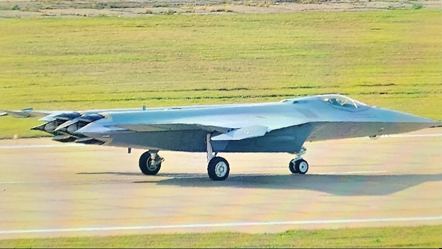
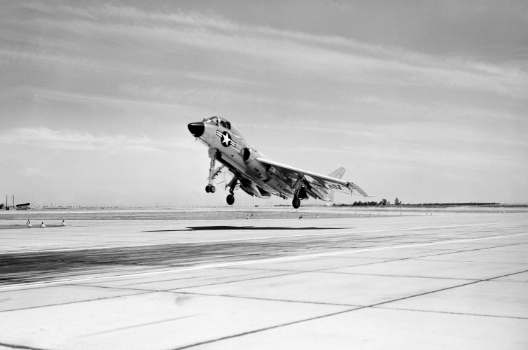
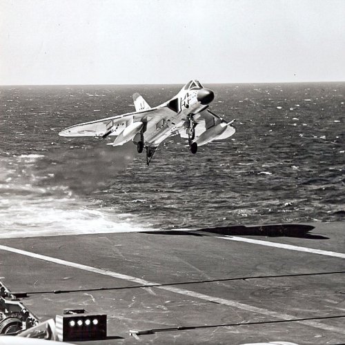
An example of a moderately swept tailless aircraft on landing approach to the carrier. Note the cockpit geometry in particular.

1779340945233.jpeg
 
My basic take is that it is not so much just the area but that the second derivative of area, or the rate of change of the rate of change of area needs to be smooth.
That is my understanding as well. The smoother the rate of change of area the less transsonic drag.


Other point I thought the undercarriages were really complicated but found from LePhans channel that in reality although additional braces and sometimes dampers or additional tie rods can make fighter undercarriages look very complex at least what I've seen is that the Grumman type is used in many aircraft and is mainly dominated as an inclined 45/45 inclined pivot that results in the undercarriage swinging out in an arc and appearing to rotate the wheel as it does so. It's one of those motions that I can't help but be impressed by and yet it is just the result of a simple revolute joint at an offset axis to the main strut. If I am getting you wrong please forgive but seriously it was so surprising to realise that undercarriage designs that impressed me for years like Jaguar, Mirage F1, F-14 and A-6 are really quite brutal compared to the F-111, F-16 etc. The F-22 I would say though does more like tuck up into the fuselage bay. It again looks super impressive cycling, but isn't that complex when seen as a working model!
Yes, an angled axis of rotation/retraction is a very slick way of dealing with apparently-complex retraction problems.

For another fun image, look at the Cessna 210 retractable gear. The gear itself is a simple spring strut, solidly anchored to a hydraulic motor on each side. The retraction moves the entire spring strut a little over 90 degrees to tuck the wheels into the tapering fuselage, but the arc of travel is across a quarter of a sphere. Been a long time since I've swung 210 gear, but IIRC the spring proper does rotate 180deg on the axis of the spring in addition to swinging 90+deg to tuck the wheels into the fuselage.

View: https://youtu.be/pH7N6r1WB6M?si=ykpyppbJTAW6oUHw
 
A lot of consideration goes into this so I can't say much without knowing the detail but I'm certain the difference is
because of wave drag optimisation shaping.
The B21 doesn't have it because it's subsonic while the fighters need it to lower supersonic wave drag.
My own example within my designs:
View attachment 812844
They always had been there I just didn't bother to show them unlike the other minimum drag guidelines.

Can you please share a half-half comparison diagram? Thanks & regards.
 
- you can tell I'm not an engineer from my very non-technical explanations lol
We employ about 60 odd engineers and I hand picked all of them. Almost all have strong academics, degrees and decades of experience, but...

My manufacturing director has worked for 40 years and most of the first 25 was in purchasing, the last 15 in developing strategic purchasing and handling manufacturing capital expenditure.

His classic Columbo phrase is "Of course I'm not an engineer, you guys are far cleverer than me, but could we maybe.....". He will then proceed to gently embarrass all of us as he sees an engineering solution where none of us spotted it. The guy is a natural, mainly because he cares about everything he does and he listens, learns and thinks deeply and has been for a long time. And to be honest that right there is at the crux of what tends to create strong capabilities, it's a craft like any of the other fields folks here excel in.

So for what its worth I wish some of my guys cared as much about the details on their projects as you guys do on this. At the end of the day wanting to be right about stuff is not really the point. It's commitment to honestly finding a successful and sensible way through challenges and that's what we're discussing here even if our hands are somewhat tied behind our backs. The quality of engineering discourse on this site amongst a good bunch of people on this site is genuinly good, but as Seragina notes we could do with employing some committed staff and renting a supercomputer cluster or two if we wanted to go further
 
For those curious about the Super Bug replacement, no future for the WSO in it.
 
I am curious about the wave drag simulation stuff...

When I look at the models that you guys arrived at, I notice that there's a great emphasis put on ensuring things are 'smooth' to minimize wave drag, like for example the cockpit area, where the cockpit's forward incidence is almost perfectly in line with the radome.

View attachment 812915
And now there's a real world example of this in practice:
View attachment 812916
If I understood correctly, you generally want to have the features of your aircraft to be at a shallow as possible angle vs the incoming air to minimize drag, and yet many production aircraft sport features that are arguably less aerodynamic, like for example cockpits that pop out more / are at a significantly different angle than the nose / radome, or wing sweeps that are shallower than one would expect.

I too would think that fighter jets would look more like the FATE designs or the notional ESAV design where everything is as smooth as possible, but in production aircraft you've got J-XDS and F-22 with a LE sweep between 40 - 50, and even the most FATE like design thus far - the J-36 - only has a 52 degree LE sweep. You've got the F-35, F-22 and J-36 with quite bulky cockpits that certainly pop out more from the nose incidence and some very similar undercarriage designs being recycled from 5th gen designs too.

I'm not sure what I'm asking, but when working on these designs, does it just depend on what stats / features you are looking to optimize and that explains away the differences in these features?

It's for this reason that I wonder if you really need large wing areas and a canard on a carrier-borne aircraft when the fuselage itself is already a major lifting body thanks to the planform. It could help push towards a more conventionally shaped fuselage as well. Sure - it could be marginally more draggy, but otherwise, I'm not sure why real life fighter jets don't all just even more nice, streamlined and smooth.

- you can tell I'm not an engineer from my very non-technical explanations lol
Well, the smooth blended design is as much to do with stealth as aerodynamics.

However, canopy design is a long-running compromise. In the 1950s and 1960s visibility took a back seat to drag because it was hard getting to Mach 2 and you needed low drag. The US teen series fighters sacrificed drag for visibility, and could afford it with better engine technology. More recently, technical advances make it possible to consider trading visibility for lower drag again, mostly for supercruise.
 
The real aircraft are trying to design around more constraints

e.g. for cockpit then you have external field of view (not just over the nose), internal cockpit display layout, access etc. Some of these concepts look like you might as well just go with an embedded cockpit.

Manufacturing is also another item e.g. lots of highly blended thin edges still can carry plenty of load so can be a pain to make

There's also other features e.g. Communications antenna to incorporate with field of view constraints


The usable lift coefficient is what's important. You need to be able to trim the aircraft at that angle of attack, and have sufficient control power left over to change attitude within an appropriate amount of time.


An example of a moderately swept tailless aircraft on landing approach to the carrier. Note the cockpit geometry in particular.

View attachment 812939
mauglthwgsxa1.jpg
 

Similar threads

Back
Top Bottom