The obvious solution is to send a large number of high speed and highly manoeuvrable missiles that have just enough destructive power to disable the ships sensors. Once disabled that is when you attack it with the large warheads.
It does assume the ship is not connected into an external sensor network, such as AWACS and satellites, and is flaring her radar at all. SEAD missile can't home on non-working radar, and first you have to provoke the ship to activate it.
It does assume the ship is not connected into an external sensor network, such as AWACS and satellites, and is flaring her radar at all. SEAD missile can't home on non-working radar, and first you have to provoke the ship to activate it.
Yes it can. The missile seeker creates a 3D image of the ship. It can then look up the database of ships and work out exactly where the radar and bridge is located. This tech is 10 years old and is already in service. Multiple missiles can even datalink amongst themselves.
It is near impossible for a ship to intercept an incoming Mach 3 missile that is also jinking at 30g during the terminal phase. Send a dozen missiles at once all data linked together and the ship has no chance.
This is why the medium range air-to-air missile will become the best multirole missile. The AESA seeker can use Synthetic Aperture Radar mode to create 3D images of a ship. It can also passively detect radar emissions for the SEAD role. It is only software and processing power stopping this missile from becoming multirole.
While a multirole weapon is never as good as a dedicated sole purpose weapon it will be much more cheaper overall. A fighter that has 8 missiles providing air-to-air defense if a ship appears it now has 8 anti-ship missiles. If SAM sites turn on it has 8 SEAD missiles. This is extremely versatility and allows fewer weapons to be carried to get the mission done.
It does assume the ship is not connected into an external sensor network, such as AWACS and satellites, and is flaring her radar at all. SEAD missile can't home on non-working radar, and first you have to provoke the ship to activate it.
I'd expect the Aegis ships to be radiating at all times, else someone is going to use other sources to send a load of AShMs addressed "to whom it may concern" and let their terminal seekers sort it out.
Probably, that was the plan for the USN E-2 Hawkeye and F-14 Tomcat/Phoenix missile combo. Hawkeye spots the raid, Tomcat thins out the missiles, AEGIS ships take on what gets through.
The main threat then was Backfires with one or two missiles. I guess ballistic anti-ship missiles are the main concern now. So AEGIS ships are probably the best option for those.
The FA-XX/AIM-260 combo should be ideal for non-ballistic threats.
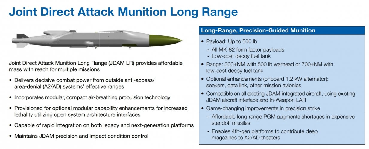
Derived from the company’s widespread guided-bomb kit, the JDAM LR will be able to strike targets or deliver minefields out to 300 nautical miles, effectively converting the Mark 82 warhead into a long-range cruise missile.
Looks like they renamed PJDAM to JDAM-LR...
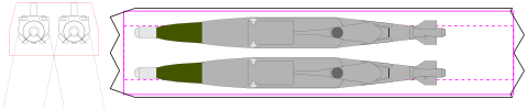
It's slightly bigger than 1000 lb and as long as 2000 lb making it wasteful of IWB volume.
My take:
With an L/D of ~10/1 it's very slick.
Still, even in this case, only one ship in a group would have to do it.
Also, if the ship can track and shoot down AShBMs, it should be able to deal with anti-radiation missile, even a fast one, so it's not a silver bullet, as is suggested above.
Maybe even two micro munition sizes: one that is roughly APKWS sized and an aircraft self defense missile that is closer to the size of a chaff/flare/active decoy expendable. Because APKWS is too big to carry enough to use for self defense.
I see the main benefit of mini-missiles when a short-range offensive capability is needed. For instance to intercept drone swarms without wasting larger/expensive AAMs. But for pure self-defense against missiles, smart decoys (e.g. BriteCloud) are probably sufficient (and certainly cheaper). A good mix of both is probably best to be prepared for all eventualities.
35 seconds into the Sandboxx video this quote is very interesting.
There are two firms left in the running to build this new carrier fighter including Boeing, with what is expected to be a carrier version of their F-47 design.
If you find Sandboxx quoting TWZ and speculating 'very interesting' you might need to consult a dictionary. Once again, Youtube videos can be fun but not a source.
@VTOLicious Have you considered lengthening the nose radome area which might help reduce drag and most of all would align edges with the wing tips so they're all swept at a ~75 degree angle?
Likewise how about aligning the trailing edge with the leading edge on the opposite wing? (That might be easier if you reduce wing sweep from ~45 degrees to 40-42 degrees as on the F-22/F23. You could even go down to 35 degrees wing sweep as on the YF-23 NATF... this would also help with generating more lift).
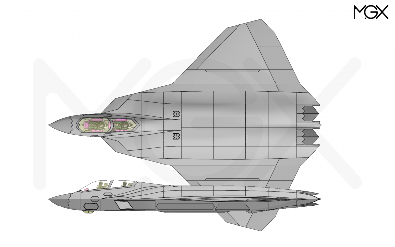
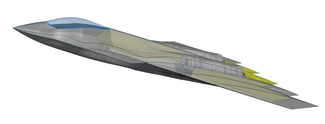
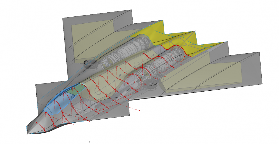
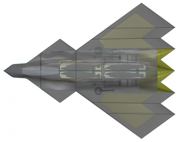
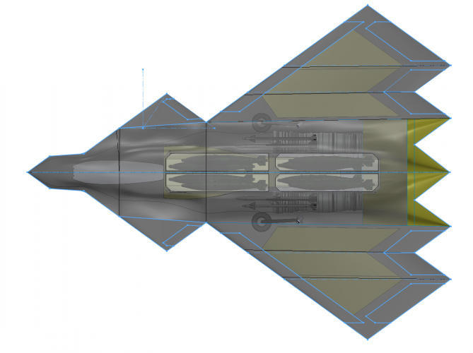
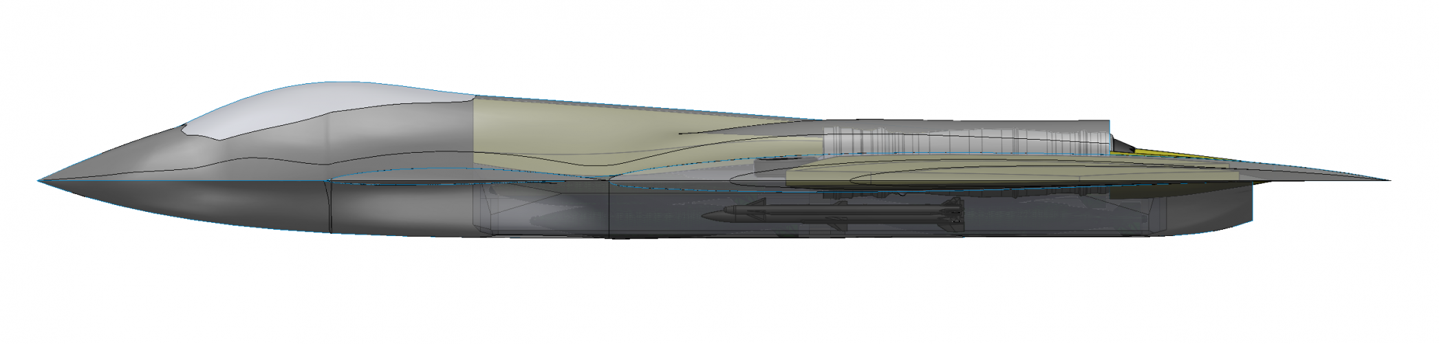
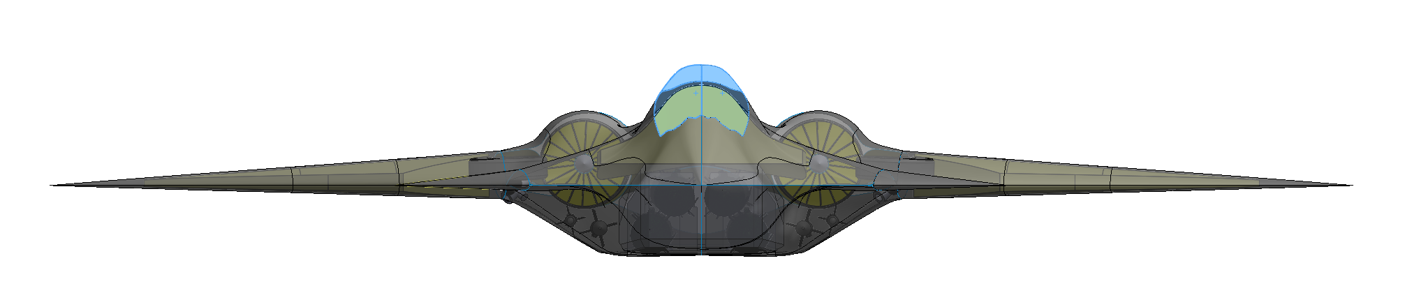
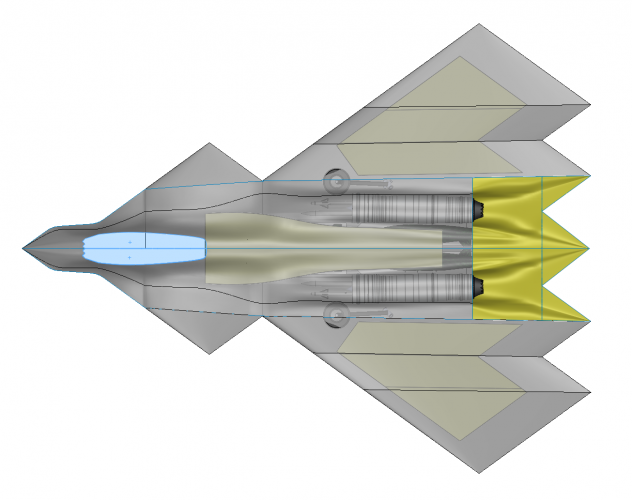
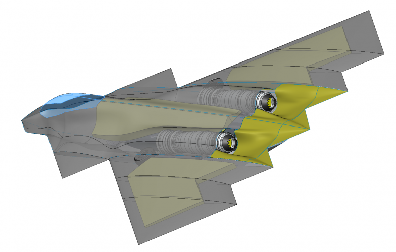
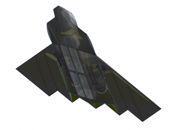
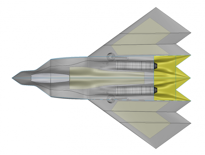
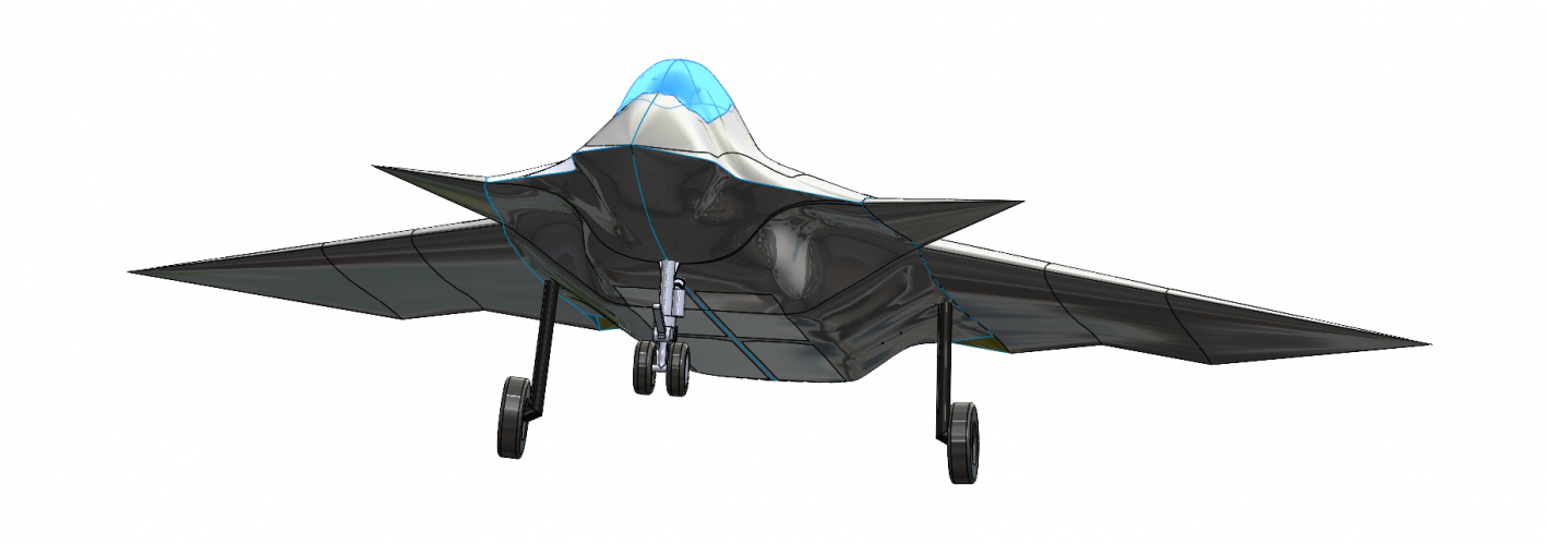
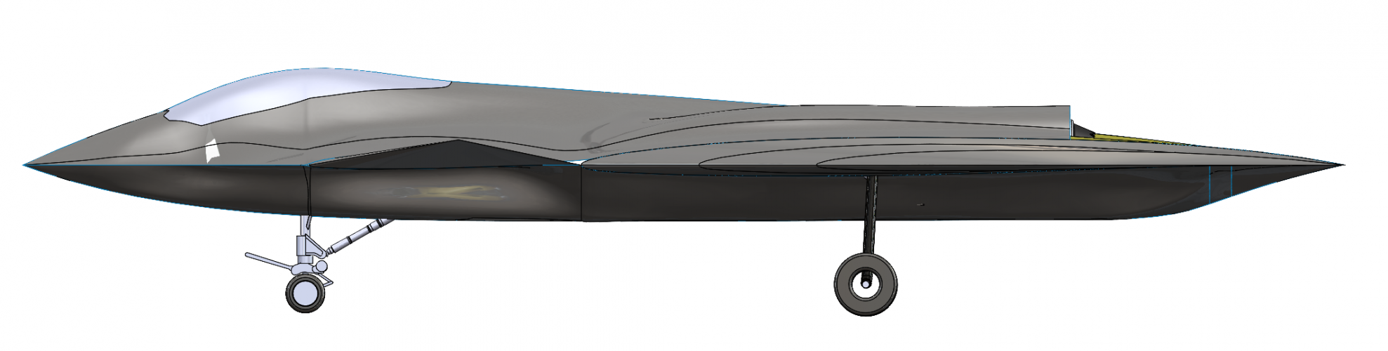
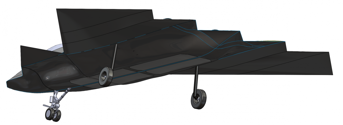
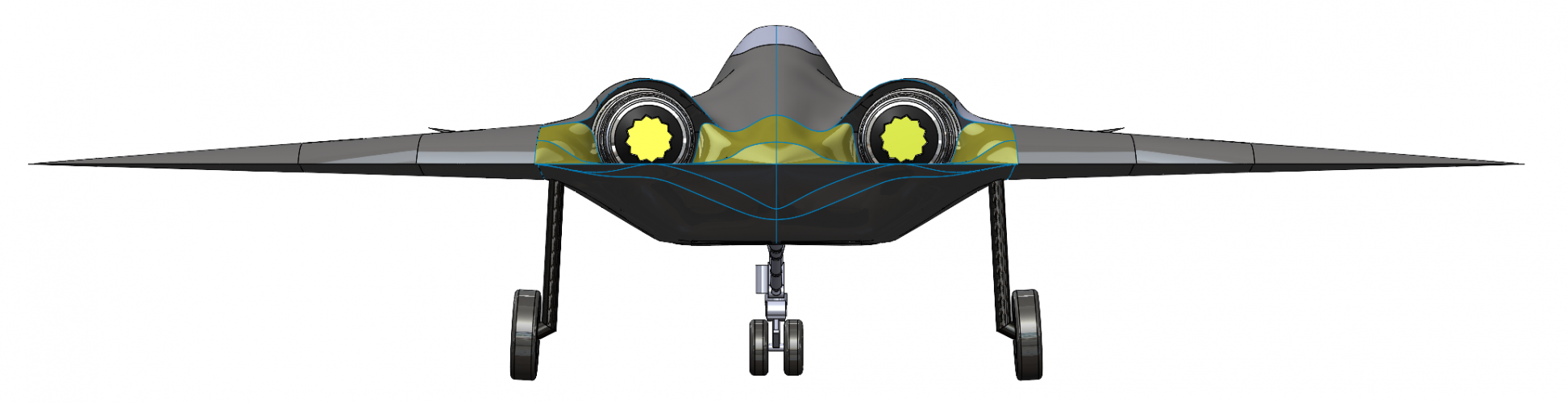
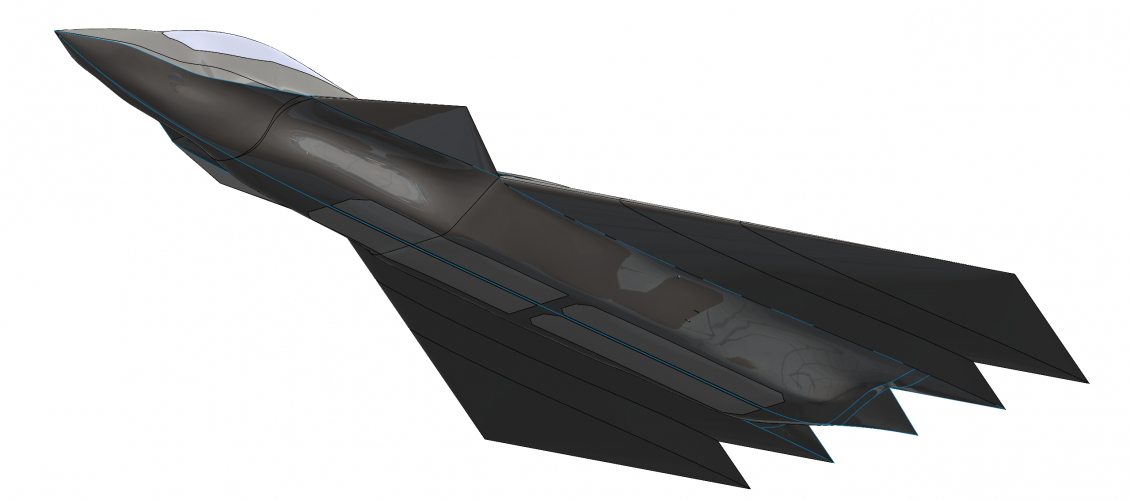
This was my FAXX effort, which was inspired by SK, Reddington777, Rodrigo, Seragina and of course VTOLicious' designs.*
I was very impressed with the promise of the 8x 2000lbs Mk84 capability goal of the A-12 and I know this may annoy some but I found it hard to stop myself at least trying to see what the packaging problems would be.
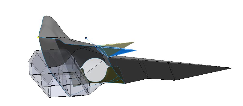
I worked a long while on this but my surfacing skills in Solidworks just aren't up to dealing with the intake interface (or rather I was getting much better after 4 weeks but I have real programs to manage, not sit around designing much as I would wish to). The intake geometry is complex (as usual) but especially as I was trying to evolve a design that could work with a folding Canard that might enable a larger intake throat catchment area in "Canard- / Manouver- and Landing-mode" and an optimised multi-shock intake with increased compressor face shielding in (supersonic "Delta-mode". It got too hard and I had to stop but I am happy to hand out the model if any of the hardcore designers wants it.
Some key attempts at justifying itself....
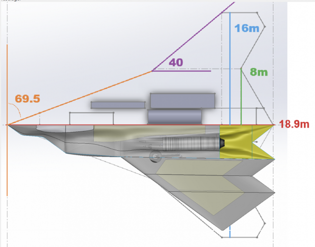
0) Usual dimensions, 18.9m long nose to tail, 15m span
1) Aligned edges on 8 axis (so 'only' 2 main alignment angles, the chine leading into the canard and the main wing leading / trailing edge)
2) Engines (I went with F119 dummy models from rough drawings) positioned as compromise between keeping intake volume managable and still having a trough exhaust.
3) IWB: Engines displaced apart, higher than normal relative to fuselage cross section and slightly toed-in enough to enable a deep IWB cross section to accomodate 50% fuel modules or the so-called beast mode but on internal only (doesn't mean pylons can't be fitted but I would want a lot of delivery payload per sortie in the earliest phases) with carrier a long way back, so I would want maximum range opportunity and then trade for payload keeping RCS characteristics.
3b) Side bays tucked in under the intake ducts and out of the way of the compressor inlet for probably 1 AMRAAM equivilant plus one SRAAM (I used AIM-9X model)
4) Canard but aligned with the main wing and running exactly the same angles, not tilting (forget it), and potentially with a trailing edge flap to augment lift and provide better trim control.
5) Canard has variable geometry but on the root axis, so can angle +20-30deg which enables variable incidence and can be augmented with the trailing flap in a high manourverability mode. Here's the bit you that will spur debate - the Canard can rotate -145deg to tuck in and fair the intakes
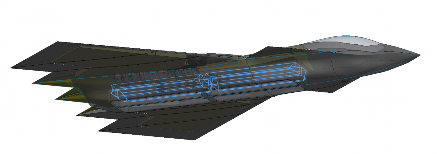
6) The IWB has a thick central keel, much more like a full sectioned beam than F-22 or others. I went for 100mm width and full depth. The bay is therefore split into four quadrants - two forward and two behind. At the mid position the bay has a very thick cross section of 300mm axial to enable a pair of full depth frames in that area.
7) Leading edge flaps on the main wing might be beneficial and full elevons / split dragerons.
8) F-14 type main gear with bays at the wing root and F35 style dual front gear.
9) Wave drag critical mach number about M=1.8. (I area ruled it in OpenVSP using the Wave Drag tool). Max CSA was about 7-8m^2 at approx 62-65% position.
10) Total volume was about 85m^2 (I can check it was a while ago)
11) Tank Volumes - Main dorsal tank 6400L, Wing Tanks 4200L per side (it's a 6% root thickness wing with a 11m root). IWB tanks are roughly 4700L total (see highlighted diagram below) and leave most of the lower bay volume free. In this mode either weapons adaptors are interfaced to the tank, or to the side of the keel and weapon bay structure walls, not saying it's easy but it would be flexible.
12) Main wing area is 62m^2, Canard 6m^2, not including body or to the centreline. Total projection 137m^2 including fuselage.
I appreciate that this is definitely not the likely configuration of the real FAAX but it was a lot of fun for a while playing with ideas, shapes and volumes! Would be nice if someone can magic up the intake geometry but likely it won't be me!
Here's some more views. I would have put some in with the Canard in the dihedral position for landing but Solidworks decided to throw a wobbly(!) and it's 1am at home right now. Off to sleep
PS. As usual if the moderators want to move this, no issue.
* and of course Scott Lowther's research and the many forum threads/posts on this program and it's proginators, plus MDD-Boeing and Northrop's released material.
Nice work! I like it.
Took me a few seconds to get your weird canard setup functionality. Cool use! What's the intake area difference between the modes?
Good wing shaping. Engine exhaust area might need more complex shaping that funnel air for mixing but not really an issue.
I was very impressed with the promise of the 8x 2000lbs Mk84 capability goal of the A-12 and I know this may annoy some but I found it hard to stop myself at least trying to see what the packaging problems would be.
Uhm, my notes from the 5 Billion Dollar Misunderstanding say that the design load was 4x Mk84s or 10x Mk83 or 16x Mk82. Total, not per bay. Bay size of 205" long by 60" wide by 50" deep, and it had two that huge plus side bays for a pair of AMRAAMs.
Not that I'm complaining about you finding a way to fit twice that into a fighter-sized airframe! Just saying you made the job a lot harder than it needed to be.
As to the flapping canards, the biggest issue I see is hiding the hinges from radar.
My critique of the design here is that the lower fuselage should taper up to the end of the exhaust troughs, not end in a vertical line. That gives a solid radar reflection back towards the nose. The whole plane should come to a point at the central dag.
I think the engines would have to be moved back to ensure proper CoG and weight distribution. Or the wing center of lift moved forward, perhaps by reducing wing sweep.
Uhm, my notes from the 5 Billion Dollar Misunderstanding say that the design load was 4x Mk84s or 10x Mk83 or 16x Mk82. Total, not per bay. Bay size of 205" long by 60" wide by 50" deep, and it had two that huge plus side bays for a pair of AMRAAMs.
Not that I'm complaining about you finding a way to fit twice that into a fighter-sized airframe! Just saying you made the job a lot harder than it needed to be.
As to the flapping canards, the biggest issue I see is hiding the hinges from radar.
My critique of the design here is that the lower fuselage should taper up to the end of the exhaust troughs, not end in a vertical line. That gives a solid radar reflection back towards the nose. The whole plane should come to a point at the central dag.
Oops!!! There was a whole set of surfaces missing, I'll fix this shortly and update the pics)
HOW DID I GET THIS SO WRONG!!!! (Obviously by being careless as always in engineering). Very embarrassed to have not bothered to recheck my assumption but I think it came from my goal of an 16,000lb payload target. At least it's not a crazy mass goal compared with the contemporary aircraft. I also wanted to fit 4 JASSM as thats how this all started when some folks here felt very strongly that was impossible.
The canard pivot is clearly a major design challenge, as well as how to achieve this efficiently. The concept I had in mind is that effectively there is a shaped joint root that is 'perfectly' faired at the 0deg and - 148deg positions. I decided that if the canard joint is positioned off these angles then that would imply very hard manoeuvre/high-lift mode and in these conditions that joint not being continuous is probably an acceptable trade given the whole aircraft is either far from the threat zone or angling all over the place anyway (belly at 90 deg to the horizon etc). The area in the Canard mode is intended to be 0.75m^2 per intake (I have made serpentine duct models for this and they are OK but like YF-23 they don't fully block LoS to the compressor (slant view looking diagonally up). I added a significant DSI bump under the canard to reduce this and improve potential pressure recovery in the Canard mode plus produce a smaller throat in the Delta mode. In Delta mode with the Canard folded that DSI plus the 10ish degree root sweep achieves improve blocking of the compressor and a capture area around 0.5m^2. There is an issue that to increase the capture area tradeoff I did consider a significant drooped anhedral tips so that the main face of the canard can stand off the forward fuselage flanks a useful amount but no time to get into modelling this yet/ever. One other 'imagined feature' was to open inward or outward the canard trailing flap in Delta mode to achieve blow in door or bleed door functionality but that's (like all of this) just an idea. I really wanted to ask the engine gurus whether this 2 geometry combined canard-intake had ever been considered.
I think the engines would have to be moved back to ensure proper CoG and weight distribution. Or the wing center of lift moved forward, perhaps by reducing wing sweep.
@VTOLicious Have you considered lengthening the nose radome area which might help reduce drag and most of all would align edges with the wing tips so they're all swept at a ~75 degree angle?
I considered it, but I didn't want to violate my self-imposed length limit, and now I actually prefer the snub nose - It gives me the impression of a rugged attack aircraft
Edit: 15° pilot's field of view over the nose was a self-imposed requirement as well.
Likewise how about aligning the trailing edge with the leading edge on the opposite wing? (That might be easier if you reduce wing sweep from ~45 degrees to 40-42 degrees as on the F-22/F23. You could even go down to 35 degrees wing sweep as on the YF-23 NATF... this would also help with generating more lift).
At the trailing edge, the wing tips and the centre section (incl. engine exhausts) are aligned with the opposite wing. Only the middle part of the trailing edge is not aligned. However, I don't wanna introduce any major changes at this point.
I think the engines would have to be moved back to ensure proper CoG and weight distribution. Or the wing center of lift moved forward, perhaps by reducing wing sweep.
Also, just a comparison between the layout vs. the Northrop double-delta concept study with close-together engines and outboard weapons bays. Arguably wing area behind the engine nozzles can be compared to tail area. But I do take your point.
HOW DID I GET THIS SO WRONG!!!! (Obviously by being careless as always in engineering). Very embarrassed to have not bothered to recheck my assumption but I think it came from my goal of an 16,000lb payload target. At least it's not a crazy mass goal compared with the contemporary aircraft. I also wanted to fit 4 JASSM as thats how this all started when some folks here felt very strongly that was impossible.
That's almost 10t (JASSM-ER) of stuff. Flight to next turn and back.
Like, it's possible to make a carrier strategic bomber, but how much universal character it's going to keep?
That's almost 10t (JASSM-ER) of stuff. Flight to next turn and back.
Like, it's possible to make a carrier strategic bomber, but how much universal character it's going to keep?
Also, just a comparison between the layout vs. the Northrop double-delta concept study with close-together engines and outboard weapons bays. Arguably wing area behind the engine nozzles can be compared to tail area. But I do take your point.
Don't worry too much. CG stuff is complicated and involves a lot of internal system placement. There's way too much variability and we can just say:
the competent engineers will make it work.
That's almost 10t (JASSM-ER) of stuff. Flight to next turn and back.
Like, it's possible to make a carrier strategic bomber, but how much universal character it's going to keep?
Well, when you put in so much empty volume and expect to carry so much more outside, useful....
You're really designing a carrier strategic bomber aircraft(with all other capabilities coming second to this requirement), trying to steal Air Force B-21 lobbying powers.
I am not Navair incarnate, but this probably won't be my first idea. Though... Su-57 is sort of that (via half lighter missiles though), so there are weirdos around.
Well, when you put in so much empty volume and expect to carry so much more outside, useful....
You're really designing a carrier strategic bomber aircraft(with all other capabilities coming second to this requirement), trying to steal Air Force B-21 lobbying powers.
I am not Navair incarnate, but this probably won't be my first idea. Though... Su-57 is sort of that (via half lighter missiles though), so there are weirdos around.
Keep in mind that the rule of thumb of needing 200 shots at a carrier to mission kill it still applies today as it was 50 years ago.
We could do mass attack with all the drones but those need space too. And the more standoff range the larger they are. Just look how big 500 lb JDAM-LR is. It's Mk84 size or the same as JASSM in practice. So either go all out beast mode to get the numbers needed with "few" aircrafts or get more aircrafts with less ordance each or ask the USAF for help.
Keep in mind that the rule of thumb of needing 200 shots at a carrier to mission kill it still applies today as it was 50 years ago.
We could do mass attack with all the drones but those need space too. And the more standoff range the larger they are. Just look how big 500 lb JDAM-LR is. It's Mk84 size or the same as JASSM in practice. So either go all out beast mode to get the numbers needed with "few" aircrafts or get more aircrafts with less ordance each or ask the USAF for help.
I don't think JASSM-ER is in any way related to carriers.
It's a reach extender; reach extension is needed if you want to, say, reach Chengdu from bay of Bengal.
For carrier strike, be it stand off or stand in, you may want to use completely different weapons with different properties, and choose sizes accordingly. That is, either go higher/faster/larger, and limiting yourself to bay size(any bay) will mostly be limiting your booster without adding survivability.
Or you may use your survivability and bring more, smaller munitions, closer.
Nice work! I know from experience that modeling complex geometries of a modern combat aircraft in CAD systems isn't easy, especially if you want to achieve a reasonably realistic and eye pleasing result
Sorry to say that, but I see a few fundamental problems with this design:
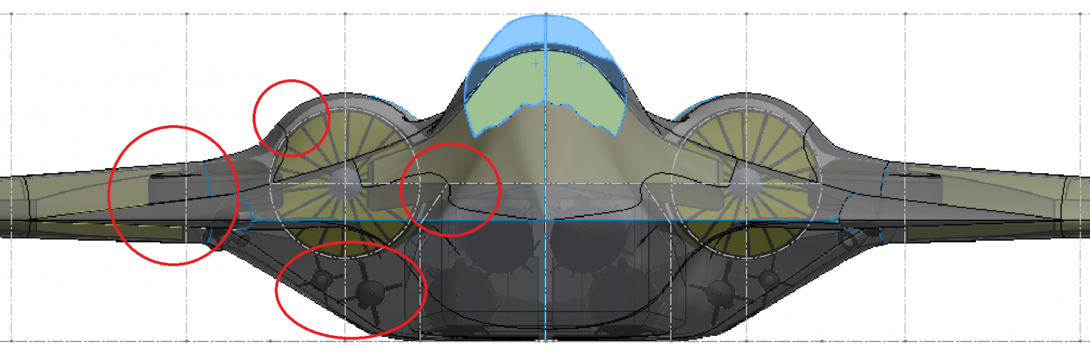
It seems to me that there's too little space around the engines for the load-bearing structure. The lateral clearance to the main weapons bays is also too small - It's important to consider that the engines are serviced and installed/removed from below.
This leads me to the next issue: The AAM bays are positioned very close to and below the engines. And clearance of the depicted weapons to the outer skin is practically non existent - This doesn't seem feasible to me. I also have doubts that there's enough space for s-ducts routed in such a way as to shield the engine face... In conclusion, it's very tight!
...Furthermore, the airfoil thickness seems somewhat excessive for a supersonic fighter.
Keep in mind that the rule of thumb of needing 200 shots at a carrier to mission kill it still applies today as it was 50 years ago.
We could do mass attack with all the drones but those need space too. And the more standoff range the larger they are. Just look how big 500 lb JDAM-LR is. It's Mk84 size or the same as JASSM in practice. So either go all out beast mode to get the numbers needed with "few" aircrafts or get more aircrafts with less ordance each or ask the USAF for help.
I think along the same lines. My standpoint is to optimise the aircraft to carry so much ordnance internally with VLO that the first waves are devastating and the tempo is overwhelming despite the long standoff range. I don't argue that if you could be totally confident in the drone version of this then don't risk pilots but the same benefits for high ingress and egress speed and deep magazine should still stand (in my opinion).
Sorry to say that, but I see a few fundamental problems with this design:
It seems to me that there's too little space around the engines for the load-bearing structure
That's deceptive, I recognised all the arguments about the hoops around the engines and I think the front view makes the section depth look strangely less than it is. For what its worth I think the depth minimum is 100-120mm there. That's an important area for real acting the loads with all the trade offs in frontal area and packaging. It's tight, no question but it wouldn't increase by much if at all in a real design. Unless you are a chief engineer with 20 years experience leading structures teams in which case please educate away!
Ps. I am a 30year qualified engineer who is MD, Technical Director and founder of a manufacturing business in the UK that makes very high performance electric motors / propulsion systems (electronjcs, software, housings, cooling, structures the whole shebang) for Automotive, Aerospace and Motorsport. I realise I'm putting myself up on the parapet here so I didn't want to embarrass myself hence the reticence in sharing this model in the first place I really appreciate the critique but I'm going to squirm and wrestle back, hope you're OK with that
Not mine! From the rear but I was minded that the drive and accessory packs would ideally be accessed from the main and side bays and the empenage trench needs to be removed for retraction. I agree this is different but not necessarily worth dying in a ditch for. In any case are you sure that engines aren't removed by pulling out from the tail (I wasn't so just watched some videos / forced research(!), pretty sure although access to areas of the engine is needed the actual swap is from the tail at least for F-15, F-14 and F-22. Interestingly although no doubt you know this, the F-14 had a track and roller system to support the engine during retraction so no major bodywork was removed. Surprised the F22 accepted needing panels to be disturbed for this task given the VLO criticality and penalties.
This site uses cookies to help personalise content, tailor your experience and to keep you logged in if you register.
By continuing to use this site, you are consenting to our use of cookies.