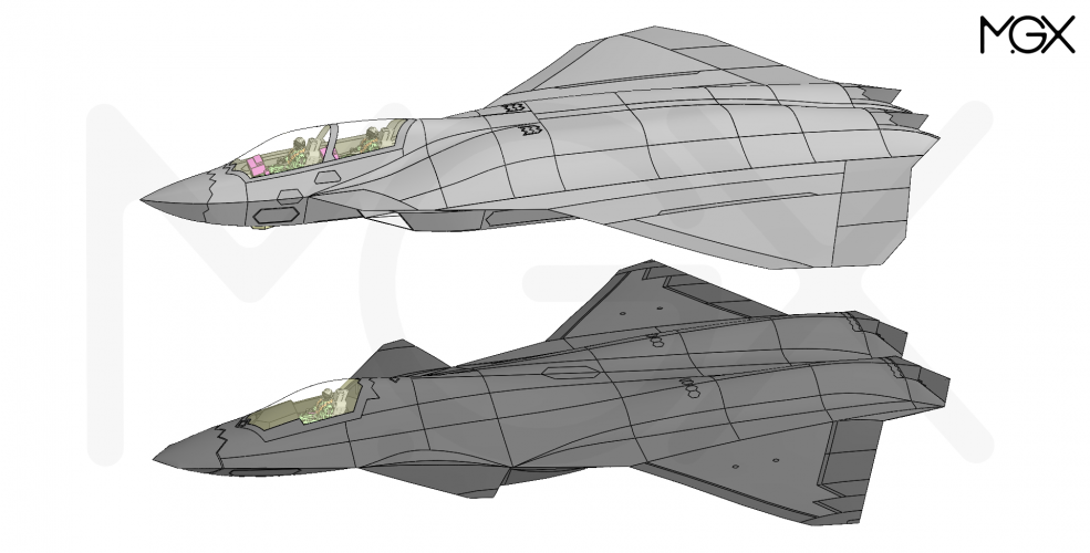
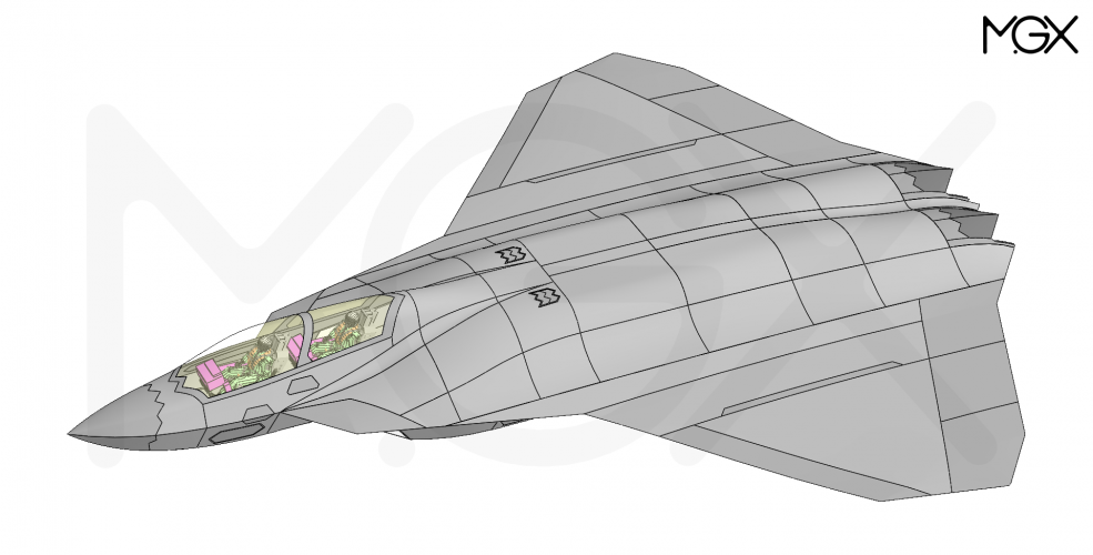
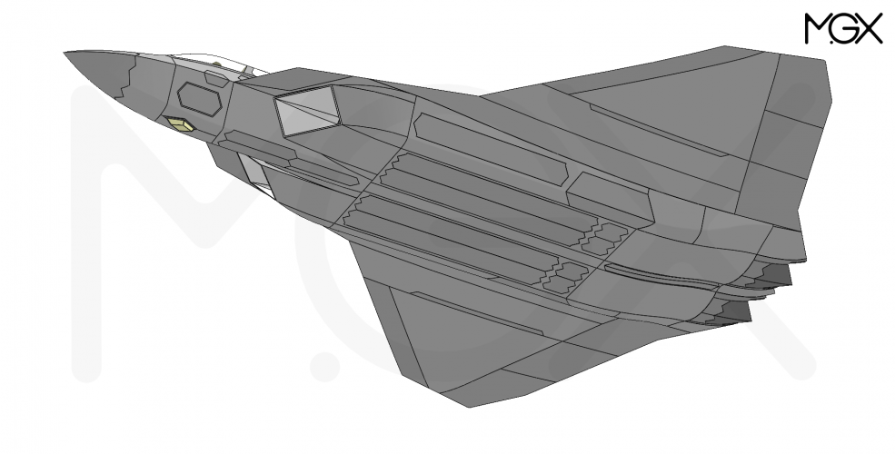
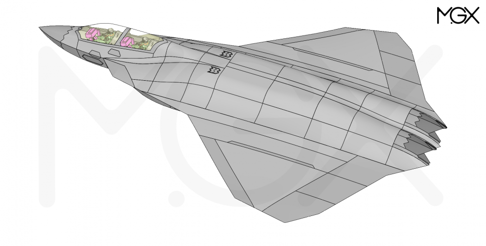
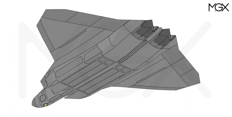
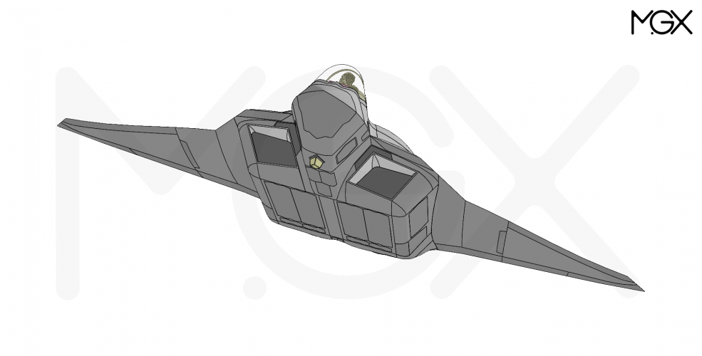
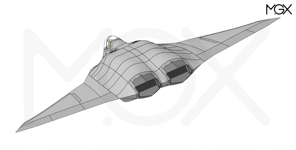
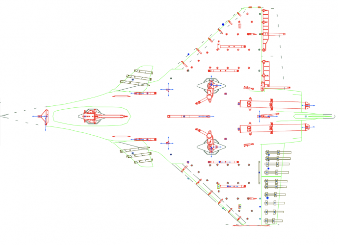
Possible configuration of the Boeing F/A-XX

Regarding AAM loadout, self escort would probably need 4 AAMs, but for the high end war, I don't think there's going to be a whole lot of use cases for self escort. Your AAMs should (in theory) be on your CCAs, which would be flying alongside F/A-XX. However, for worst case scenarios, 2 is an uneasy amount when you've already sacrificed some speed and kinematics.

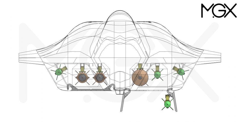
There is still the option of storing AAMs in the A/G-bays. The two A/G-bays are wide enough to accommodate one AMRAAM and one 2000 lb JDAM side by side (or AARGM-ER/SiAW).

It might even be possible to fit two AMRAAMs per bay, if the second AMRAAM is mounted on the door.
E.g. all together two 2000 lb JDAMs + four AMRAAMs and two more AMRAAMs in the side bays. This could be quite useful for some missions... I need to check if that actually fits.
 
Last edited:
Yes, with door rack 2 will definitely fit with ample space left.
If the center rack is moved 2.5-3" to the side and the bay slightly wider a 3rd one could be added. The staggering requires a bit more distance in the length axis, though.

Looking at all the USN's upcoming airbreathing/hypersonic roket motor tests; I have the uneasy feeling they might want to cram in one of those thick boys...
 
Yes, with door rack 2 will definitely fit with ample space left.
If the center rack is moved 2.5-3" to the side and the bay slightly wider a 3rd one could be added. The staggering requires a bit more distance in the length axis, though.

Looking at all the USN's upcoming airbreathing/hypersonic roket motor tests; I have the uneasy feeling they might want to cram in one of those thick boys...
Weapon length is still limited to 15.5ft though. Weapon elevator max.


==============
Back to the tandem bays for a moment:

Can the stress loads go through a keel that the bay is "suspended below"? I know that the catapult loads need to carry through an angle to the keel, but with 2 large weapons per bay you could run a beam down the center of the forward bay without causing interference.

Annoyingly, the ATA bays were huge. About 60" wide, 50" deep and 205" long. (I'm confused by these numbers, but VTOLicious checked that off the published plans so I gotta go with it.)​
60" wide makes sense, 205" long seems a bit long but I can mentally justify it. That depth seems extreme for what we actually need, as no-one uses GBU-8s or whatever has a ~48" box square. I think we can get away with ~25" bay depth.​
My mental model is something like the F-14 (or Su-27) with the space between the engines closed in.
 
Can the stress loads go through a keel that the bay is "suspended below"?
The keel basically becomes a crane(arm) or bridge if you will. The load force, ideally can be broken and redirected away at any angle. The worse angle ofc would be perpendicular to the force direction.
Real world example would be the Sikorsky S-64 Skycrane helicopter.

iu
 
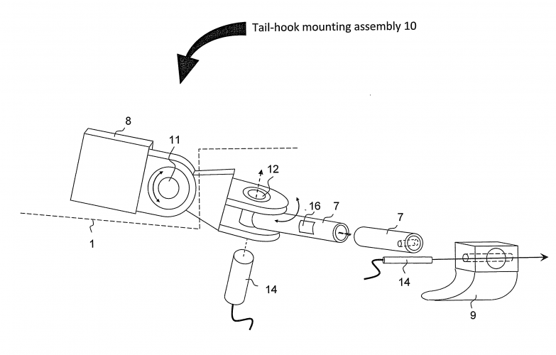
Okay, so the issues for tandem bays would be the Catapult Bar(? don't think that's the right term, I mean the angled beam that carries the catapult load up to the airframe) and the tail hook. Tail hook also has an angled beam attaching it to the keel.

Even assuming a shorter landing gear, the NLG probably needs to be 2m in front of the weapons bay, and the tailhook probably needs to extend 5m aft of the bays. And with 10m worth of bays, now we're talking a plane that is a good 21m long. That's F-111B sized, maybe even A-3 sized (72ft/22m)? But the A-5, which did have 10m worth of bay on the centerline, was actually 23.3m long. So "only" 21m long may actually be too short still!
 
Also, the 2018 Clark report ("Regaining the High Ground at Sea") suggests that most of the CCAs on a carrier will be subsonic ground attack birds, not AAM spear-carriers.

Interesting regarding CCAs. I was thinking that whatever the F/A-XX is going to be, it would complement the F-35C rather than be 'more so'. That suggested something less than a super-Lightning or a navalised F-47 than whatever would have replaced the AYA/A-12 had it ever entered service, or the various Hornets actually in service. That might mean a fast long-range heavy strike and anti-ship aircraft, despite the renders we've seen of naval equivalents of the F-47. CCAs complicate things and the idea of a version of the Stingray being used for strike has been floated, but it's a lightweight in terms of payload and nothing heavier seems to be in the pipeline.

What has to operate off a carrier to do what carriers are supposed to do as part of a fleet? There are only ever going to be three Zumwalts with hypersonic missiles too, which isn't enough, though arming it with those might be a bridge too far. My guess is that it's still something heavy, not an air superiority or fleet defence fighter but a strike, anti-ship, and EW platform. It'll probably look less like a shark and more like a flounder.
 
Last edited:
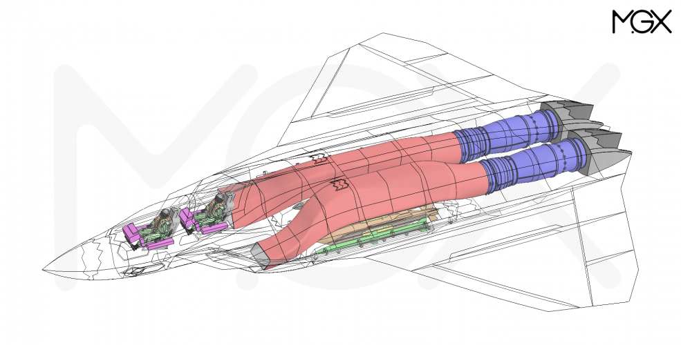
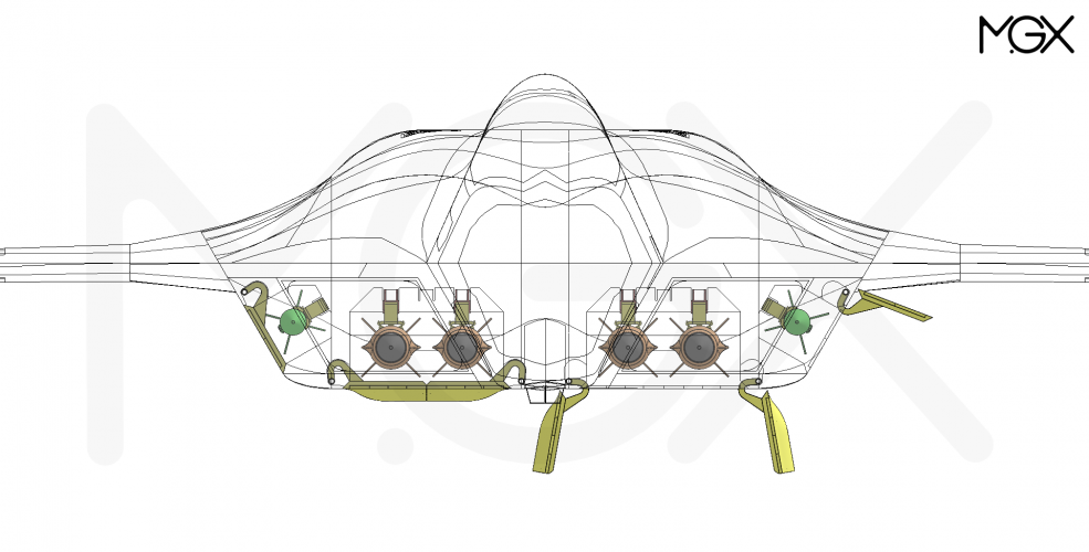
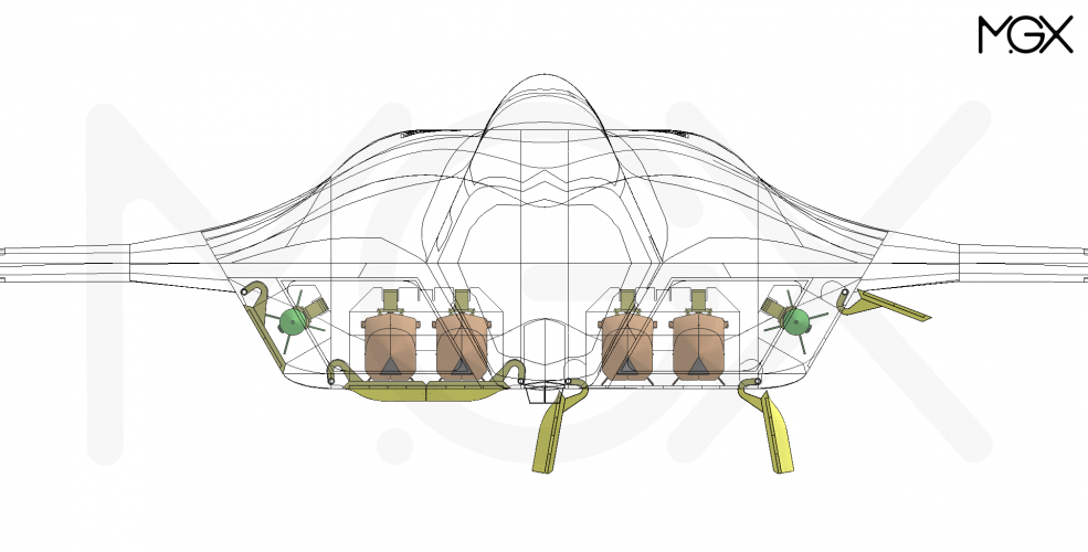
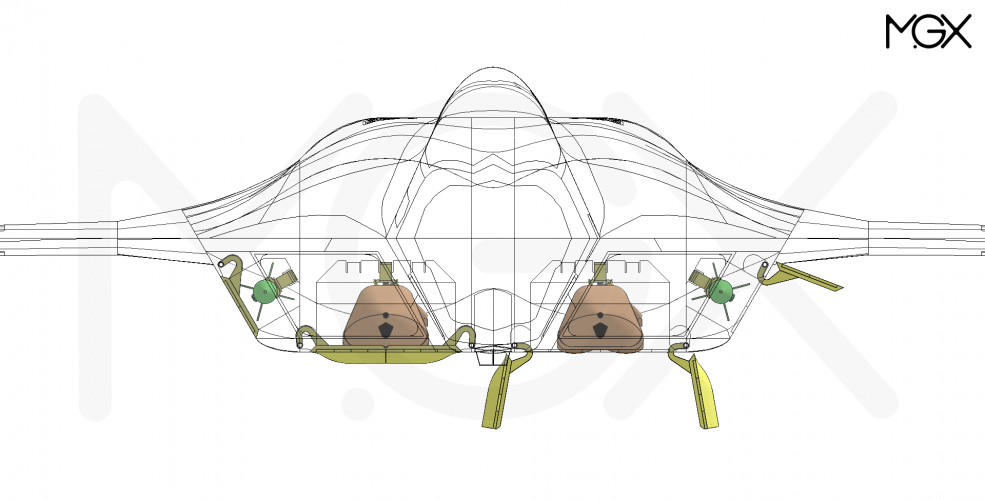
There is still the option of storing AAMs in the A/G-bays. The two A/G-bays are wide enough to accommodate one AMRAAM and one 2000 lb JDAM side by side (or AARGM-ER/SiAW).

It might even be possible to fit two AMRAAMs per bay, if the second AMRAAM is mounted on the door.
E.g. all together two 2000 lb JDAMs + four AMRAAMs and two more AMRAAMs in the side bays. This could be quite useful for some missions... I need to check if that actually fits.

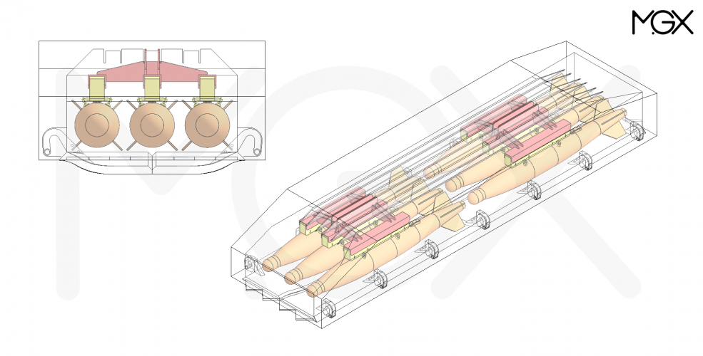
It fits - However, stacking and longitudinal displacement are necessary if four AMRAAMs, or two of them in combination with other weapons, are to be accommodated in a single bay. While this isn't a problem due to the bay's length/depth, it does require careful planning of the positioning.
However, I think that despite the longitudinal displacement, the missiles mounted on the doors should be launched first. Otherwise, the ejection envelope of the missile mounted inside the bay might be too narrow.

MGX FA-XX_IWB+AAM_001.PNG
 
Not quite finished yet, but the basic layout is in place :)

MGX M110, USN strike fighter (notional F/A-XX):
Length: 18.965 m
Wingspan: 14.5 m
Volume: 92 m³

For comparison:

MGX M432, USAF air superiority fighter (notional F-47):
Length: 19.5 m
Wingspan: 14.0 m
Volume: 79 m³

F-22, USAF air superiority fighter:
Length: 18.92 m
Wingspan: 13.56 m
Volume: unknown

MGX FA-XX_028.PNG
 

Attachments

  • MGX FA-XX_020.PNG
    MGX FA-XX_020.PNG
    348 KB · Views: 165
  • MGX FA-XX_021.PNG
    MGX FA-XX_021.PNG
    270 KB · Views: 145
  • MGX FA-XX_023.PNG
    MGX FA-XX_023.PNG
    328.2 KB · Views: 135
  • MGX FA-XX_025.PNG
    MGX FA-XX_025.PNG
    269.7 KB · Views: 136
  • MGX FA-XX_026.PNG
    MGX FA-XX_026.PNG
    215.7 KB · Views: 122
  • MGX FA-XX_027.PNG
    MGX FA-XX_027.PNG
    237 KB · Views: 126
Last edited:
Okay, so the issues for tandem bays would be the Catapult Bar(? don't think that's the right term, I mean the angled beam that carries the catapult load up to the airframe) and the tail hook. Tail hook also has an angled beam attaching it to the keel.

Even assuming a shorter landing gear, the NLG probably needs to be 2m in front of the weapons bay, and the tailhook probably needs to extend 5m aft of the bays. And with 10m worth of bays, now we're talking a plane that is a good 21m long. That's F-111B sized, maybe even A-3 sized (72ft/22m)? But the A-5, which did have 10m worth of bay on the centerline, was actually 23.3m long. So "only" 21m long may actually be too short still!
Most if not all the shock is absorbed by the landing gear (and their added actuator to the nose gear). The bulkhead to which the gears are connected have to be strenghten but otherwise it's not necessearily requiring more bulkheads. The whole airframe needs to be strenghten to deal with its own weight under landing g-force. The bulkhead might feature more nd thicker veins.
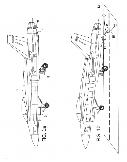
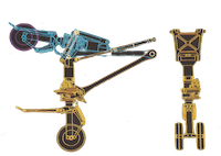
The arresting naval hook/gear on the F18 is rather simple compared to the F16...
US20150247770A1-20150903-D00000.png
So the nose gear needs the extra length for the added actuator in the back and a few inches of structure forward of the hook's hinge.
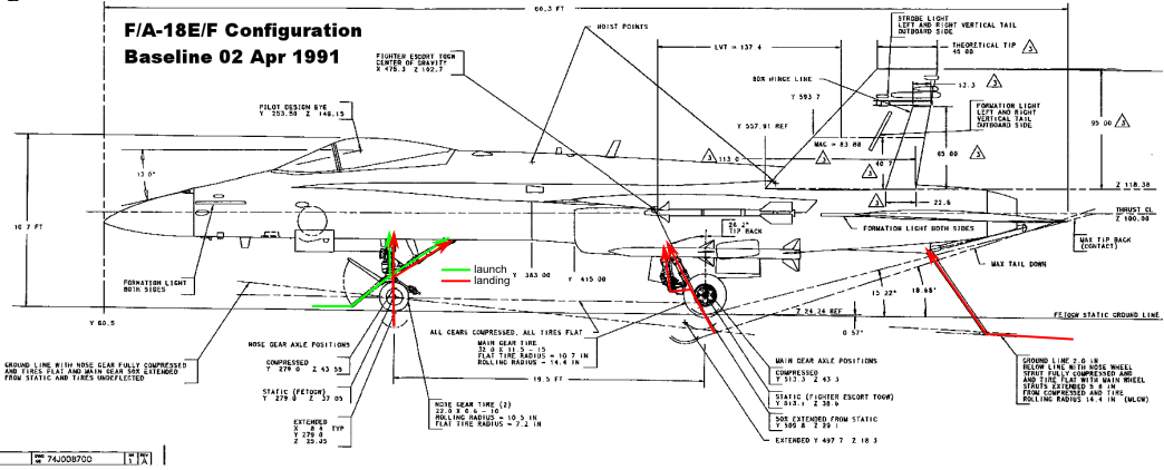
Quick and dirty illustration for the load vectors:

F18-COTOBAR-loads.png
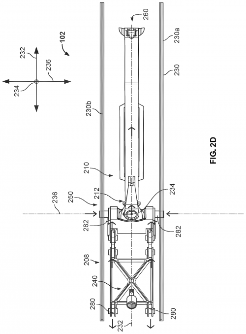
F16's hook for comparison:
US12263941-20250401-D00005.png
 

Attachments

  • US20150247770A1-20150903-D00001.png
    US20150247770A1-20150903-D00001.png
    72.4 KB · Views: 101
It fits - However, stacking and longitudinal displacement are necessary if four AMRAAMs, or two of them in combination with other weapons, are to be accommodated in a single bay. While this isn't a problem due to the bay's length/depth, it does require careful planning of the positioning.
However, I think that despite the longitudinal displacement, the missiles mounted on the doors should be launched first. Otherwise, the ejection envelope of the missile mounted inside the bay might be too narrow.

View attachment 800698
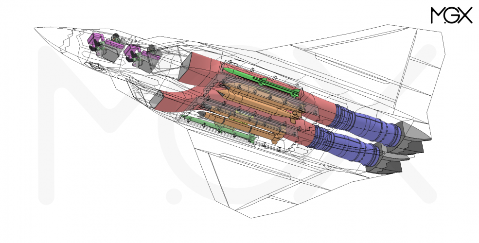
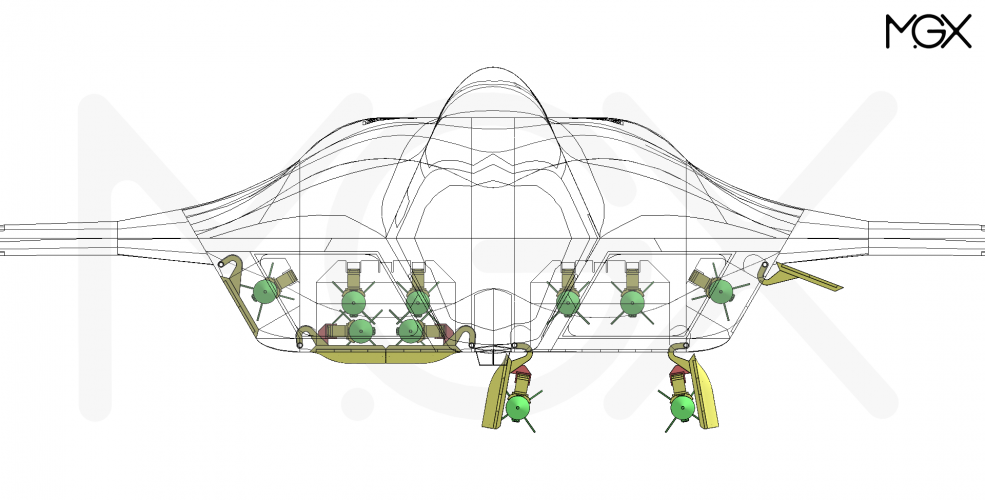
Or loading the main bays with AAMs for a "BARCAP of Doom(tm)". 8x AAMs in the main bay (doors and main mount), plus up to 4x HalfRAAMs in the sides.


Most if not all the shock is absorbed by the landing gear (and their added actuator to the nose gear). The bulkhead to which the gears are connected have to be strenghten but otherwise it's not necessearily requiring more bulkheads. The whole airframe needs to be strenghten to deal with its own weight under landing g-force. The bulkhead might feature more nd thicker veins.
What I mean is that the load lines need to anchor to the keel, not the skin. Catapult angle-bar needs to anchor to the keel, but may be able to intrude a little into the front of a forward bay if necessary. Same applies to the tail hook, if we have to add an angled load path to the keel in the aft end of the aft bay it's fine.
 
What I mean is that the load lines need to anchor to the keel, not the skin. Catapult angle-bar needs to anchor to the keel, but may be able to intrude a little into the front of a forward bay if necessary. Same applies to the tail hook, if we have to add an angled load path to the keel in the aft end of the aft bay it's fine.
It should be doable after all structures do intrude into the bay as part of a setup to atune accustics and regulate vortices. It's the ~1-2.5" layer of structure reserved for the wall "thickness" and door mechanics, too.

Alright, lets take a quick look at landing weight for comparision. I got landing load force data, too, but that requires a bit more analysis.

FA-18E/F is limited to 9000 lb of payload, presumely 2000 lb fuel for a total of about 42-43000 lb => Wing loading: 84-86 lb/sq ft
F35C I'm estimating ~36300 lb => Wing loading: 78.91 lb/sq ft

My F/A-XX with current wing area of ~1100 sq ft (I still want to keep it "small")
landing weight with full 12000 lb internal, 2000 lb fuel, 3000 lb trapped fuel for a total of ~57920 lb
=> Wing loading: 52.65 lb/sq ft
It will be able to land gracefully like a feather :D
 
It will be able to land gracefully like a feather
Wind loading isn't everything though. What you're really interested in is the wing loading * lift coefficient at approach angle of attack. There will be a limit on approach AoA from either pilot view over nose or tailscrape.

The lift coefficient bit really hurts tailless aircraft (and high sweep ones) because they have more restrictions on control power. e.g. high lift devices generate pitching moments that need to be trimmed out through use of controls. e.g. turbulence needs controls to be deflected to remove these inputs. These control deflections impact the air circulation around the wing and reduce lift coefficient. Quite significantly.
 
Wind loading isn't everything though. What you're really interested in is the wing loading * lift coefficient at approach angle of attack. There will be a limit on approach AoA from either pilot view over nose or tailscrape.

The lift coefficient bit really hurts tailless aircraft (and high sweep ones) because they have more restrictions on control power. e.g. high lift devices generate pitching moments that need to be trimmed out through use of controls. e.g. turbulence needs controls to be deflected to remove these inputs. These control deflections impact the air circulation around the wing and reduce lift coefficient. Quite significantly.

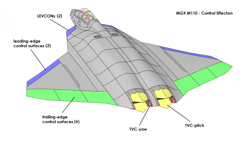
Indeed. That's why I decided to include LEVCONs and TVC in my concept. In total, there are ten individual control surfaces + TVC (pitch/yaw) available to control the aircraft's attitude and lift during landing approach...

Screenshot 2026-02-03 111809.png

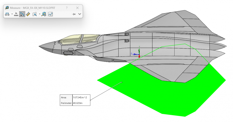
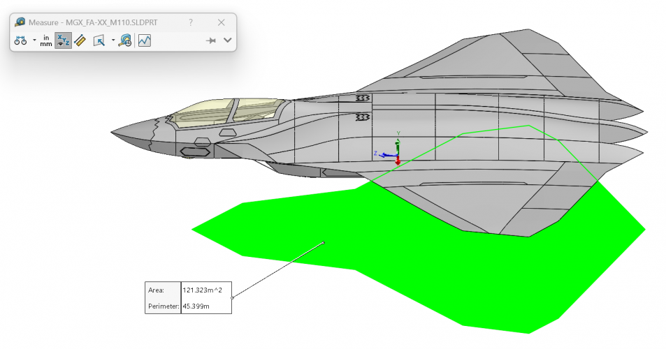
Speaking of wing area. I'm not entirely sure which area I should use as reference area...

A) Wing only: 108 m² (1163 ft²)
Screenshot 2026-02-03 092409.png

B) Wing+LERX: 121 m² (1302 ft²)
Screenshot 2026-02-03 092239.png
 
Last edited:
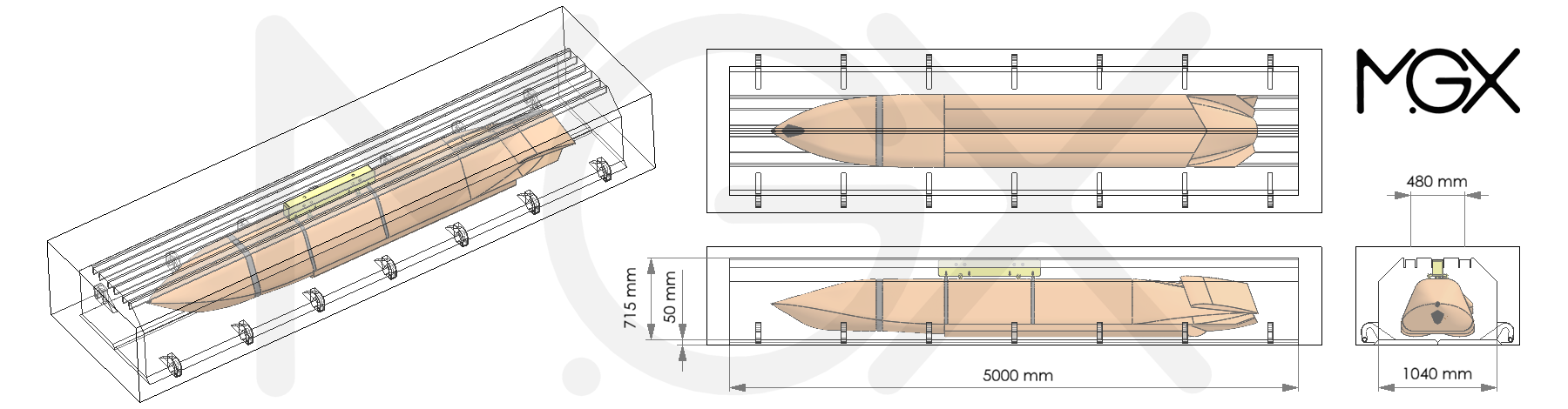
Indeed. That's why I decided to include LEVCONs and TVC in my concept. In total, there are ten individual control surfaces + TVC (pitch/yaw) available to control the aircraft's attitude and lift during landing approach...

View attachment 800813

For rectangular exhaust, it is difficult to design to use yaw & pitch TVC together.
Here, if you fully pitch up/down the yellow flaps, the side red ones for yaw even after moving might fully/mostly be out of exhaust flow. If you can show both the flap sets with full deflection in 3D isometric & 2D side view then it would be clear.
The inboard yaw flaps can't move towards center, the left engine can't yaw right properly, the right engine can't yaw left properly.

> You may have to taper the partition b/w engines &/or increase the separation.
> The regular circular exhausts use overlapped plates. Something similar may have to be used in pitch or yaw flaps here. OR the entire nozzle has to be put on azimuth hinges on top & bottom junction of tail pipe & nozzle.


Speaking of wing area. I'm not entirely sure which area I should use as reference area...

A) Wing only: 108 m² (1163 ft²)
View attachment 800804

B) Wing+LERX: 121 m² (1302 ft²)
View attachment 800805

Why fuselage area also included?
 
For rectangular exhaust, it is difficult to design to use yaw & pitch TVC together.
Here, if you fully pitch up/down the yellow flaps, the side red ones for yaw even after moving might fully/mostly be out of exhaust flow. If you can show both the flap sets with full deflection in 3D isometric & 2D side view then it would be clear.
The inboard yaw flaps can't move towards center, the left engine can't yaw right properly, the right engine can't yaw left properly.
First of all, this is a conceptual design. Hence, it does not go deep into technical detail. However, a general sanity check is indeed part of the exercise. Usually I base my considerations on existing examples.

Having said that, this TVC-nozzle design, with yaw-paddles integrated in the sidewalls, is what is suspected to be part of the yaw-control-system utilized by the Chinese J-50...
SAC J-50_0001.png

Furthermore, yaw control is not intended to be achieved by TVC alone. I also consider "crow-mixing" of the two outboard trailing-edge flaps as feasible means to control yaw, especially at slow speed, e.g. landing approach. The J-50 uses all-moving-wingtips instead.
 
My F/A-XX with current wing area of ~1100 sq ft (I still want to keep it "small")
landing weight with full 12000 lb internal, 2000 lb fuel, 3000 lb trapped fuel for a total of ~57920 lb
=> Wing loading: 52.65 lb/sq ft
It's going to need to land slower than an F-14 for that weight. Something under 140 knots.
 
I'd still expect lift coefficient on approach to be quite low. There's only so much that can be done without big slotted flaps.
The Rafale wing might be a good proxy for F/A-XX (assuming LEVCONs are equally effective as canards in generating lift).

If @VTOLicious can measure the Rafale wing area and calculate the lift coefficient, then apply the same coefficient to his F/A-XX wing area (108m2), that should give some reasonable weights for F/A-XX for both take-off and landing. For example, Rafale's approach speed @ 16 degrees AoA is:
  • 125 knots @ 11t
  • 147.8 knots @ 16.14t
Likewise max TO weight (on land) is 24.5t, so applying the same wing area scaling factor should give a reasonable max take off weight. Max catapult launch weight is 22.2t using a 75m catapult, which scales to ~27t using the standard USN 90m long catapult (+23% longer power stroke). The front landing gear might be the limiting factor here (in terms of max acceptable tow force)... possibly need to take the Rafale landing gear and scale it up a little.
 

Attachments

  • Rafale landing gear 50px=1m.png
    Rafale landing gear 50px=1m.png
    24.3 KB · Views: 123
  • Rafale structural top 100px=1m.png
    Rafale structural top 100px=1m.png
    296.6 KB · Views: 113
Last edited:
It fits - However, stacking and longitudinal displacement are necessary if four AMRAAMs, or two of them in combination with other weapons, are to be accommodated in a single bay. While this isn't a problem due to the bay's length/depth, it does require careful planning of the positioning.
However, I think that despite the longitudinal displacement, the missiles mounted on the doors should be launched first. Otherwise, the ejection envelope of the missile mounted inside the bay might be too narrow.
Can the weapons bay fit 2x SDB-sized bombs and an AMRAAM side by side?

If so you could fit:
- 2x2 SDBs on one side
- 1x AMRAAM on the other side
- 2x more SDBs on the bay door below the SDBs
- 1x AMRAAM on the bay door below the AMRAAM
Giving you a total of 2x AMRAAM + 6x SDBs per bay, or 6x AMRAAMs + 12x SDBs per aircraft... basically the same carriage as 3x Boeing EWPs. (The weapons on the bay doors would be launched first obviously)

Also do you have a target for internal fuel volume / internal fuel fraction? For shorter defensive air combat missions I've been estimating an FF requirement of ~0.35 and for 1,000nm+ strike missions an FF of ~0.4. That might make dorsal CFTs attractive in order to allow for a skinnier cross section (without the CFTs) for supersonic missions. Thoughts?
 
Last edited:
Wind loading isn't everything though. What you're really interested in is the wing loading * lift coefficient at approach angle of attack. There will be a limit on approach AoA from either pilot view over nose or tailscrape.

The lift coefficient bit really hurts tailless aircraft (and high sweep ones) because they have more restrictions on control power. e.g. high lift devices generate pitching moments that need to be trimmed out through use of controls. e.g. turbulence needs controls to be deflected to remove these inputs. These control deflections impact the air circulation around the wing and reduce lift coefficient. Quite significantly.
The standard design requirement for aircrafts regardless whether they are civil or military is 8° for both take-off and landing with up to 15° for obstacles found around airports. Flaps at 20° nominal plus some up to 25° for fringe cases etc.
I'm not so worried because I assume both F47 and F/A-XX most likely will have fluidic control via bypass air vents on wings and fuselage.
The fine control and extra lift this provides should be more than sufficient.

The Rafale wing might be a good proxy for F/A-XX (assuming LEVCONs are equally effective as canards in generating lift).

Rafale's approach speed @ 16 degrees AoA is:
  • 125 knots @ 11t
  • 147.8 knots @ 16.14t
At least for what I've posted of my wing the Rafale has a worse wing. A simple analysis on sweep and aspect ratio gives a difference of ~5.1% and ~5.9% in drag respectiely. Taper ratio requires more complicated area & span calculations to compare them so I'll skip this.
My goal for a better wing raises the difference with a minimum of 8%.
The Rafale's AoA is way too high! The wing loading I get here is
240.7 kg/m^2 ~49.255 lb/sq ft and 353.17 kg/m^2 ~72.27 lb/sq ft

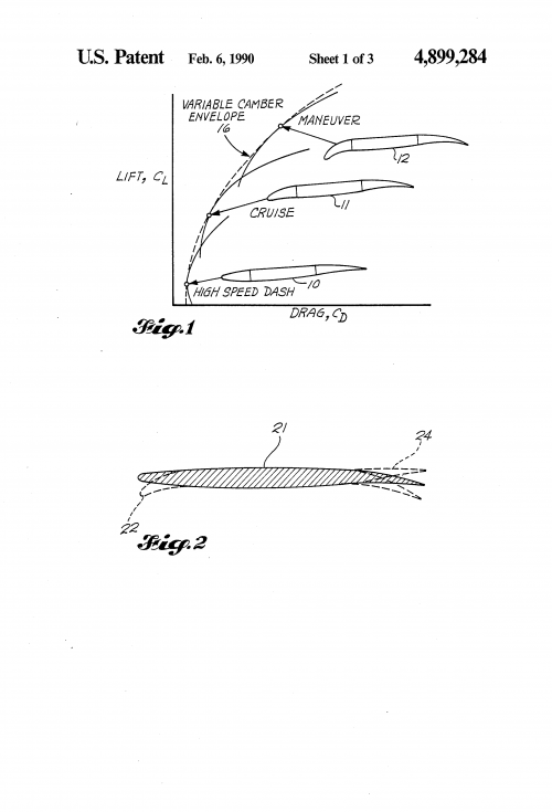
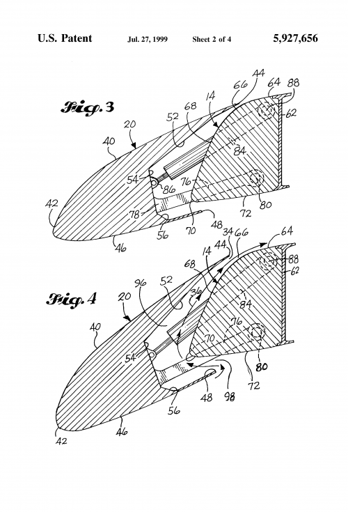
I expect the F/A-XX to use newer wing lifting design based on variable chamber and better stealthy slat used on the X-32:
 

Attachments

  • US4899284-drawings-page-2.png
    US4899284-drawings-page-2.png
    35.1 KB · Views: 103
  • US5927656-drawings-page-3.png
    US5927656-drawings-page-3.png
    99.5 KB · Views: 90
The Rafale wing might be a good proxy for F/A-XX (assuming LEVCONs are equally effective as canards in generating lift).

If @VTOLicious can measure the Rafale wing area and calculate the lift coefficient, then apply the same coefficient to his F/A-XX wing area (108m2), that should give some reasonable weights for F/A-XX for both take-off and landing. For example, Rafale's approach speed @ 16 degrees AoA is:
  • 125 knots @ 11t
  • 147.8 knots @ 16.14t
Likewise max TO weight (on land) is 24.5t, so applying the same wing area scaling factor should give a reasonable max take off weight. Max catapult launch weight is 22.2t using a 75m catapult, which scales to ~27t using the standard USN 90m long catapult (+23% longer power stroke). The front landing gear might be the limiting factor here (in terms of max acceptable tow force)... possibly need to take the Rafale landing gear and scale it up a little.

Interesting thoughts, thx for your input!

But I think a double-delta wing (with LEVONs) has completely different characteristics than a delta wing (with canards). Not to forget internal weapons carriage keeps the wing clean, which enhances lift and eliminates drag from external stores. Therefore, I believe the Rafale would be a poor reference.
Estimating the lift coefficient of a wing is extremely difficult in any case, especially when leading-edge and trailing-edge devices are involved. Hence, I think it's not worth to go that way.

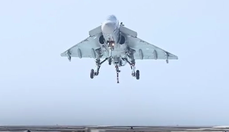
Perhaps the HAL Tejas (naval version) would be a better comparison? :D
Screenshot 2026-02-03 104707.png
 
Can the weapons bay fit 2x SDB-sized bombs and an AMRAAM side by side?
Fore sure!

Also do you have a target for internal fuel volume / internal fuel fraction? For shorter defensive air combat missions I've been estimating an FF requirement of ~0.35 and for 1,000nm+ strike missions an FF of ~0.4.
I think a fuel fraction of around 0.3 would be required for reasonable range.
See also here: https://www.secretprojects.co.uk/th...ion-of-the-boeing-f-47-ngad.45793/post-862848
That might make dorsal CFTs attractive in order to allow for a skinnier cross section (without the CFTs) for supersonic missions. Thoughts?
Haha, I would love to remove that humpback and make the airframe skinnier, but the issue is the engine ducts (in combination with those extra large IWBs). They eat up a lot of internal volume!

Btw, I once started a thread for the discussion of CFTs: https://www.secretprojects.co.uk/th...-for-f-35-and-other-stealth-y-aircraft.46811/
 

Attachments

  • MGX FA-XX_041.PNG
    MGX FA-XX_041.PNG
    359.1 KB · Views: 199
  • MGX FA-XX_042.PNG
    MGX FA-XX_042.PNG
    366.3 KB · Views: 201
Last edited:
I would love to remove that humpback and make the airframe skinnier, but the issue is the engine ducts (in combination with those extra large IWBs). They eat up a lot of internal volume!
Makes me wonder if the F119 engines and 5m long weapon bays are too much for this aircraft.

The alternative would be F414-sized engines with ~80cm fans and ~120kN thrust. And you wouldn’t lose too much by shortening the weapon bays to ~4.4m (-12%)… could still fit a 500lb bomb + 2-3 SDBs in tandem on each side of the bay.
 
Makes me wonder if the F119 engines and 5m long weapon bays are too much for this aircraft.

The alternative would be F414-sized engines with ~80cm fans and ~120kN thrust. And you wouldn’t lose too much by shortening the weapon bays to ~4.4m (-12%)… could still fit a 500lb bomb + 2-3 SDBs in tandem on each side of the bay.

The issue is more the depth than the length of the bays. And the depth is solely due to JASSM.
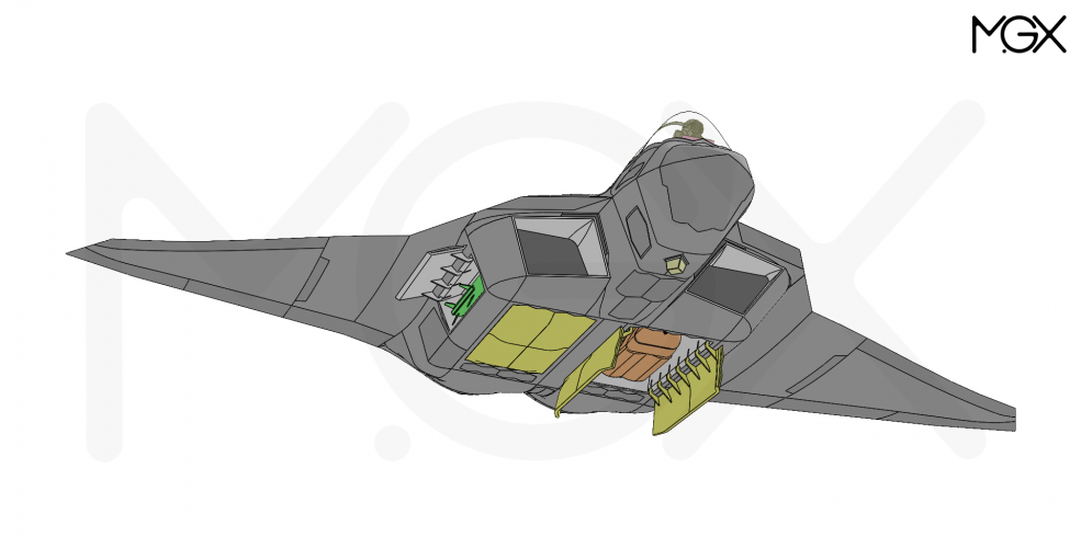
MGX_AG-IWB_03_JASSM.png


I've considered reducing the depth and bulge the doors instead. This would shift the intake ducts downwards, significantly reducing the overall volume.
 
Last edited:
But I think a double-delta wing (with LEVONs) has completely different characteristics than a delta wing (with canards).
Yes it is different.
One asset of Levcons is probably stealth : it is attached to the main wings so more stealthy than a separate and low sized canards I think.
 
The issue more the depth than the length of the bays. And the depth is solely due to JASSM.

I've considered reducing the depth and bulge the doors instead. This would shift the intake ducts downwards, significantly reducing the overall volume.

I modified the IWB doors. In doing so, I noticed that the intake ducts in the middle section had too large a cross-section. I have now redesigned them so that they occupy 87.5% of the area in the middle and taper down to 75% towards the intake. Furthermore, the gap of the boundary layer diverter was excessive and was therefore also slightly reduced...

As a result, the outer mold line is sleeker and airframe volume is reduced by 4.5 m³, to 87.5 m³.

MGX FA-XX_IWB+AAM_003.PNG
 
The issue more the depth than the length of the bays. And the depth is solely due to JASSM.
View attachment 800940


I've considered reducing the depth and bulge the doors instead. This would shift the intake ducts downwards, significantly reducing the overall volume.
Dear VTOLicious,

Is it certain (with an example somewhere) that the dorsal mount adaptor on JASSM couldn't be embedded into your structure? It seems like a significant depth penalty that might be resolvable with some dedicated mechanical hardware set into the roof of the bay. (It it was "my project irl" I think I'd insist on sorting the mounting hardware to get the bay even sleeker, just saying).
 
Dear VTOLicious,

Is it certain (with an example somewhere) that the dorsal mount adaptor on JASSM couldn't be embedded into your structure? It seems like a significant depth penalty that might be resolvable with some dedicated mechanical hardware set into the roof of the bay. (It it was "my project irl" I think I'd insist on sorting the mounting hardware to get the bay even sleeker, just saying).

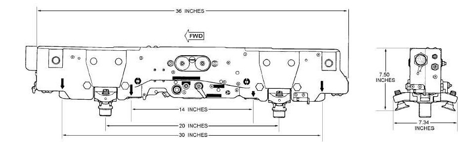
I have taken into account a height of approximately 7.5 inches for the bomb ejector racks. Something like that...
BRU-32-A bomb ejector rack_01.jpg
Those racks need to be accessible for installation, removal, weapons loading, etc. And they must be repositionable to allow versatile weapon loadouts. You cannot fully recess them into the structure.
 
Last edited:
MGX F/A-XX M200, Weapons Bay Loadout Options:
  • Side bays are equipped with 2 AMRAAM as standard (323 kg)

8x AMRAAM - Total payload weight: 1292 kg
AG-IWB_020.PNG

4x AARGM-ER - Total payload weight: 2191 kg
AG-IWB_025.PNG

4x JSOW - Total payload weight: 2311 kg
AG-IWB_024.PNG

2x JASSM - Total payload weight: 2365 kg
AG-IWB_023.PNG

24x SDB II - Total payload weight: 2555 kg
AG-IWB_026.PNG

12x JDAM / 500 lb - Total payload weight: 3359 kg
AG-IWB_021.PNG

4x JDAM / 2000 lb - Total payload weight: 4247 kg
AG-IWB_022.PNG
 
The weapon load is pretty optimistic when you factor in additional real engineering constraints like actuator sizing, real thicknesses, adequate space for loaders, adapters for different mounting locations etc. Which all add up to be a good 10-20% extra in my experience. But it's unrealistic for @VTOLicious to do this by himself.

I'd just bear in mind that a real aircraft designed around this is likely to be quite a bit larger, or carry less.
 
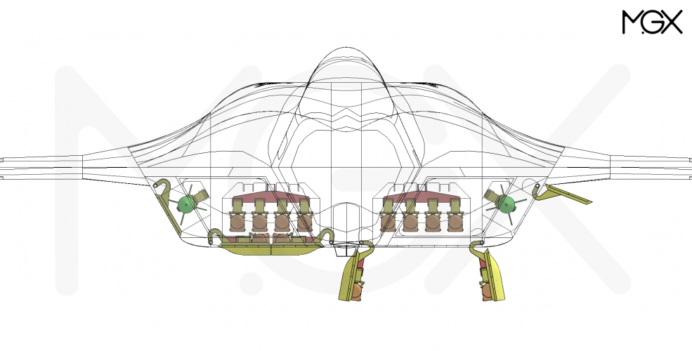
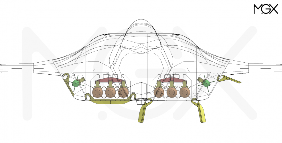
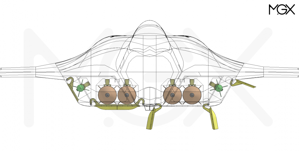
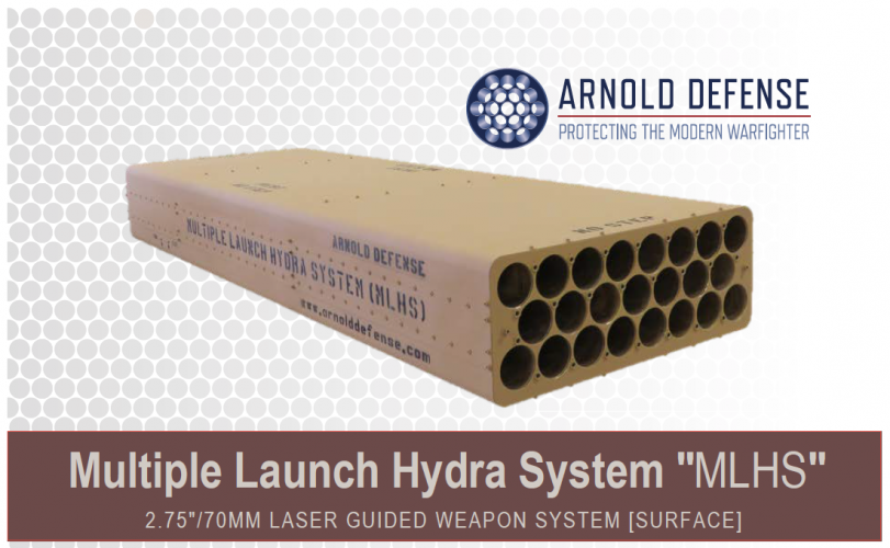
Great work VTOLicious! Very inspiring. I hope the GCAP weapon bays match this. Do you think you could possibly mount 4 round APKWS rocket pods on the bay door mounts?

APKWS might be a good option for drone hunting. Not entirely sure if a F/A-XX is the right platform for this use case.

Anyways, mounting standard launchers on the doors shouldn't be an issue. But a purpose build launcher would make better use of the available weapons bay volume. Perhaps something like that, combined with a mechanism that extends the box out of the bay when it is used:

Screenshot 2026-02-07 092337.png

EDIT: Such a purpose build launcher would work for the side bays as well
 
Last edited:
Similar threads

Back
Top Bottom