
You are using an out of date browser. It may not display this or other websites correctly.
You should upgrade or use an alternative browser.
You should upgrade or use an alternative browser.
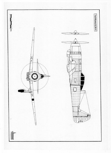
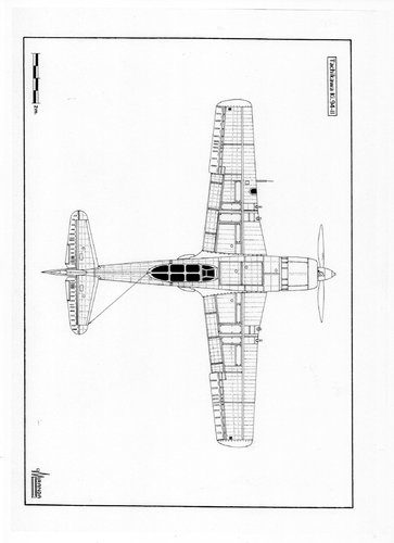
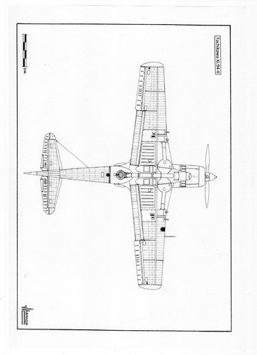
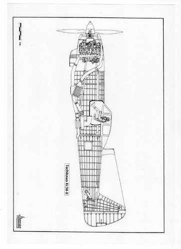
Tachikawa Ki-94-Ⅱ
- Thread starter blackkite
- Start date


blackkite
Don't laugh, don't cry, don't even curse, but.....
- Joined
- 31 May 2007
- Messages
- 9,515
- Reaction score
- 9,661
The Mamoru-Kai (Ha-46) was even more problematic and Nakajima was not able to overcome the motor’s teething difficulties. Consequently, Nakajima cancelled further work on the Mamoru-Kai.

- Joined
- 19 July 2016
- Messages
- 4,816
- Reaction score
- 4,276
Great results, thank you.
Mamoru-Kai was originally envisioned for things like the Kawanishi K-100.We know that the Mamoru (14-cylinder one) was eventually replaced by Kaisei for reliability reasons, thus cancelling development on the 18-cylinder Mamoru Kai.This happened fairly early on (like 1943-44, K-100 was a 17-shi compeititor).The first prototype of the Ki-94-II didn't finish construction until august 1945, let alone the second prototype.It doesn't make sense for the japanese to fit something that didn't work and was cancelled a long time ago into one of their new state-of-the-art prototype.The same engine (ha-46), was also know to use for Ki-87-II.Considering that they are compeititors with similar performance and dimensions, there's must be some truth to it.Perhaps japanese engineers finally manage to improve upon the ha-46 late in the war ?The Mamoru-Kai (Ha-46) was even more problematic and Nakajima was not able to overcome the motor’s teething difficulties. Consequently, Nakajima cancelled further work on the Mamoru-Kai.
Last edited:
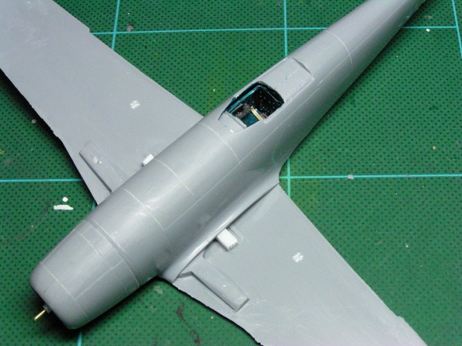
I have fallen in love with the KI-94 II! Who makes this specific kit?Another Ki-94Ⅱmodel bottom.(1/48 scale)
You can see oil cooler behind the propeller,exhaust gas duct from the engine to the turbo charger, intercoolers beside the exhaust gas duct, turbo charger and ram air intake at both side of the fuselage.
View attachment 620342」
https://www.webmodelers.com/201809ki94.html
I’ve been searching for a 1/48 scale and no luck. Where did you find it?Another Ki-94Ⅱmodel bottom.(1/48 scale)
You can see oil cooler behind the propeller,exhaust gas duct from the engine to the turbo charger, intercoolers beside the exhaust gas duct, turbo charger and ram air intake at both side of the fuselage.
View attachment 620342」
https://www.webmodelers.com/201809ki94.html
High-altitude interceptors Nakajima Ki.87 and Tachikawa Ki.94
On March 1938, the Mitsubishi A5M2 fighters fighting in China started to use mechanically driven superchargers and oxygen equipment to face the new Gloster Gladiator of the Chinese Air Force that could fly at altitude of 6,000 m.
These primitive forced induction devices, based on a French Patent Rateau of 1926, consisted of a rapidly spinning impeller powered by the engine, via a short drive shaft, that sucks in ambient air then injected it into the carburetor.
By acquiring the manufacturing license of the German engine Daimler Benz DB 601, the Japanese gained access to the Vulkan coupling technology, a supercharger fitted with continuously variable transmission device that automatically regulated the rotation speed of the impeller by means of a barometric control
The study of a Merlin XX British engine, from a Hawker Hurricane Mk.II captured in Singapore, allowed Kawasaki engineers to build their first two-stage supercharger for the Ha-140 engine. The British system used two impellers that rotated at different speeds selected by the pilot by means of a gearbox. The use of two impellers in engines of more than 1,500 hp requires the installation of an intercooler, to avoid the premature detonation problems that occur when air is injected into the carburetor at an excessive temperature.
In 1937 Japan acquired a turbocharger to the Swiss company Brown Boveri & Cie and, based on the Swiss model, the Hitachi, Nakajima and Mitsubishi engineers received the assignment to develop their own turbocharger. By the end of 1942, Mitsubishi produced the mechanically driven Ru-302 supercharger, with two-stages and two-speeds, for the Ki.46-IV high-altitude reconnaissance airplane. The Ru-302 did not perform well during the tests, conducted in May 1944 with a J2M4 Raiden-33 fighter. The Hitachi turbo was manufactured with the best available alloys of chrome-molybdenum steel, but its development was too slow and was still being tested, installed in a C6N Saiun, by the end of World War II.
The Nakajima team tried to modify an A6M2 by installing a Sakae turbocharged engine without an intercooler. The prototype was named A6M4 and started its flight test at Yokosuka Arsenal in 1943, experiencing fires and multiple ruptures in compressor and ducting. The origin of these failures was that the imported Swiss turbo was actually a design for diesel 500 hp engines with operating temperature that was 200 degrees Celsius lower than that of petrol Japanese engines. Despite all these problems, the Mitsubishi engineers managed to build the A6M3 series in 1942, powered by a Sakae 21 and able to climb up to 11,000 m thanks to a modest two-speed supercharger.
The Japanese tried to increase the power of their engines with Methanol-water and oxygen injection devices, but the system only worked below 10,000 m. Mitsubishi engineers tried to develop an exhaust-driven turbo-supercharger based on the study of North American P-43 and B-17 aircraft captured in China and Philippines. By mid-1944 turbo-superchargers were indispensable to fight the B-29 bombers at altitudes over 10,000 m, but the Japanese industry was unable to duplicate the captured airplanes.
The General Electric turbo-supercharger was a product that required enormous technical and manufacturing resources that were not available in Japan. The high temperatures reached by exhaust gas and the high rotation speeds of turbines (26,000 rpm) required the use of austenitic stainless steel chrome-molybdenum alloys and the development of work-hardening techniques that enabled the turbo-charger to withstand stresses caused by centrifugal forces. The precision machining of turbines and impellers could only be made possible by sophisticated machine tools and surplus of raw materials.
Availability of high-octane fuel let the American engines run hotter without detonation problems, but the Japanese had 87-octane only and should use forced air cooling fans to avoid the overheating of their supercharged engines.
In August 1944 the Mitsubishi J2M4 Raiden 34 flew with one Ru-303 exhaust-driven turbo-supercharger mounted in the starboard side of the fuselage, just behind the Kasei 23c engine. The new supercharger did not work properly either, provoking fires during the tests, and never became operational.
The exhaust-driven turbo-superchargers were larger, involved extra piping and increasing an aircraft size, weight, complexity and cost. It is not possible to install them in a conventional single engine fighter and it use requires airplanes specially designed, with enough room for installation of the turbo, the intercooler and the heavy tubing system.
In February 1942, the U.S. Government placed an order for 1,600 Boeing B-29 super bombers, able to fly at 595 kph and 9,700 m of altitude. In April, the Koku Hombu Technical Branch issued a specification calling for a high-altitude interceptor with 800 km/h max speed, 13,000 m service ceiling and 3,000 km range, armed with four 30 mm cannons. The specification was so demanding that most Japanese aircraft manufacturers decided not to submit projects.
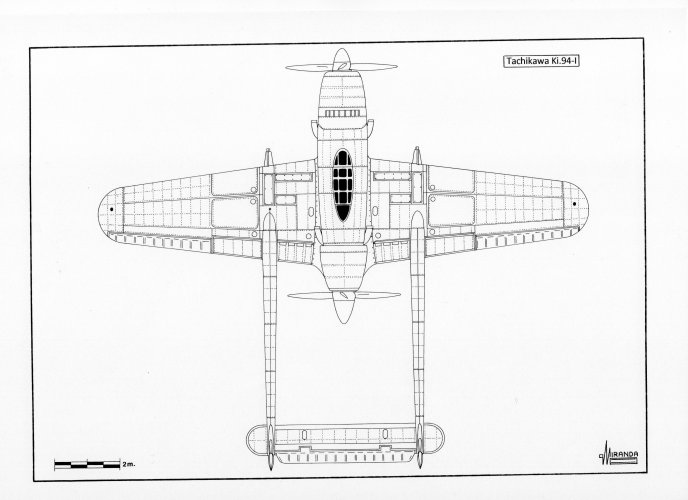
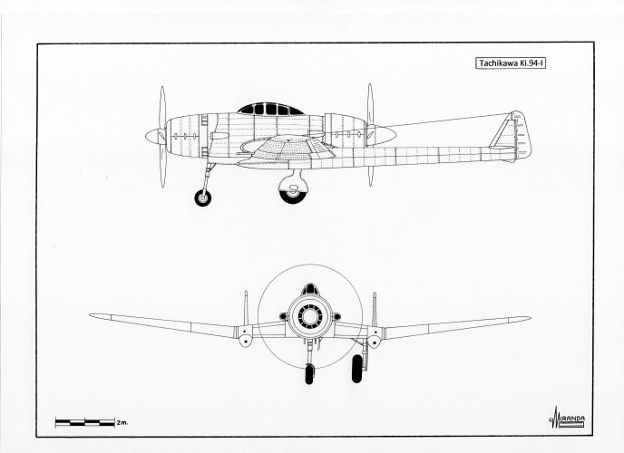
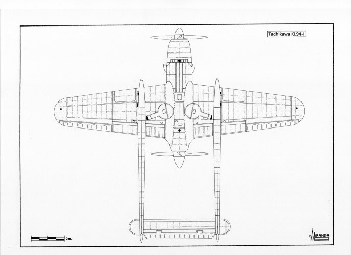
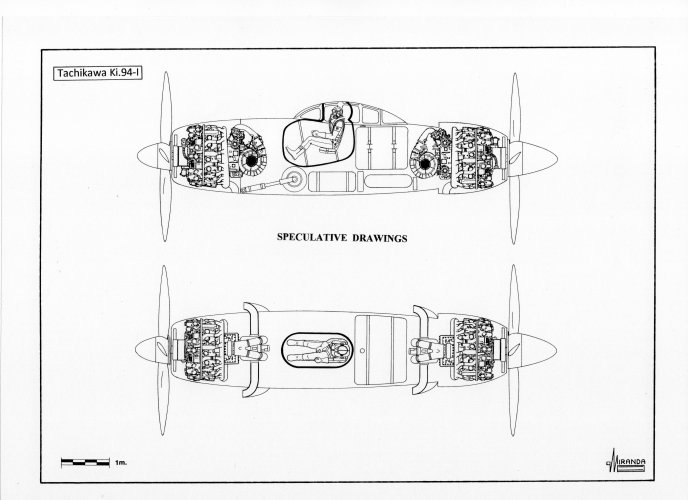
In the summer of 1942, the Tachikawa firm began the design of the Ki.94-I, a twin booms heavy fighter powered by two 2,000 hp Ha-211 Ru air-cooled radial engines (mounted in push-pull configuration) driving two VDM constant-speed propellers with 3.32 m of diameter. With the use of the new Ru-302 mechanically-driven superchargers, a service ceiling of 14,000 m was expected. In October 1943, the mock-up was presented to Koku Hombu, but IA experts decided that the plane was too heavy and with an overly complex propulsion system. The project was dropped.
Ki.94-I technical data
Wingspan: 15 m, length: 13.05 m, height: 3.85 m, wing area: 37 sq. m, max speed: 780 km/h, max weight: 9,400 kg, ceiling: 14,000 m, range: 4,520 km. Proposed armament: 2x37 mm Ho-203 and 2x30 mm Ho-105 cannons.
The IJA intelligence services awaited the first B-29 attack in April 1944, but this was delayed by lack of supplies at the Chinese airfields of Kweiling and Liuchow. The first contact with the B-29 occurred in 26 April, when six Ki.43 fighters of the IJA 204th Sentai had a worrying combat with a B-29 of the 444th B.G., which was flying supplies from India to China. The giant plane, heavily loaded and with the tail gun off service, was shot 12 times without apparent results, it just ascended until the Hayabusas were forced to abandon the pursuit by lack of oxygen.
It was known that the B-29 could fly at high altitudes thanks to its turbocharged engines, but when it first appeared 10,000 m above Tokyo on a reconnaissance mission, it was flying so fast that the Ki.44 of the 47th Sentai could not reach it. By contrast, the J2M4, J2M5 and N1K5-J fighters, that had been designed to face it, had not even begun to be manufactured.
In March 1944 the IJA decided to lower the requirements for the high-altitude specification of 1942, asking the Nakajima firm to build the Ki.87-I, a high-altitude interceptor with a less heavy pressurization system than the Tachikawa pressure cabin.
Three versions of the Nakajima fighter are known: the Ki.87-I, the Ki.87-II, powered by one 3,000 hp Ha-46 engine (with Ru-303) driving a six-bladed propeller and the Nakajima 20-Shi-Ko, with Ha-44-21 engine developed for the IJN. The Ki.87-I prototype was flown in April 1945, powered by one 2,450 hp Ha-44-12 air cooled radial engine, with one Ru-303 turbo-supercharger mounted at the starboard side of the forward fuselage.
This configuration seemed safer than the ventral position installation. Mitsubishi engineers feared that the fuel contact with the turbo would cause fires. In 1942 the Chinese lost 139 P-43 fighters for this cause, due to a defect in the Fairplane cement used to seal the fuel tanks. The IJA disagreed and preferred a ventral installation, such as in the P-47 Thunderbolt, which delayed serial production of the Ki.87 until the end of the war. Nakajima preferred to devote its efforts to obtaining a high-altitude interceptor based on the Hayate airframe and yielded its pressurization technology to Tachikawa so that they could use it in the design of the Ki.94-II.
Ki.87-I technical data
Wingspan: 13.423 m, length: 11.82 m, height: 4.50 m, wing area: 26.0 sq. m, max speed: 697 km/h, max weight: 5,633 kg, ceiling: 12,855 m. Proposed armament: 2x30 mm (synchronized) Ho-155 and 2x20 mm Ho-5 cannons.
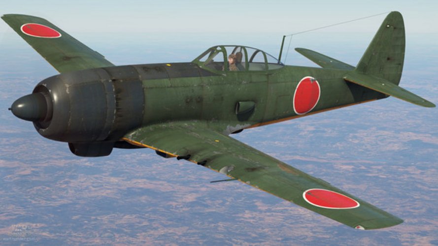
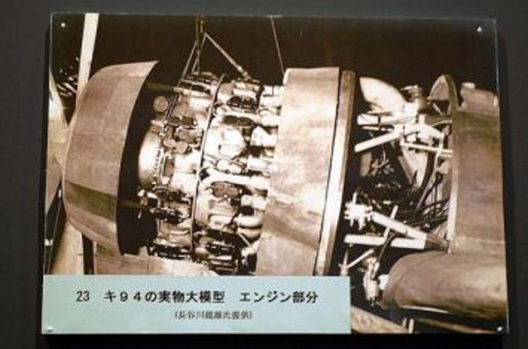
The Ki.94-II design was approved by the Koku Hombu in April 1944. An order was placed for three prototypes and eighteen pre-production aircraft. The aircraft was equipped with laminar flow wings, designed by Tatsuo Hasegawa, and one Nakajima pressurized cabin with armored windshield. The engine used was a 2,450 hp Ha-44-13 (with Ru-303, cooling fan and two intercoolers) driving a four-bladed propeller. The prototype was completed in July 1945, but it was not fly tested because the war ended.
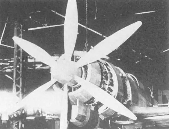
A second prototype, in construction phase, was powered by one 3,000 hp Ha-46 engine, driving a six-bladed VDM/Sumitomo airscrew with 3.8 m of diameter. Development of the Ki.94 was too slow and when the B-29s attacked Yawata-Kyushu on 14 June 14 1944, Japan had no fighters capable of confronting them successfully.
Ki.94-II technical data
Wingspan: 13.4 m, length: 12 m, height: 4.61 m, wing area: 28 sq. m, max speed: 720 km/h, max weight: 6.427 kg, ceiling: 14,250 m, range: 2,200 km. Proposed armament: 2x30 mm Ho-155 and 2x20 mm Ho-5 cannons.
blackkite
Don't laugh, don't cry, don't even curse, but.....
- Joined
- 31 May 2007
- Messages
- 9,515
- Reaction score
- 9,661
The main wing
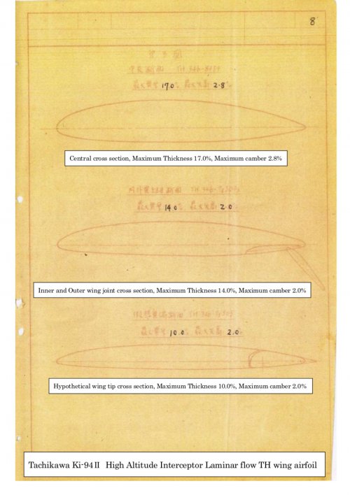
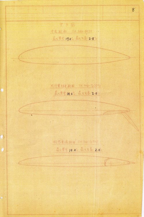
The main wing is a single-spar structure (with auxiliary spars) for ease of production and to ensure sufficient space for wing storage. The inner and outer wings are split, with the joint located midway between the two fixed armament guns per wing, and this is also where the wing leading edge line bends forward to allow the main wheels (90 cm diameter) to retract. The main spars run in a straight line at 30% chord, but due to this leading edge overhang, they deviate from 30% from the inner wing toward the wing root. The wing trailing edge line is in a straight line from root to tip, and the auxiliary spars run parallel to this trailing edge line regardless of chord, prioritizing the capacity of the in-wing fuel tanks and the intercooler space between the spars inside the fuselage. As a result, the flap chord length (front-to-back length) is consistent from end to end, and even the cross-sectional shape (rib material) is standardized, improving productivity. This simplified design was made possible by the laminar flow wing "TH airfoil" that Hasegawa Tatsuo independently researched and developed. By taking advantage of the fact that the trailing edge is thicker than that of a normal airfoil, the slide rails of the zap flap can be contained within the wing without being exposed to the outside, and the auxiliary spar can also be made sufficiently strong.
Furthermore, a smooth leading edge is crucial for a laminar flow wing to achieve its aerodynamic performance. This aircraft's skin was thickened to approximately 1.6 mm, and the longerons (stringers) were eliminated, relying solely on ribs for support. The extensive use of spot welding minimized the number of rivets. This not only achieved a smooth surface but also simplified the manufacturing process, a design suited to the challenging domestic situation at the time. The zap flaps, a wood-metal composite wing and fabric-covered structure, also contributed to saving on light alloys. These flaps were specially designed for use during high-altitude turns in addition to takeoff and landing. At high altitudes, where the air is thin, the wings generate less lift, and a sharp turn would quickly result in a loss of altitude, wasting time and fuel to regain the same altitude. The zap flaps on this aircraft were deployed during turns to supplement lift and allow for tight turns without losing altitude. The wing angle is also large, at 3 degrees, to accommodate high-altitude flight, eliminating the need for the aircraft to fly in an excessively upward tilt, reducing the pilot's visibility and preventing insufficient elevator effectiveness. The reason the ailerons protrude rearward from the trailing edge of the TH airfoil, as seen in the top view, is because the rear end of the TH airfoil is pointed like a standard airfoil.
The main wing is a single-spar structure (with auxiliary spars) for ease of production and to ensure sufficient space for wing storage. The inner and outer wings are split, with the joint located midway between the two fixed armament guns per wing, and this is also where the wing leading edge line bends forward to allow the main wheels (90 cm diameter) to retract. The main spars run in a straight line at 30% chord, but due to this leading edge overhang, they deviate from 30% from the inner wing toward the wing root. The wing trailing edge line is in a straight line from root to tip, and the auxiliary spars run parallel to this trailing edge line regardless of chord, prioritizing the capacity of the in-wing fuel tanks and the intercooler space between the spars inside the fuselage. As a result, the flap chord length (front-to-back length) is consistent from end to end, and even the cross-sectional shape (rib material) is standardized, improving productivity. This simplified design was made possible by the laminar flow wing "TH airfoil" that Hasegawa Tatsuo independently researched and developed. By taking advantage of the fact that the trailing edge is thicker than that of a normal airfoil, the slide rails of the zap flap can be contained within the wing without being exposed to the outside, and the auxiliary spar can also be made sufficiently strong.
Furthermore, a smooth leading edge is crucial for a laminar flow wing to achieve its aerodynamic performance. This aircraft's skin was thickened to approximately 1.6 mm, and the longerons (stringers) were eliminated, relying solely on ribs for support. The extensive use of spot welding minimized the number of rivets. This not only achieved a smooth surface but also simplified the manufacturing process, a design suited to the challenging domestic situation at the time. The zap flaps, a wood-metal composite wing and fabric-covered structure, also contributed to saving on light alloys. These flaps were specially designed for use during high-altitude turns in addition to takeoff and landing. At high altitudes, where the air is thin, the wings generate less lift, and a sharp turn would quickly result in a loss of altitude, wasting time and fuel to regain the same altitude. The zap flaps on this aircraft were deployed during turns to supplement lift and allow for tight turns without losing altitude. The wing angle is also large, at 3 degrees, to accommodate high-altitude flight, eliminating the need for the aircraft to fly in an excessively upward tilt, reducing the pilot's visibility and preventing insufficient elevator effectiveness. The reason the ailerons protrude rearward from the trailing edge of the TH airfoil, as seen in the top view, is because the rear end of the TH airfoil is pointed like a standard airfoil.
Last edited:
blackkite
Don't laugh, don't cry, don't even curse, but.....
- Joined
- 31 May 2007
- Messages
- 9,515
- Reaction score
- 9,661
Attachments
Last edited:
blackkite
Don't laugh, don't cry, don't even curse, but.....
- Joined
- 31 May 2007
- Messages
- 9,515
- Reaction score
- 9,661
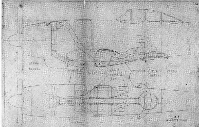
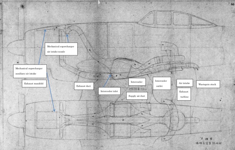
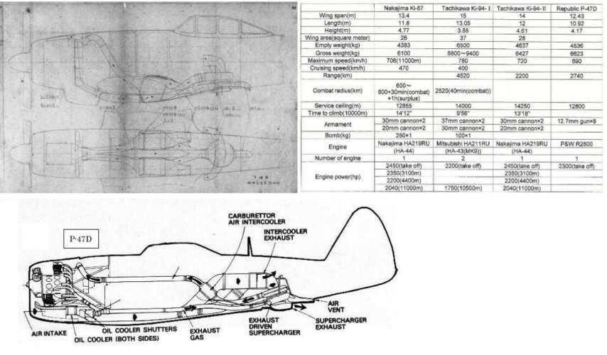
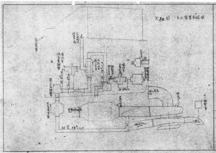
Hi! Ki-94Ⅱ engine air supply and exhaust system.
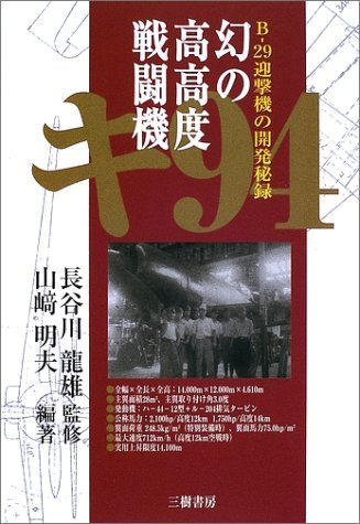
Source : 幻の高高度戦闘機キ94(Mirage high altitude fighter ki-94), MIKI PRESS, 2002-9-25, ISBN4-89522-299-3,Chief designer Tatso Hasegawa supervision.
Source : 幻の高高度戦闘機キ94(Mirage high altitude fighter ki-94), MIKI PRESS, 2002-9-25, ISBN4-89522-299-3,Chief designer Tatso Hasegawa supervision.
Attachments
Last edited:
blackkite
Don't laugh, don't cry, don't even curse, but.....
- Joined
- 31 May 2007
- Messages
- 9,515
- Reaction score
- 9,661
Tatsuo Hasegawa TOYOTA
https://global.toyota/jp/corolla50th/message/hasegawa/
https://global.toyota/en/corolla50th/
https://global.toyota/jp/corolla50th/message/hasegawa/
https://global.toyota/en/corolla50th/
blackkite
Don't laugh, don't cry, don't even curse, but.....
- Joined
- 31 May 2007
- Messages
- 9,515
- Reaction score
- 9,661
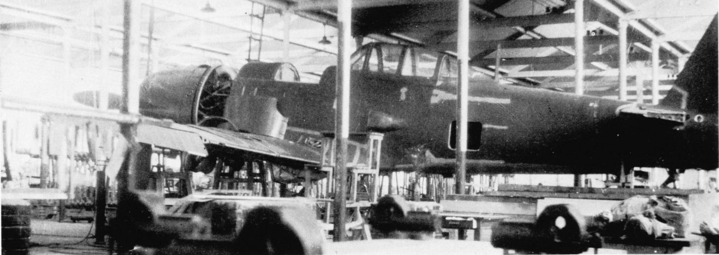
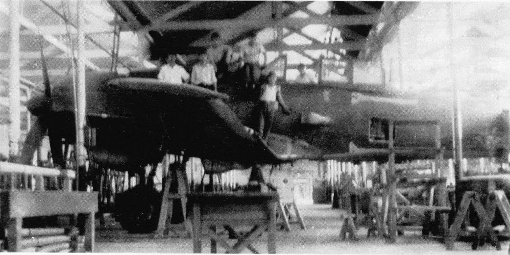
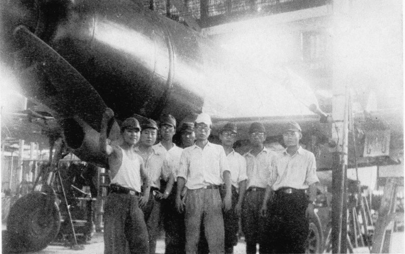
The completed Ki-94 II was removed from the Kanamachi Plant by an American technical investigation team.
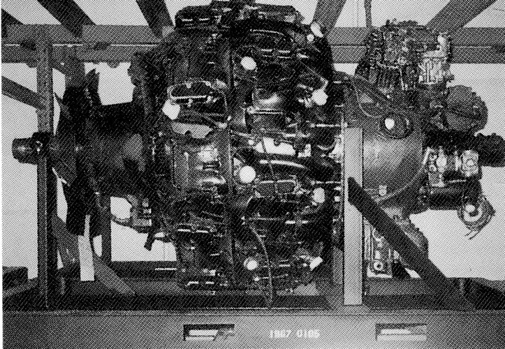
Once in the United States, the Ki-94 II was sent to an aircraft depot in Middletown, Pennsylvania. In 1949, it was moved to Park Ridge, near Chicago, and its whereabouts are unknown. It was intended to become a museum property, but this did not happen. The Ki-94 II was last photographed at Park Ridge with its engine removed. That engine, HA44-12, is kept at the Smithsonian Institution in Washington.
Also The Ki-83 was transported to the US mainland and underwent technical inspections, but details of its subsequent fate are unknown. It is believed to have ultimately been incinerated.
Once in the United States, the Ki-94 II was sent to an aircraft depot in Middletown, Pennsylvania. In 1949, it was moved to Park Ridge, near Chicago, and its whereabouts are unknown. It was intended to become a museum property, but this did not happen. The Ki-94 II was last photographed at Park Ridge with its engine removed. That engine, HA44-12, is kept at the Smithsonian Institution in Washington.
Also The Ki-83 was transported to the US mainland and underwent technical inspections, but details of its subsequent fate are unknown. It is believed to have ultimately been incinerated.
Last edited:
blackkite
Don't laugh, don't cry, don't even curse, but.....
- Joined
- 31 May 2007
- Messages
- 9,515
- Reaction score
- 9,661
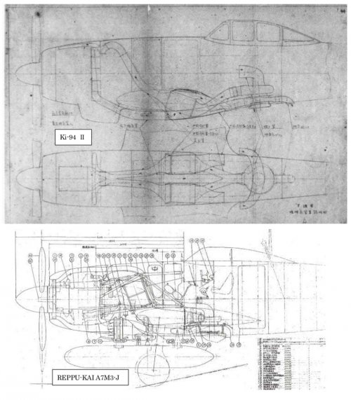
Intake system:
Intake air enters through both side walls of the center fuselage and enters the exhaust turbine. Pressurized by a centrifugal compressor coaxially connected to the exhaust turbine, the intake air is cooled by two intercoolers mounted on the underside of the fuselage in the center of the main wing. Just before the engine, the air recombines into a single intake pipe and enters the mechanical supercharger at the rear of the engine. The intercooler is a circular-pipe, orthogonal type with ample cold air intakes on the underside of the fuselage. When dust protection is particularly required at low altitudes, it is automatically switched to the forward air intake, which opens into the engine nacelle. A flap is attached to the intercooler cold air outlet, and a prototype was underway with plans to equip it with an automatic temperature control device that would maintain the intake air temperature at approximately ○°C.
Exhaust system:
The exhaust pipes branch and collect into one at the bottom of the fuselage, then enter the turbine exhaust case. The exhaust relief port is located behind the exhaust turbine, and the distance from the exhaust pipe to the turbine exhaust case inlet is approximately 3,700 mm, eliminating the risk of the exhaust turbine overheating. An air preheating chamber for warming the cannon is located midway through the rear exhaust pipe. The exhaust pressure regulator is located above and behind the exhaust turbine.
Intake air enters through both side walls of the center fuselage and enters the exhaust turbine. Pressurized by a centrifugal compressor coaxially connected to the exhaust turbine, the intake air is cooled by two intercoolers mounted on the underside of the fuselage in the center of the main wing. Just before the engine, the air recombines into a single intake pipe and enters the mechanical supercharger at the rear of the engine. The intercooler is a circular-pipe, orthogonal type with ample cold air intakes on the underside of the fuselage. When dust protection is particularly required at low altitudes, it is automatically switched to the forward air intake, which opens into the engine nacelle. A flap is attached to the intercooler cold air outlet, and a prototype was underway with plans to equip it with an automatic temperature control device that would maintain the intake air temperature at approximately ○°C.
Exhaust system:
The exhaust pipes branch and collect into one at the bottom of the fuselage, then enter the turbine exhaust case. The exhaust relief port is located behind the exhaust turbine, and the distance from the exhaust pipe to the turbine exhaust case inlet is approximately 3,700 mm, eliminating the risk of the exhaust turbine overheating. An air preheating chamber for warming the cannon is located midway through the rear exhaust pipe. The exhaust pressure regulator is located above and behind the exhaust turbine.
Last edited:
blackkite
Don't laugh, don't cry, don't even curse, but.....
- Joined
- 31 May 2007
- Messages
- 9,515
- Reaction score
- 9,661
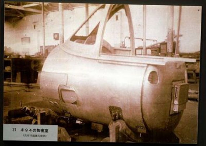
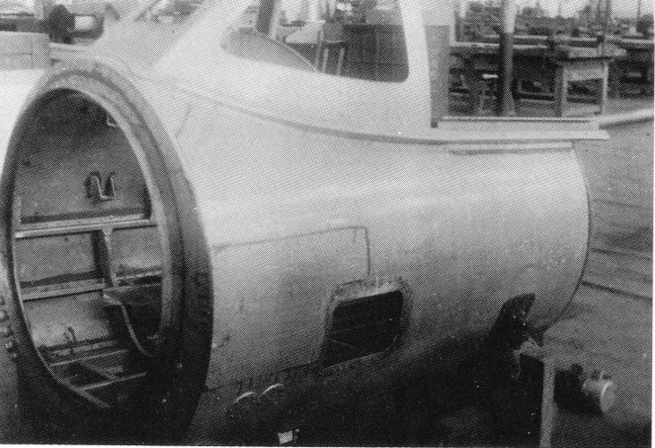
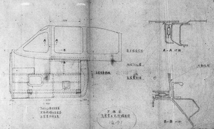
The airtight pressurized compartment, another important element of a high-altitude fighter, was another advantage the Ki-94 had over other models.
The airtight compartment was separate from the fuselage structure, and the goal was to reduce the physical strain on the single-seat pilot as much as possible, so it was not very airtight and pressurization was kept to a minimum by using oxygen in addition.
This was in consideration of the possibility of the air in the airtight compartment escaping if the pilot was hit by a bullet.
The ventilation volume of the airtight compartment for pressurization was adjusted to 1,000 liters per minute, and the incoming air was blown onto the windshield to prevent fogging, similar to a modern-day car defroster.
The airtight compartment was separate from the fuselage structure, and the goal was to reduce the physical strain on the single-seat pilot as much as possible, so it was not very airtight and pressurization was kept to a minimum by using oxygen in addition.
This was in consideration of the possibility of the air in the airtight compartment escaping if the pilot was hit by a bullet.
The ventilation volume of the airtight compartment for pressurization was adjusted to 1,000 liters per minute, and the incoming air was blown onto the windshield to prevent fogging, similar to a modern-day car defroster.
Attachments
blackkite
Don't laugh, don't cry, don't even curse, but.....
- Joined
- 31 May 2007
- Messages
- 9,515
- Reaction score
- 9,661
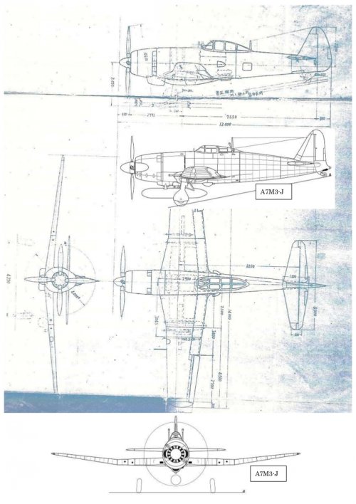
The Ki-94 II, which did not fly for very long periods, was pressurized to the minimum extent necessary for combat flight by using oxygen masks in combination. No dedicated blower was installed to pressurize the airtight chamber, but rather a portion of the engine intake air that passed through the exhaust turbine was used. The interior altitude of the airtight chamber was set at 6,000 m within the range of the engine supercharger's first gear, and 9,000 m within the range of the engine supercharger's second gear. The airtight chamber and the movable parts of the windshield were kept airtight with pressurized rubber tubes.
Attachments
blackkite
Don't laugh, don't cry, don't even curse, but.....
- Joined
- 31 May 2007
- Messages
- 9,515
- Reaction score
- 9,661
Engineer Hasegawa of Tachikawa Aircraft Company devised an original TH laminar flow wing and its analytical method, which he applied to the Ki-94 II. The TH laminar flow wing was distinct from the LB wing developed by Professor Ichiro Tani of the Aeronautical Research Institute of Tokyo Imperial University. The TH laminar flow wing had a small radius at the leading edge and a maximum wing thickness of approximately 45% of the chord. While this was similar to typical laminar flow wings of the time, the TH laminar flow wing's unique feature was the addition of a small radius at the trailing edge, increasing overall thickness. Conventional airfoils with sharp trailing edges required complex algebraic calculations and were prone to calculation errors. However, adding a radius to the trailing edge eliminated singularities, allowing for the use of differential equations using Fourier series. This reduced the amount of calculation work required by actual aircraft designers and improved the aerodynamic reliability of the airfoil.
blackkite
Don't laugh, don't cry, don't even curse, but.....
- Joined
- 31 May 2007
- Messages
- 9,515
- Reaction score
- 9,661
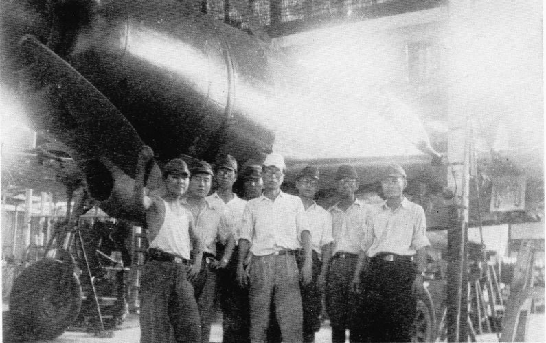
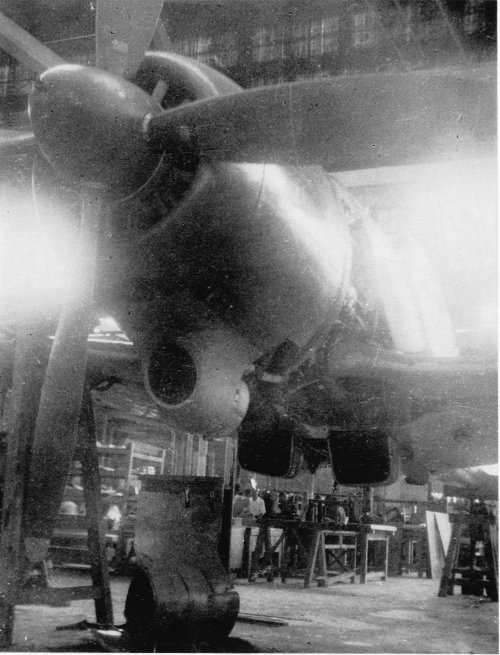
The sole completed prototype of the Tachikawa Ki-94-II was brought to the United States after World War II and was subsequently scrapped without ever flying, most likely around 1950 in Park Ridge, Illinois. Although a few sources mention it being transferred to a museum, the consensus is that it was examined and then destroyed. (AI)
blackkite
Don't laugh, don't cry, don't even curse, but.....
- Joined
- 31 May 2007
- Messages
- 9,515
- Reaction score
- 9,661
Attachments
blackkite
Don't laugh, don't cry, don't even curse, but.....
- Joined
- 31 May 2007
- Messages
- 9,515
- Reaction score
- 9,661
Hi!
https://japanese-warship.com/photo/ki94-photo/
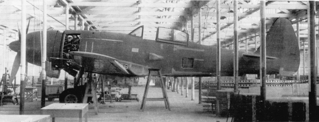
The American team that came to plunder the Shinden took a variety of photos of the Shinden, but the team that came to plunder the Ki-94 II not only took no photos of it, but also scrapped it in the US. They also proudly showed off photos of the P-80 to Chief Designer Hasegawa. They were a terrible bunch of people, and it was impossible to understand what they were up to.
Good children should not become adults like this.
https://japanese-warship.com/photo/ki94-photo/
The American team that came to plunder the Shinden took a variety of photos of the Shinden, but the team that came to plunder the Ki-94 II not only took no photos of it, but also scrapped it in the US. They also proudly showed off photos of the P-80 to Chief Designer Hasegawa. They were a terrible bunch of people, and it was impossible to understand what they were up to.
Good children should not become adults like this.
Attachments
Last edited:
Similar threads
-

-
other less known japanese aircraft projects
- Started by airman
- Replies: 14
-
 Tachikawa A26 (Ki-77) Experimental Long-Range Aircraft
- Started by blackkite
- Replies: 44
-
-
 Japanese Secret Projects:Experimental Aircraft of the IJA & IJN 1939-1945
- Started by Pelzig
- Replies: 261