Maury Markowitz

From the Great White North!
Joined
27 February 2014
Messages
211
Reaction score
172
I'm putting together an article on the Wireless Set No. 10, which deserves to be MUCH better known - it was the first TDM and PCM comms system in the world. Sadly there is very little info on it, but I know that "Wireless for the Warrior" had a relatively detailed description including post-war development. Does anyone have a copy?
 
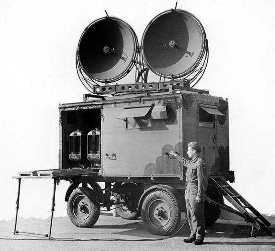
Not me I'm afraid. I have however come across a image of the Wireless Set No. 10 on his website, though you quite likely will have already seen it:
1626280391272.png
Wireless Set No. 10 was a mobile radio relay system developed in about 1944. Use: Line of Communications radio relay providing 8 duplex telephone channels. Frequency band 4.4/4.8 GHz. Range 50 miles (optical). Pulse width modulation.
 
On a side note, there is a brief mention of it over at the Royal Signals Museum website:

The importance of the No10 set​

As the Allies moved through North West Europe, Royal Signals laid hundreds of miles of telephone and telegraph cables and made use of civilian networks wherever possible. Communications to the United Kingdom were made via a cable laid under the Channel connected to signal stations at Bayeaux and Cherbourg.

The No. 10 set made use of newly developed radar techniques to carry eight channels over any obstacles between land and line links. Numerous radio sets are on display in the Museum including the original No. 10 set.
EDIT: Found a little more on it on another part of the site:

23) No 10 Wireless Set​

WW2 UHF Multi-channel set- The precurser to BRUIN and Ptarmigan radio relay equipment
The Wireless Set Number 10 provided 8 duplex speech channels using multiplexers and pulse code modulation (PCM) which was very advanced in 1944. The antenna was a UHF parabolic reflector emitting a narrow beam of approximately 5 degrees. It was first used some weeks after D Day for a link between The Isle of Wight to Cherbourg in France. However, as many Royal Signallers, who have had to struggle with Path Profile Analysis, this link was at the limit of the set’s Fresnel Zone – Communications therefore were only intermittent. Later it was used in a tactical role to support HQ 21 Army Group. Its success was initially limited owing to the lack of working sets and a lack of 60 Feet masts – a familiar problem to all Royal Signals. However, soon the Signals Detachments managed to establish reliable radio relay chains across Europe even to Montgomery’s final headquarters on Luneburg Heath in Northern Germany. Here is a high spot between Munster and Minden, called the IBURG:

I also found elsewhere what seems to be a developmental prototype from 1943:
https://www.radiomuseum.org/r/mil_gb_wireless_set_no10.html
 
Last edited:
I'm putting together an article on the Wireless Set No. 10, which deserves to be MUCH better known - it was the first TDM and PCM comms system in the world. Sadly there is very little info on it, but I know that "Wireless for the Warrior" had a relatively detailed description including post-war development. Does anyone have a copy?
I just happened on this while making a last scan to look for information to archive on wireless set number 10. I edited the wikipedia page today, it had been on my to-do list for a long time, and I had spare time today. I'm sorry that it looks like I undid some of your edits. You may not see this, but the information maybe be useful for someone else who happens upon this short thread.

Yes, there are references to the device using PCM for the first time. The problem is that this is so unlikely that it's almost certainly not true that it utilized PCM, and also there are better references that say it used PWM, which would be the obvious choice. In fact, part of the wikipedia article that attributed PCM goes on to describe PWM:

"The sine wave was processed in a series of tubes to produce a sawtooth wave, which was then gated by the audio signal. When the voltage of the sawtooth was above the voltage of the audio signal, an output pulse was produced – the higher the voltage of the audio signal, the smaller the width of the sawtooth above that level, and the shorter the pulse. The final output was a train of pulses at the 9 kHz reference frequency, the width of each pulse being inversely proportional to the audio signal voltage."

The one "external reference" that was already in the article links for a very short webpage that says it used PWM ("Wireless set No. 10...pulse width modulation..."). A much better reference is the paper titled A Brief History of Microwave Radio Fixed Point to Point (Relay) Communications Systems (catchy, huh?). Unfortunately, it's a for-pay paper via IEEE Explorer, but I found an excerpt regarding Wireless Set Number 10, that says it used PWM:

"The first microwave radio relay system radios were the British Wireless Set No. 10 developed by the UK Signals Research and Development Establishment (SRDE). The Pye Company built the RF section and the TMC Company built the multiplex. It was an eight-telephone-channel TDM pulse width modulation 5-GHz radio system designed to operate in tandem as a radio relay. It was demonstrated to the US Signal Corps Labs and Bell Laboratories on September 1942. This spurred the development of similar systems in the United States: the RCA AN/TRC-5 and the Bell Labs AN/TRC-6 (Carl, 1966; Fagen, 1978; Sobol, 1984)."

On the flip-side, there is no simple way to transmit PCM, a digital protocol, in the 1940s. And there is no reason to convert voice to digital in that particular use anyway. PWM fit the bill perfectly, because it's an analog modulation (converting amplitude to pulse width) that could take advantage of the magnetron, the key transmitting device available for the device. The magnetron could only toggle from off to on, quickly, so it was perfectly suited to transmitting pulses, with no synchronization necessary.

 
I just happened on this while making a last scan to look for information to archive on wireless set number 10. I edited the wikipedia page today, it had been on my to-do list for a long time, and I had spare time today. I'm sorry that it looks like I undid some of your edits. You may not see this, but the information maybe be useful for someone else who happens upon this short thread.

Yes, there are references to the device using PCM for the first time. The problem is that this is so unlikely that it's almost certainly not true that it utilized PCM, and also there are better references that say it used PWM, which would be the obvious choice. In fact, part of the wikipedia article that attributed PCM goes on to describe PWM:

"The sine wave was processed in a series of tubes to produce a sawtooth wave, which was then gated by the audio signal. When the voltage of the sawtooth was above the voltage of the audio signal, an output pulse was produced – the higher the voltage of the audio signal, the smaller the width of the sawtooth above that level, and the shorter the pulse. The final output was a train of pulses at the 9 kHz reference frequency, the width of each pulse being inversely proportional to the audio signal voltage."

The one "external reference" that was already in the article links for a very short webpage that says it used PWM ("Wireless set No. 10...pulse width modulation..."). A much better reference is the paper titled A Brief History of Microwave Radio Fixed Point to Point (Relay) Communications Systems (catchy, huh?). Unfortunately, it's a for-pay paper via IEEE Explorer, but I found an excerpt regarding Wireless Set Number 10, that says it used PWM:

"The first microwave radio relay system radios were the British Wireless Set No. 10 developed by the UK Signals Research and Development Establishment (SRDE). The Pye Company built the RF section and the TMC Company built the multiplex. It was an eight-telephone-channel TDM pulse width modulation 5-GHz radio system designed to operate in tandem as a radio relay. It was demonstrated to the US Signal Corps Labs and Bell Laboratories on September 1942. This spurred the development of similar systems in the United States: the RCA AN/TRC-5 and the Bell Labs AN/TRC-6 (Carl, 1966; Fagen, 1978; Sobol, 1984)."

On the flip-side, there is no simple way to transmit PCM, a digital protocol, in the 1940s. And there is no reason to convert voice to digital in that particular use anyway. PWM fit the bill perfectly, because it's an analog modulation (converting amplitude to pulse width) that could take advantage of the magnetron, the key transmitting device available for the device. The magnetron could only toggle from off to on, quickly, so it was perfectly suited to transmitting pulses, with no synchronization necessary.
I am currently collecting information on the WS10 system with a view to restore 2 WS10 receivers over the winter
so i would like any input that i can get from others and it is PWM that was used
Regards Paul Bicknell south coast UK
 
I just happened on this while making a last scan to look for information to archive on wireless set number 10. I edited the wikipedia page today, it had been on my to-do list for a long time, and I had spare time today. I'm sorry that it looks like I undid some of your edits. You may not see this, but the information maybe be useful for someone else who happens upon this short thread.

Yes, there are references to the device using PCM for the first time. The problem is that this is so unlikely that it's almost certainly not true that it utilized PCM, and also there are better references that say it used PWM, which would be the obvious choice. In fact, part of the wikipedia article that attributed PCM goes on to describe PWM:

"The sine wave was processed in a series of tubes to produce a sawtooth wave, which was then gated by the audio signal. When the voltage of the sawtooth was above the voltage of the audio signal, an output pulse was produced – the higher the voltage of the audio signal, the smaller the width of the sawtooth above that level, and the shorter the pulse. The final output was a train of pulses at the 9 kHz reference frequency, the width of each pulse being inversely proportional to the audio signal voltage."

The one "external reference" that was already in the article links for a very short webpage that says it used PWM ("Wireless set No. 10...pulse width modulation..."). A much better reference is the paper titled A Brief History of Microwave Radio Fixed Point to Point (Relay) Communications Systems (catchy, huh?). Unfortunately, it's a for-pay paper via IEEE Explorer, but I found an excerpt regarding Wireless Set Number 10, that says it used PWM:

"The first microwave radio relay system radios were the British Wireless Set No. 10 developed by the UK Signals Research and Development Establishment (SRDE). The Pye Company built the RF section and the TMC Company built the multiplex. It was an eight-telephone-channel TDM pulse width modulation 5-GHz radio system designed to operate in tandem as a radio relay. It was demonstrated to the US Signal Corps Labs and Bell Laboratories on September 1942. This spurred the development of similar systems in the United States: the RCA AN/TRC-5 and the Bell Labs AN/TRC-6 (Carl, 1966; Fagen, 1978; Sobol, 1984)."

On the flip-side, there is no simple way to transmit PCM, a digital protocol, in the 1940s. And there is no reason to convert voice to digital in that particular use anyway. PWM fit the bill perfectly, because it's an analog modulation (converting amplitude to pulse width) that could take advantage of the magnetron, the key transmitting device available for the device. The magnetron could only toggle from off to on, quickly, so it was perfectly suited to transmitting pulses, with no synchronization necessary.
The circuit diagrams and associated technical manuals show that the system uses what could best be described strictly as pulse duration modulation, although pulse width mod is close enough. The Mk2 used two velocity-modulated Heil tubes in a main/aux pair rather than the primitive split-anode CV79/89 glass magnetron of the original version. In the Mk2, the modulation pulses were applied to the control/screen grids of the active V246A/1K Heil tube rather than the brute-force anode shunt modulation in the Mk1. There is a sync pulse for the start of each frame that lasts 20 microseconds, then eight variable-length pulses, each with an overall duration of 10.5 microseconds, consisting of a space of mean duration 7 microseconds and and a variable length mark pulse with a mean duration of 3.5 microseconds, varying with the instantaneous value of that channel's audio signal. Eight data pulses from seven sampled audio channels plus a supervisory channel are sent, then another 7 microsecond space for a total frame length of 113 microseconds. That's about 9 kHz frame frequency, enough to give a non-aliased audio output of up to 3 kHz. The pulse rise/fall times were, of necessity, very short, so the required bandwidth was many megahertz. The silver-plated cavities used were fairly lightly loaded, but even at a loaded Q-factor of several hundred, the rise/fall time of the resonance at 4.65 GHz would be shorter than that of the grid pulses. The Mk1 used four parallel resistors to pull the magnetron anode up to full HT, then turned on a high-powered tetrode wired in parallel with the anode to pull the HT voltage low so the oscillation was quenched. In the Mk2, the modulation used the characteristic behaviour of the Heil tubes, where there is a threshold current below which oscillation isn't sustained, so the grids can be used to turn the oscillation on and off. The Mk1 generated about 300 mW and the Mk2 a little more, but with the giant dishes, they didn't need high power. Still needed two 3 kVA gensets to run all the kit though!
 

Similar threads

Back
Top Bottom